


 Loading...
ORDER NO. PCZ1703034CE
Blu-ray Disc Player
Model No. DMP-UB300EB DMP-UB300EG DMP-UB310EG DMP-UB314EG DMP-UB390EB
Colour |
|
(K).................... |
Black Type |
© Panasonic Corporation 2017.
Unauthorized copying and distribution is a violation of law.
TABLE OF CONTENTS
|
|
|
|
PAGE |
PAGE |
|
1 |
Safety Precautions ----------------------------------------------- |
|
|
3 |
|
|
|
1.1. General Guidelines ---------------------------------------- |
|
3 |
|
||
|
1.2. Leakage Current Cold Check --------------------------- |
|
3 |
|
||
|
1.3. Leakage Current Hot Check (See Figure 1.)-------- |
3 |
|
|||
2 |
Warning -------------------------------------------------------------- |
|
|
|
4 |
|
|
2.1. Prevention of Electrostatic Discharge (ESD) |
|
|
|||
|
to Electrostatically Sensitive (ES) Devices ---------- |
4 |
|
|||
|
2.2. Caution for AC Cord (For EB)--------------------------- |
|
5 |
|
||
|
2.3. Precaution of Laser Diode ------------------------------- |
|
6 |
|
||
|
2.4. General Description About Lead Free Solder |
|
|
|||
|
(PbF) ---------------------------------------------------------- |
|
|
|
7 |
|
|
2.5. Static Electricity Protection Measures ---------------- |
8 |
|
|||
|
2.6. Ground |
for |
electrostatic |
breakdown |
|
|
|
prevention ---------------------------------------------------- |
|
|
|
8 |
|
3 |
Service Navigation------------------------------------------------ |
|
|
9 |
|
|
|
3.1. Service Infomation ----------------------------------------- |
|
9 |
|
||
|
3.2. How to Update Firmware--------------------------------- |
|
9 |
|
||
4 |
Specifications ---------------------------------------------------- |
|
|
|
12 |
|
|
4.1. Others (Licenses) ---------------------------------------- |
|
|
15 |
|
|
5 |
Location of Controls and Components |
------------------ |
16 |
|
||
6 |
Operating Instructions ---------------------------------------- |
|
|
18 |
|
|
6.1.Taking out the Disc from Drive Unit when the Disc cannot be ejected by OPEN/CLOSE
|
button-------------------------------------------------------- |
18 |
|
6.2. Micro Fuse Conducting Check------------------------ |
19 |
7 |
Service Mode ----------------------------------------------------- |
20 |
|
7.1. About the Multiple Pressing of the Unit’s |
|
|
Remote Control------------------------------------------- |
20 |
|
7.2. How to enter the Special Modes using the |
|
|
Multiple Pressing Function of the Unit’s |
|
|
Remote Control------------------------------------------- |
20 |
|
7.3. About the Service Mode-------------------------------- |
23 |
|
7.4. Service Mode List ---------------------------------------- |
24 |
|
7.5. Self-Diagnostics Functions ---------------------------- |
27 |
8 |
Service Fixture & Tools --------------------------------------- |
29 |
9 |
Disassembly and Assembly Instructions--------------- |
30 |
|
9.1. Unit----------------------------------------------------------- |
30 |
|
9.2. Sticking position of Barrier Sheet -------------------- |
35 |
10 |
Measurements and Adjustments -------------------------- |
36 |
|
10.1. Service Positions----------------------------------------- |
36 |
|
10.2. Adjustment of Drive Unit ------------------------------- |
38 |
|
10.3. Caution for Replacing Parts --------------------------- |
39 |
11 |
Block Diagram --------------------------------------------------- |
40 |
|
11.1. Overall Block Diagram ---------------------------------- |
40 |
|
11.2. Power Supply Circuit Block Diagram---------------- |
41 |
|
11.3. Digital P.C.B. Unit Regulator Circuit |
Block |
|
Diagram----------------------------------------------------- |
42 |
|
11.4. Timer Circuit Block Diagram--------------------------- |
43 |
|
11.5. Digital Circuit Block Diagram -------------------------- |
44 |
12 |
Wiring Connection Diagram --------------------------------- |
45 |
|
12.1. Interconnection Diagram ------------------------------- |
45 |
13 |
Schematic Diagram--------------------------------------------- |
46 |
14 |
Printed Circuit Board ------------------------------------------ |
46 |
15 |
Exploded View and Replacement Parts List ----------- |
46 |
2
1 Safety Precautions
1.1.General Guidelines
1.IMPORTANT SAFETY NOTICE
There are special components used in this equipment which are important for safety. These parts are marked by
 in the Schematic Diagrams, Circuit Board Layout, Exploded Views and Replacement Parts List. It is essential that these critical parts should be replaced with manufacturer’s specified parts to prevent X-RADIATION, shock, fire, or other hazards. Do not modify the original design without permission of manufacturer.
2.An Isolation Transformer should always be used during the servicing of AC Adaptor whose chassis is not isolated from the AC power line. Use a transformer of adequate power rating as this protects the technician from accidents resulting in personal injury from electrical shocks. It will also protect AC Adaptor from being damaged by accidental shorting that may occur during servicing.
3.When servicing, observe the original lead dress. If a short circuit is found, replace all parts which have been overheated or damaged by the short circuit.
4.After servicing, see to it that all the protective devices such as insulation barriers, insulation papers shields are properly installed.
5.After servicing, make the following leakage current checks to prevent the customer from being exposed to shock hazards.
1.2.Leakage Current Cold Check
1.Unplug the AC cord and connect a jumper between the two prongs on the plug.
2.Measure the resistance value, with an ohmmeter, between the jumpered AC plug and each exposed metallic cabinet part on the equipment such as screwheads, connectors, control shafts, etc. When the exposed metallic part has a return path to the chassis, the reading should be between 1 MΩ and 5.2 MΩ. When the exposed metal does not have a return path to the chassis, the reading must be infinity.
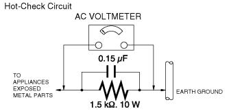
1.3.Leakage Current Hot Check
(See Figure 1.)
1.Plug the AC cord directly into the AC outlet. Do not use an isolation transformer for this check.
2.Connect a 1.5 kΩ, 10 W resistor, in parallel with a 0.15 μF capacitor, between each exposed metallic part on the set and a good earth ground, as shown in Figure 1.
3.Use an AC voltmeter, with 1 kΩ/V or more sensitivity, to measure the potential across the resistor.
4.Check each exposed metallic part, and measure the voltage at each point.
5.Reverse the AC plug in the AC outlet and repeat each of the above measurements.
6.The potential at any point should not exceed 0.75 V RMS. A leakage current tester (Simpson Model 229 or equivalent) may be used to make the hot checks, leakage current must not exceed 1/2 mA. In case a measurement is outside of the limits specified, there is a possibility of a shock hazard, and the equipment should be repaired and rechecked before it is returned to the customer.
Figure. 1
3

2 Warning
2.1.Prevention of Electrostatic Discharge (ESD) to Electrostatically
Sensitive (ES) Devices
Some semiconductor (solid state) devices can be damaged easily by static electricity. Such components commonly are called Electrostatically Sensitive (ES) Devices.
The following techniques should be used to help reduce the incidence of component damage caused by electrostatic discharge (ESD).
1.Immediately before handling any semiconductor component or semiconductor-equipped assembly, drain off any ESD on your body by touching a known earth ground. Alternatively, obtain and wear a commercially available discharging ESD wrist strap, which should be removed for potential shock reasons prior to applying power to the unit under test.
2.After removing an electrical assembly equipped with ES devices, place the assembly on a conductive surface such as aluminum foil, to prevent electrostatic charge buildup or exposure of the assembly.
3.Use only a grounded-tip soldering iron to solder or unsolder ES devices.
4.Use only an antistatic solder removal device. Some solder removal devices not classified as "antistatic (ESD protected)" can generate electrical charge sufficient to damage ES devices.
5.Do not use freon-propelled chemicals. These can generate electrical charges sufficient to damage ES devices.
6.Do not remove a replacement ES device from its protective package until immediately before you are ready to install it. (Most replacement ES devices are packaged with leads electrically shorted together by conductive foam, aluminum foil or comparable conductive material).
7.Immediately before removing the protective material from the leads of a replacement ES device, touch the protective material to the chassis or circuit assembly into which the device will be installed.
CAUTION :
Be sure no power is applied to the chassis or circuit, and observe all other safety precautions.
8.Minimize bodily motions when handling unpackaged replacement ES devices. (Otherwise harmless motion such as the brushing together of your clothes fabric or the lifting of your foot from a carpeted floor can generate static electricity (ESD) sufficient to damage an ES device).
4

2.2.Caution for AC Cord (For EB)
2.2.1.Information for Your Safety
IMPORTANT
Your attention is drawn to the fact that recording of prerecorded tapes or discs or other published or broadcast material may infringe copyright laws.
WARNING
To reduce the risk of fire or shock hazard, do not expose this equipment to rain or moisture.
CAUTION
To reduce the risk of fire or shock hazard and annoying interference, use the recommended accessories only.
FOR YOUR SAFETY
DO NOT REMOVE THE OUTER COVER
To prevent electric shock, do not remove the cover. No user serviceable parts inside. Refer servicing to qualified service personnel.
2.2.2.Caution for AC Mains Lead
For your safety, please read the following text carefully.
This appliance is supplied with a moulded three-pin mains plug for your safety and convenience.
A 5-ampere fuse is fitted in this plug.
Should the fuse need to be replaced please ensure that the replacement fuse has a rating of 5 amperes and it is approved by ASTA or BSI to BS1362
Check for the ASTA mark or the BSI mark on the body of the fuse.
If the plug contains a removable fuse cover you must ensure that it is refitted when the fuse is replaced.
If you lose the fuse cover, the plug must not be used until a replacement cover is obtained.
A replacement fuse cover can be purchased from your local Panasonic Dealer.
If the fitted moulded plug is unsuitable for the socket outlet in your home then the fuse should be removed and the plug cut off and disposed of safety.
There is a danger of severe electrical shock if the cut off plug is inserted into any 13-ampere socket.
If a new plug is to be fitted please observe the wiring code as shown below.
If in any doubt, please consult a qualified electrician.
2.2.2.1.Important
The wires in this mains lead are coloured in accordance with the following code:
Blue |
Neutral |
Brown |
Live |
As the colours of the wires in the mains lead of this appliance may not correspond with the coloured markings identifying the terminals in your plug, proceed as follows:
The wire which is coloured BLUE must be connected to the terminal in the plug which is marked with the letter N or coloured BLACK.
The wire which is coloured BROWN must be connected to the terminal in the plug which is marked with the letter L or coloured RED.
Under no circumstances should either of these wires be connected to the earth terminal of the three pin plug, marked with the letter E or the Earth Symbol.
2.2.2.2.Before Use
Remove the Connector Cover as follows.
2.2.2.3.How to Replace the Fuse
1. Remove the Fuse Cover with a screwdriver.
2. Replace the fuse and attach the Fuse cover.
5
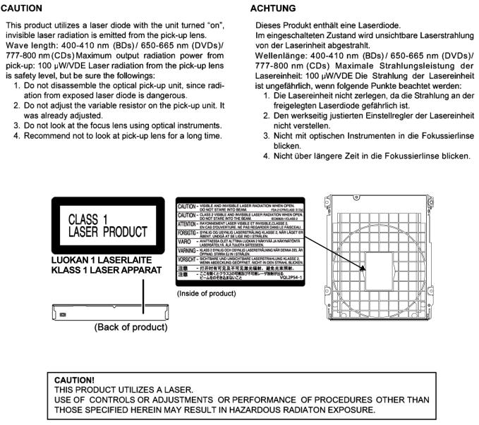
2.3.Precaution of Laser Diode
6

2.4.General Description About Lead Free Solder (PbF)
The lead free solder has been used in the mounting process of all electrical components on the printed circuit boards used for this equipment in considering the globally environmental conservation.
The normal solder is the alloy of tin (Sn) and lead (Pb). On the other hand, the lead free solder is the alloy mainly consists of tin (Sn), silver (Ag) and Copper (Cu), and the melting point of the lead free solder is higher approx.30°C (86°F) more than that of the normal solder.
Distinction of P.C.B. Lead Free Solder being used
Service caution for repair work using Lead Free Solder (PbF)
•The lead free solder has to be used when repairing the equipment for which the lead free solder is used. (Definition: The letter of “PbF” is printed on the P.C.B. using the lead free solder.)
•To put lead free solder, it should be well molten and mixed with the original lead free solder.
•Remove the remaining lead free solder on the P.C.B. cleanly for soldering of the new IC.
•Since the melting point of the lead free solder is higher than that of the normal lead solder, it takes the longer time to melt the lead free solder.
•Use the soldering iron (more than 70W) equipped with the temperature control after setting the temperature at 350±30°C (662±86°F).
Recommended Lead Free Solder (Service Parts Route.)
•The following 3 types of lead free solder are available through the service parts route. SVKZ000001-----------(0.3mm 100g Reel)
SVKZ000002-----------(0.6mm 100g Reel) SVKZ000003-----------(1.0mm 100g Reel)
Note
* Ingredient: Tin (Sn) 96.5%, Silver (Ag) 3.0%, Copper (Cu) 0.5%. (Flux cored)
7
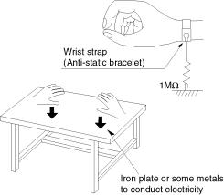
2.5. Static Electricity Protection Measures
• The laser diode in the traverse unit (optical pick-up) may break down due to potential difference caused by static electricity of clothes or human body.
So, be careful of electrostatic breakdown during repair of the traverse unit (optical pick-up).
2.6. Ground for electrostatic breakdown prevention
•As for parts that use optical pick-up (laser diode), the optical pick-up is destroyed by the static electricity of the working environment.
Repair in the working environment that is grounded.
2.6.1. Work table grounding
• Put a conductive material (sheet) or steel sheet on the area where the traverse unit (optical pick-up) is placed, and ground the sheet.
2.6.2. Human body grounding
• Use the anti-static wrist strap to discharge the static electricity from your body.
2.6.3.When exchange the BDP Drive
•Before remove the ESD prevention bag, make sure to use the anti-static wrist strap to discharge the static electricity when replace the BDP Drive.
Note:
The ESD prevention bag is used to replace the original short-circuit point.
It can be removed while placing the BDP Drive.
8
3 Service Navigation
3.1.Service Infomation
This service manual contains technical information which will allow service personnel’s to understand and service this model. Please place orders using the parts list and not the drawing reference numbers.
If the circuit is changed or modified, this information will be followed by service manual to be filed with original service manual.
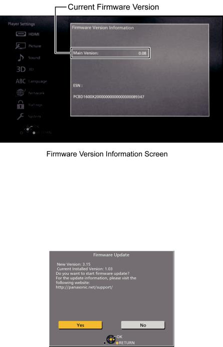
3.2.How to Update Firmware
The firmware of the unit may be renewed to improve the quality including operational performance and playability. Make sure to refer the following procedure when performing version-up.
3.2.1.Confirmation of the Firmware Version
Perform following steps to checking the firmware version currently installed in the unit.
1.Turn the unit on and wait the Home screen is displayed.
2.Select [Setup] → [Player Settings] → [System] → [System Information] → [Firmware Version Information].
3.Firmware Version Information screen is displayed.
3.2.2.Updating Firmware
This unit has 2 updating method, one way to update via the internet, the other way to update using CD-R or USB device which is stored pre-downloaded firmware update file.
3.2.2.1.Updating firmware via the internet
Occasionally, Panasonic may release updated
firmware for this unit that may add or improve the way a feature operates. These updates are available free of charge.
This unit is capable of checking the firmware automatically when connected to the Internet via a broadband connection. When a new firmware version is available, the following message is displayed.
9
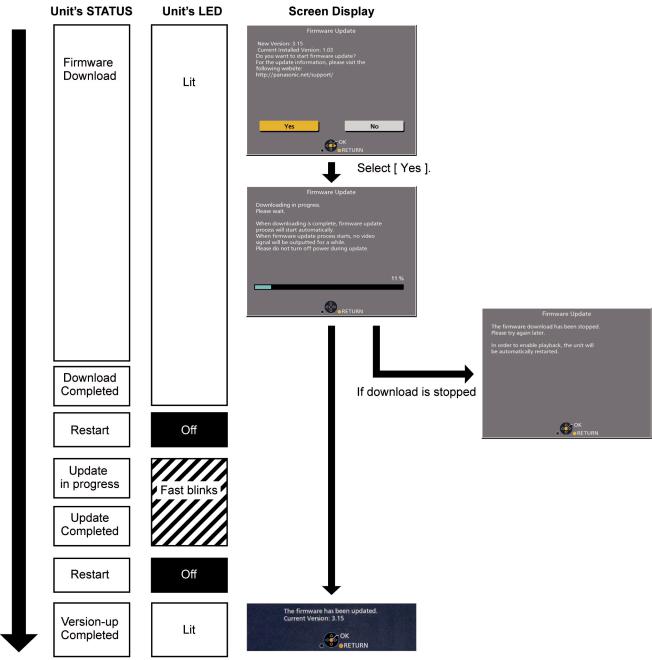
[ Update procedure]
DO NOT DISCONNECT the unit from the AC
power or perform any operation while the update takes place.
10
3.2.2.2.Updating firmware using the USB device
When updating firmware using USB device, perform following procedures. (When using CD-R instead of USB device, perform same procedures)
1.Download the latest firmware file of the unit
The latest firmware required for version-up can be downloaded from TSN-Web site. Click file name to download.
After download, click file to decompress.
2.Decompress the downloaded file
The decompressed file will be named as follows. File Name: PANAEUSB.FRM
Copy the file to root folder of the USB device.
(If using CD-R instead of USB device, burn the file to a blank CD-R by writing software.)
3.Update the unit
Turn the unit on and home screen displayed, the firmware update is completed.
11

4 Specifications
The following specification is for DMP-UB400EB/UB300EB. Some specifications may differ depending on model suffix.
12

13

14
Loading...