


Order No: PAPAMY1312037CE
Air Conditioner
Outdoor Unit
CU-5E36QBU
Destination
U.S.A.
Canada
Please file and use this manual together with the service manual for Model No. CS-E9NKUAW CS-E12NKUAW CS-E18NKUA, CS-E24NKUA, CS-ME7QKUA, Order No. PHAAM1111087C1 PAPAMY1204088CE PAPAMY1312045CE
 WARNING
This service information is designed for experienced repair technicians only and is not designed for use by the general public.
It does not contain warnings or cautions to advise non-technical individuals of potential dangers in attempting to service a product. Products powered by electricity should be serviced or repaired only by experienced professional technicians. Any attempt to service or repair the product or products dealt with in this service information by anyone else could result in serious injury or death.
 PRECAUTION OF LOW TEMPERATURE
In order to avoid frostbite, be assured of no refrigerant leakage during the installation or repairing of refrigerant circuit.
© Panasonic Corporation 2013
TABLE OF CONTENTS
|
|
|
PAGE |
|
|
PAGE |
1. |
Safety Precautions ............................................. |
3 |
15. Troubleshooting Guide.................................... |
31 |
||
2. |
Specifications ..................................................... |
5 |
15.1 |
Self Diagnosis Function.............................. |
31 |
|
3. |
Dimensions ......................................................... |
9 |
16. Disassembly and Assembly Instructions ...... |
34 |
||
4. |
Refrigeration Cycle Diagram........................... |
10 |
16.1 Outdoor Unit Removal Procedure .............. |
34 |
||
5. |
Block Diagram .................................................. |
11 |
17. Technical Data .................................................. |
37 |
||
6. |
Wiring Connection Diagram ............................ |
12 |
17.1 |
Operation Characteristics........................... |
37 |
|
7. |
Electronic Circuit Diagram .............................. |
13 |
18. Exploded View and Replacement Parts |
69 |
||
8. |
Printed Circuit Board |
14 |
List |
..................................................................... |
||
|
|
|
||||
8.1 |
Main Printed Circuit Board ......................... |
14 |
|
|
|
|
8.2 |
Noise Filter Printed Circuit Board ............... |
15 |
|
|
|
|
8.3 |
Display Printed Circuit Board ..................... |
15 |
|
|
|
|
9. |
Installation Information.................................... |
16 |
|
|
|
|
9.1 |
Check Points .............................................. |
16 |
|
|
|
|
10. |
Installation Instruction..................................... |
17 |
|
|
|
|
10.1 |
Select The Best Location ........................... |
17 |
|
|
|
|
10.2 |
Install The Outdoor Unit ............................. |
18 |
|
|
|
|
10.3 |
Connect The Piping.................................... |
18 |
|
|
|
|
10.4 |
Evacuation Of The Equipment ................... |
19 |
|
|
|
|
10.5Connect The Cable To The Outdoor
|
|
Unit ............................................................. |
20 |
10.6 |
Heat Insulation............................................ |
20 |
|
10.7 |
Disposal Of Outdoor Unit Drain Water ....... |
21 |
|
11. |
Operation Control............................................. |
22 |
|
11.1 |
Cooling Operation....................................... |
22 |
|
11.2 |
Heating Operation ...................................... |
23 |
|
12. |
Simultaneous Operation Control.................... |
24 |
|
13. |
Protection Control............................................ |
25 |
|
13.1 |
Freeze Prevention control (Cool) ............... |
25 |
|
13.2 |
Dew Prevention control (Cool) ................... |
25 |
|
13.3Electronic Parts Temperature Rise
Protection 1 (Cool) |
......................................25 |
13.4Electronic Parts Temperature Rise
|
Protection 2 (Cool)...................................... |
25 |
13.5 |
Cooling overload control (Cool).................. |
26 |
13.6 |
Heating overload control (Heat) ................. |
26 |
13.7Extreme Low Temperature Compressor
|
low pressure protection control (Heat) ....... |
26 |
13.8 |
Deice Control.............................................. |
27 |
13.9 |
Time Delay Safety Control |
|
|
(Restart Control) ......................................... |
27 |
13.10 |
30 seconds Force Operation ...................... |
27 |
13.11 |
Total Current Control.................................. |
27 |
13.12 |
IPM (power transistor) Protection |
|
|
Control ........................................................ |
27 |
13.13 |
Compressor Protection Control |
|
|
(Gas leak detection control 1) .................... |
28 |
13.14 |
Compressor Protection Control |
|
|
(Gas leak detection control 2) .................... |
28 |
13.15 |
Valve close detection control...................... |
28 |
13.16 |
Compressor discharge high pressure |
|
|
protection control ........................................ |
28 |
14. Servicing Mode................................................. |
29 |
|
2
1. Safety Precautions
Read the following “SAFETY PRECAUTIONS” carefully before perform any servicing.
Electrical work must be installed or serviced by a licensed electrician. Be sure to use the correct rating of the power plug and main circuit for the model installed.
The caution items stated here must be followed because these important contents are related to safety. The meaning of each indication used is as below. Incorrect installation or servicing due to ignoring of the instruction will cause harm or damage, and the seriousness is classified by the following indications.
WARNING |
This indication shows the possibility of causing death or serious injury. |
CAUTION |
This indication shows the possibility of causing injury or damage to properties. |
The items to be followed are classified by the symbols:
This symbol denotes item that is PROHIBITED from doing.
Carry out test run to confirm that no abnormality occurs after the servicing. Then, explain to user the operation, care and maintenance as stated in instructions. Please remind the customer to keep the operating instructions for future reference.
WARNING
1.Do not modify the machine, part, material during repairing service.
2.If wiring unit is supplied as repairing part, do not repair or connect the wire even only partial wire break. Exchange the whole wiring unit.
3.Do not wrench the fasten terminal. Pull it out or insert it straightly.
4.Engage dealer or specialist for installation and servicing. If installation or servicing done by the user is defective, it will cause water leakage, electrical shock or fire.
5.Install according to this installation instructions strictly. If installation is defective, it will cause water leakage, electric shock or fire.
6.Use the attached accessories parts and specified parts for installation and servicing. Otherwise, it will cause the set to fall, water leakage, fire or electrical shock.
7.Install at a strong and firm location which is able to withstand the set’s weight. If the strength is not enough or installation is not properly done, the set will drop and cause injury.
8.For electrical work, follow the local national wiring standard, regulation and the installation instruction. An independent circuit and single outlet must be used. If electrical circuit capacity is not enough or defect found in electrical work, it will cause electrical shock or fire.
9.This equipment is strongly recommended to install with Earth Leakage Circuit Breaker (ELCB) or Residual Current Device (RCD). Otherwise, it may cause electrical shock and fire in case equipment breakdown or insulation breakdown.
10.Do not use joint cable for indoor/outdoor connection cable. Use the specified indoor/outdoor connection cable, refer to Installation Instruction CONNECT THE CABLE TO THE INDOOR UNIT and connect tightly for indoor/outdoor connection. Clamp the cable so that no external force will be acted on the terminal. If connecting or fixing is not perfect, it will cause heat up or fire at the connection.
11.Wire routing must be properly arranged so that control board cover is fixed properly. If control board cover is not fixed perfectly, it will cause heat-up or fire at the connection point of terminal, fire or electrical shock.
12.When install or relocate air conditioner, do not let any substance other than the specified refrigerant, eg. air etc. mix into refrigeration cycle (piping). (Mixing of air etc. will cause abnormal high pressure in refrigeration cycle and result in explosion, injury etc.).
13.Do not install outdoor unit near handrail of veranda. When installing air-conditioner unit at veranda of high rise building, child may climb up to outdoor unit and cross over the handrail and causing accident.
14.This equipment must be properly earthed. Earth line must not be connected to gas pipe, water pipe, earth of lightning rod and telephone. Otherwise, it may cause electric shock in case equipment breakdown or insulation breakdown.
15.Keep away from small children, the thin film may cling to nose and mouth and prevent breathing.
16.Do not use unspecified cord, modified cord, joint cord or extension cord for power supply cord. Do not share the single outlet with other electrical appliances. Poor contact, poor insulation or over current will cause electrical shock or fire.
17.Tighten the flare nut with torque wrench according to specified method. If the flare nut is over-tightened, after a long period, the
flare may break and cause refrigerant gas leakage.
3
18.For R410A models, when connecting the piping, do not use any existing (R22) pipes and flare nuts. Using such same may cause abnormally high pressure in the refrigeration cycle (piping), and possibly result in explosion and injury. Use only R410A materials.
Thickness of copper pipes used with R410A must be more than 1/32" (0.8mm). Never use copper pipes thinner than 1/32" (0.8mm). It is desirable that the amount of residual oil is less than 0.0014 oz/32.8 ft (40 mg/10m).
19.During installation, install the refrigerant piping properly before run the compressor. (Operation of compressor without fixing refrigeration piping and valves at opened condition will cause suck-in of air, abnormal high pressure in refrigeration cycle and result in explosion, injury etc.).
20.During pump down operation, stop the compressor before remove the refrigeration piping. (Removal of refrigeration piping while compressor is operating and valves are opened condition will cause suck-in of air, abnormal high pressure in refrigeration cycle and result in explosion, injury etc.).
21.After completion of installation or service, confirm there is no leakage or refrigerant gas. It may generate toxic gas when the refrigerant contacts with fire.
22.Ventilate if there is refrigerant gas leakage during operation. It may cause toxic gas when refrigerant contacts with fire.
23.Do not insert your fingers or other objects into the unit, high speed rotating fan may cause injury.
24.Must not use other parts except original parts described in catalog and manual.
25.Using of refrigerant other than the specified type may cause product damage, burst and injury etc.
CAUTION
1.Do not install the unit at place where leakage of flammable gas may occur. In case gas leaks and accumulates at surrounding of the unit, it may cause fire.
2.Carry out drainage piping as mentioned in installation instructions. If drainage is not perfect, water may enter the room and damage the furniture.
3.Tighten the flare nut with torque wrench according to specified method. If the flare nut is over-tightened, after a long period, the flare may break and cause refrigerant gas leakage.
4. Do not touch outdoor unit air inlet and aluminium fin. It may cause injury.
5.Select an installation location which is easy for maintenance.
6.Pb free solder has a higher melting point than standard solder; typically the melting point is 50°F – 70°F (30°C – 40°C) higher. Please use
a high temperature solder iron. In case of the soldering iron with temperature control, please set it to 700 ± 20°F (370 ± 10°C). Pb free solder will tend to splash when heated too high (about 1100°F / 600°C).
7.Power supply connection to the room air conditioner.
Power supply cord shall be UL listed or CSA approved 3 conductor with minimum AWG12 wires.
Power supply point should be in an easily accessible place for power disconnection in case of emergency. In some countries, permanent connection of this air conditioner to the power supply is prohibited.
Fix power supply connection to a circuit breaker for permanent connection.
Use NRTL approved fuse or circuit breaker (rating refers to name plate) for permanent connection.
8.Do not release refrigerant during piping work for installation, servicing, reinstallation and during repairing a refrigerant parts. Take care of the liquid refrigerant, it may cause frostbite.
9.Installation or servicing work: It may need two people to carry out the installation or servicing work.
10.Do not install this appliance in a laundry room or other location where water may drip from the ceiling, etc.
11.Do not sit or step on the unit, you may fall down accidentally.
12.Do not touch the sharp aluminum fins or edges of metal parts.
If you are required to handle sharp parts during installation or servicing, please wear hand glove. Sharp parts may cause injury.
4
2. Specifications
|
Item |
|
Unit |
OUTDOOR UNIT |
|
|
|
|
|
|
|
Indoor Unit Combination |
|
|
|
|
2.0kW + 2.0kW + 2.0kW + 2.0kW + 2.5kW |
|
|
|
|
|
|
Power Source |
|
|
|
|
1 Phase, 208-230V, 60Hz (Power supply from outdoor unit) |
|
|
|
|
|
|
|
Capacity |
|
kW |
10.56 (2.9 ~ 11.5) |
|
|
|
|
|
||
|
|
BTU/h |
36000 (9900 ~ 39000) |
||
|
|
|
|
||
|
|
|
|
|
|
|
Electrical |
|
Running Current |
A |
19.0 - 17.2 |
|
|
|
|
|
|
Cooling Operation |
|
Power Input |
kW |
3.75 (0.55 ~ 3.86) |
|
Data |
|
||||
|
|
|
|
|
|
|
|
|
EER |
W/W |
2.82 (5.27 ~ 2.98) |
|
|
|
|
|
|
|
Noise |
|
Sound Pressure Level |
dB-A (H/L) |
55 / - |
|
|
|
|
|
|
|
|
Sound Power Level |
dB (H/L) |
71 / - |
|
|
|
|
|||
|
|
|
|
|
|
|
Capacity |
|
kW |
11.1 (3.4 ~ 14.5) |
|
|
|
|
|
||
|
|
BTU/h |
37800 (11600 ~ 49500) |
||
|
|
|
|
||
|
|
|
|
|
|
|
Electrical |
|
Running Current |
A |
14.8 - 13.4 |
|
|
|
|
|
|
Heating Operation |
|
Power Input |
kW |
2.90 (0.53 ~ 4.24) |
|
Data |
|
||||
|
|
|
|
|
|
|
|
|
COP |
W/W |
3.82 (6.42 ~ 3.42) |
|
|
|
|
|
|
|
Noise |
|
Sound Pressure Level |
dB-A (H/L) |
55 / - |
|
|
|
|
|
|
|
|
Sound Power Level |
dB (H/L) |
71 / - |
|
|
|
|
|||
|
|
|
|
|
|
Maximum Current |
|
|
|
A |
21.3 |
|
|
|
|
|
|
Starting Current |
|
|
|
A |
19.0 |
|
|
|
|
|
|
Circuit Breaker Capacity |
|
|
|
A |
30 |
|
|
|
|
|
|
|
Height |
|
mm (inch) |
999 (39-11/32) |
|
|
|
|
|
|
|
Dimension |
Width |
|
mm (inch) |
940 (37-1/32) |
|
|
|
|
|
|
|
|
Depth |
|
mm (inch) |
340 (13-13/32) |
|
|
|
|
|
|
|
Net Weight |
|
|
|
kg (lb) |
83 (183) |
|
|
|
|
|
|
Connection Cable |
|
|
|
|
3 + 1 (Earth) min AWG16 |
|
|
|
|
|
|
Pipe Length Range (1 room) |
|
|
|
m (ft) |
3 ~ 25 (9.8 ~ 82.0) |
|
|
|
|
||
Maximum Pipe Length (Total Room) |
|
m (ft) |
80 (262.4) |
||
|
|
|
|
|
|
Refrigerant Pipe Diameter |
Liquid Side |
|
mm (inch) |
6.35 (1/4) |
|
|
|
|
|
|
|
Gas Side |
|
mm (inch) |
9.52 (3/8), (E24: 12.70 (1/2)) |
||
|
|
||||
|
|
|
|
|
|
|
Type |
|
|
Hermetic Motor / Rotary |
|
|
|
|
|
|
|
Compressor |
Motor Type |
|
|
Brushless (4-poles) |
|
|
|
|
|
|
|
|
Rated Output |
|
W |
1.30k |
|
|
|
|
|
|
|
|
Type |
|
|
Propeller Fan |
|
|
|
|
|
|
|
Air Circulation |
Motor Type |
|
|
DC Motor (8-poles) |
|
|
|
|
|
|
|
|
Rated Output |
|
W |
90 |
|
|
|
|
|
||
Fan Speed |
High (Cooling / Heating) |
RPM |
750 / 740 |
||
|
|
|
|
|
|
|
Type |
|
|
Plate fin configuration forced draft type |
|
|
|
|
|
||
|
Tube Material |
|
Copper |
||
|
|
|
|
|
|
Heat Exchanger |
Fin Material |
|
|
Aluminum (Blue Coated) |
|
|
|
|
|
|
|
|
Row / Stage |
|
|
2 / 46 |
|
|
|
|
|
|
|
|
FPI |
|
|
19 |
|
|
|
|
|
|
|
Air Volume |
High (Cooling / Heating) |
m3/min |
71.2 (2512) / 70.1 (2475) |
||
(ft3/min) |
|||||
Refrigerant Control Device |
|
|
|
|
Expansion Valve |
|
|
|
|
|
|
Refrigerant Oil |
|
|
|
|
FV50S |
|
|
|
|
|
|
Refrigerant (R410A) |
|
|
|
g (oz) |
3.40k (120) |
|
|
|
|
|
|
5

|
Item |
Unit |
|
|
OUTDOOR UNIT |
||
|
|
|
|
|
|
|
|
|
|
|
|
|
Dry Bulb |
|
Wet Bulb |
|
|
|
|
|
|
|
|
|
Cooling |
Maximum |
°C (°F) |
32 (89.6) |
|
23 (73.4) |
|
|
|
|
|
|
|
|
|
Indoor Operation Range |
Minimum |
°C (°F) |
16 (60.8) |
|
11 (51.8) |
||
|
|
||||||
|
|
|
|
|
|
|
|
Heating |
Maximum |
°C (°F) |
30 (86.0) |
|
— |
||
|
|
||||||
|
|
|
|
|
|
|
|
|
Minimum |
°C (°F) |
16 (60.8) |
|
— |
||
|
|
|
|||||
|
|
|
|
|
|
|
|
|
Cooling |
Maximum |
°C (°F) |
46 (114.8) |
|
26 (78.8) |
|
|
|
|
|
|
|
|
|
Outdoor Operation Range |
Minimum |
°C (°F) |
-10 (14.0) |
|
— |
||
|
|
||||||
|
|
|
|
|
|
|
|
Heating |
Maximum |
°C (°F) |
24 (75.2) |
|
18 (64.4) |
||
|
|
||||||
|
|
|
|
|
|
|
|
|
Minimum |
°C (°F) |
-15 (5.0) |
|
-16 (3.2) |
||
|
|
|
|||||
|
|
|
|
|
|
|
|
Note
Specifications are subject to change without notice for further improvement.
6
Multi Split Combination Possibility:
o A single outdoor unit enables air conditioning of up to five separate rooms.
7
Indoor Unit : CS-ME7QKUA, CS-E9NKUAW, CS-E12NKUAW, CS-E18NKUA, CS-E24NKUA
Outdoor Unit : CU-5E36QBU
5 Room |
|
4 Room |
|
3 Room |
2 Room |
1 Room |
||||
Indoor Unit Capacity |
Total Indoor |
Indoor Unit |
Total Indoor |
Indoor Unit |
Total Indoor |
Indoor Unit |
Total Indoor |
Indoor Unit |
Total Indoor |
|
(kW) |
Capacity |
Capacity (kW) |
|
Capacity |
Capacity |
Capacity |
Capacity |
Capacity |
Capacity |
Capacity |
(kW) |
|
(kW) |
(kW) |
(kW) |
(kW) |
(kW) |
(kW) |
(kW) |
||
|
|
|
||||||||
2.0+2.0+2.0+2.0+2.0 |
10.0 |
2.0+2.0+2.0+2.0 |
|
8.0 |
2.0+2.0+2.0 |
6.0 |
2.0+2.5 |
4.5 |
2.0 |
2.0 |
2.0+2.0+2.0+2.0+2.5 |
10.5 |
2.0+2.0+2.0+2.5 |
|
8.5 |
2.0+2.0+2.5 |
6.5 |
2.0+3.2 |
5.2 |
2.5 |
2.5 |
2.0+2.0+2.0+2.0+3.2 |
11.2 |
2.0+2.0+2.0+3.2 |
|
9.2 |
2.0+2.0+3.2 |
7.2 |
2.0+5.0 |
7.0 |
3.2 |
3.2 |
2.0+2.0+2.0+2.0+5.0 |
13.0 |
2.0+2.0+2.0+5.0 |
|
11.0 |
2.0+2.0+5.0 |
9.0 |
2.0+7.0 |
9.0 |
5.0 |
5.0 |
2.0+2.0+2.0+2.0+7.0 |
15.0 |
2.0+2.0+2.0+7.0 |
|
13.0 |
2.0+2.0+7.0 |
11.0 |
2.5+2.5 |
5.0 |
7.0 |
7.0 |
2.0+2.0+2.0+2.5+2.5 |
11.0 |
2.0+2.0+2.5+2.5 |
|
9.0 |
2.0+2.5+2.5 |
7.0 |
2.5+3.2 |
5.7 |
|
|
2.0+2.0+2.0+2.5+3.2 |
11.7 |
2.0+2.0+2.5+3.2 |
|
9.7 |
2.0+2.5+3.2 |
7.7 |
2.5+5.0 |
7.5 |
|
|
2.0+2.0+2.0+2.5+5.0 |
13.5 |
2.0+2.0+2.5+5.0 |
|
11.5 |
2.0+2.5+5.0 |
9.5 |
2.5+7.0 |
9.5 |
|
|
2.0+2.0+2.0+2.5+7.0 |
15.5 |
2.0+2.0+2.5+7.0 |
|
13.5 |
2.0+2.5+7.0 |
11.5 |
3.2+3.2 |
6.4 |
|
|
2.0+2.0+2.0+3.2+3.2 |
12.4 |
2.0+2.0+3.2+3.2 |
|
10.4 |
2.0+3.2+3.2 |
8.4 |
3.2+5.0 |
8.2 |
|
|
2.0+2.0+2.0+3.2+5.0 |
14.2 |
2.0+2.0+3.2+5.0 |
|
12.2 |
2.0+3.2+5.0 |
10.2 |
3.2+7.0 |
10.2 |
|
|
2.0+2.0+2.0+3.2+7.0 |
16.2 |
2.0+2.0+3.2+7.0 |
|
14.2 |
2.0+3.2+7.0 |
12.2 |
5.0+5.0 |
10.0 |
|
|
2.0+2.0+2.0+5.0+5.0 |
16.0 |
2.0+2.0+5.0+5.0 |
|
14.0 |
2.0+5.0+5.0 |
12.0 |
5.0+7.0 |
12.0 |
|
|
2.0+2.0+2.5+2.5+2.5 |
11.5 |
2.0+2.0+5.0+7.0 |
|
16.0 |
2.0+5.0+7.0 |
14.0 |
7.0+7.0 |
14.0 |
|
|
2.0+2.0+2.5+2.5+3.2 |
12.2 |
2.0+2.5+2.5+2.5 |
|
9.5 |
2.0+7.0+7.0 |
16.0 |
|
|
|
|
2.0+2.0+2.5+2.5+5.0 |
14.0 |
2.0+2.5+2.5+3.2 |
|
10.2 |
2.5+2.5+2.5 |
7.5 |
|
|
|
|
2.0+2.0+2.5+2.5+7.0 |
16.0 |
2.0+2.5+2.5+5.0 |
|
12.0 |
2.5+2.5+3.2 |
8.2 |
|
|
|
|
2.0+2.0+2.5+3.2+3.2 |
12.9 |
2.0+2.5+2.5+7.0 |
|
14.0 |
2.5+2.5+5.0 |
10.0 |
|
|
|
|
2.0+2.0+2.5+3.2+5.0 |
14.7 |
2.0+2.5+3.2+3.2 |
|
10.9 |
2.5+2.5+7.0 |
12.0 |
|
|
|
|
2.0+2.0+2.5+3.2+7.0 |
16.7 |
2.0+2.5+3.2+5.0 |
|
12.7 |
2.5+3.2+3.2 |
8.9 |
|
|
|
|
2.0+2.0+2.5+5.0+5.0 |
16.5 |
2.0+2.5+3.2+7.0 |
|
14.7 |
2.5+3.2+5.0 |
10.7 |
|
|
|
|
2.0+2.0+3.2+3.2+3.2 |
13.6 |
2.0+2.5+5.0+5.0 |
|
14.5 |
2.5+3.2+7.0 |
12.7 |
|
|
|
|
2.0+2.0+3.2+3.2+5.0 |
15.4 |
2.0+2.5+5.0+7.0 |
|
16.5 |
2.5+5.0+5.0 |
12.5 |
|
|
|
|
2.0+2.0+3.2+3.2+7.0 |
17.4 |
2.0+3.2+3.2+3.2 |
|
11.6 |
2.5+5.0+7.0 |
14.5 |
|
|
|
|
2.0+2.0+3.2+5.0+5.0 |
17.2 |
2.0+3.2+3.2+5.0 |
|
13.4 |
2.5+7.0+7.0 |
16.5 |
|
|
|
|
2.0+2.5+2.5+2.5+2.5 |
12.0 |
2.0+3.2+3.2+7.0 |
|
15.4 |
3.2+3.2+3.2 |
9.6 |
|
|
|
|
2.0+2.5+2.5+2.5+3.2 |
12.7 |
2.0+3.2+5.0+5.0 |
|
15.2 |
3.2+3.2+5.0 |
11.4 |
|
|
|
|
2.0+2.5+2.5+2.5+5.0 |
14.5 |
2.0+3.2+5.0+7.0 |
|
17.2 |
3.2+3.2+7.0 |
13.4 |
|
|
|
|
2.0+2.5+2.5+2.5+7.0 |
16.5 |
2.0+5.0+5.0+5.0 |
|
17.0 |
3.2+5.0+5.0 |
13.2 |
|
|
|
|
2.0+2.5+2.5+3.2+3.2 |
13.4 |
2.5+2.5+2.5+2.5 |
|
10.0 |
3.2+5.0+7.0 |
15.2 |
|
|
|
|
2.0+2.5+2.5+3.2+5.0 |
15.2 |
2.5+2.5+2.5+3.2 |
|
10.7 |
3.2+7.0+7.0 |
17.2 |
|
|
|
|
2.0+2.5+2.5+3.2+7.0 |
17.2 |
2.5+2.5+2.5+5.0 |
|
12.5 |
5.0+5.0+5.0 |
15.0 |
|
|
|
|
2.0+2.5+2.5+5.0+5.0 |
17.0 |
2.5+2.5+2.5+7.0 |
|
14.5 |
5.0+5.0+7.0 |
17.0 |
|
|
|
|
2.0+2.5+3.2+3.2+3.2 |
14.1 |
2.5+2.5+3.2+3.2 |
|
11.4 |
|
|
|
|
|
|
2.0+2.5+3.2+3.2+5.0 |
15.9 |
2.5+2.5+3.2+5.0 |
|
13.2 |
|
|
|
|
|
|
2.0+3.2+3.2+3.2+3.2 |
14.8 |
2.5+2.5+3.2+7.0 |
|
15.2 |
|
|
|
|
|
|
2.0+3.2+3.2+3.2+5.0 |
16.6 |
2.5+2.5+5.0+5.0 |
|
15.0 |
|
|
|
|
|
|
2.5+2.5+2.5+2.5+2.5 |
12.5 |
2.5+2.5+5.0+7.0 |
|
17.0 |
|
|
|
|
|
|
2.5+2.5+2.5+2.5+3.2 |
13.2 |
2.5+3.2+3.2+3.2 |
|
12.1 |
|
|
|
|
|
|
2.5+2.5+2.5+2.5+5.0 |
15.0 |
2.5+3.2+3.2+5.0 |
|
13.9 |
|
|
|
|
|
|
2.5+2.5+2.5+2.5+7.0 |
17.0 |
2.5+3.2+3.2+7.0 |
|
15.9 |
|
|
|
|
|
|
2.5+2.5+2.5+3.2+3.2 |
13.9 |
2.5+3.2+5.0+5.0 |
|
15.7 |
|
|
|
|
|
|
2.5+2.5+2.5+3.2+5.0 |
15.7 |
2.5+5.0+5.0+5.0 |
|
17.5 |
|
|
|
|
|
|
2.5+2.5+2.5+5.0+5.0 |
17.5 |
3.2+3.2+3.2+3.2 |
|
12.8 |
|
|
|
|
|
|
2.5+2.5+3.2+3.2+3.2 |
14.6 |
3.2+3.2+3.2+5.0 |
|
14.6 |
|
|
|
|
|
|
2.5+2.5+3.2+3.2+5.0 |
16.4 |
3.2+3.2+3.2+7.0 |
|
16.6 |
|
|
|
|
|
|
2.5+3.2+3.2+3.2+3.2 |
15.3 |
3.2+3.2+5.0+5.0 |
|
16.4 |
|
|
|
|
|
|
2.5+3.2+3.2+3.2+5.0 |
17.1 |
|
|
|
|
|
|
|
|
|
3.2+3.2+3.2+3.2+3.2 |
16.0 |
|
|
|
|
|
|
|
|
|
8
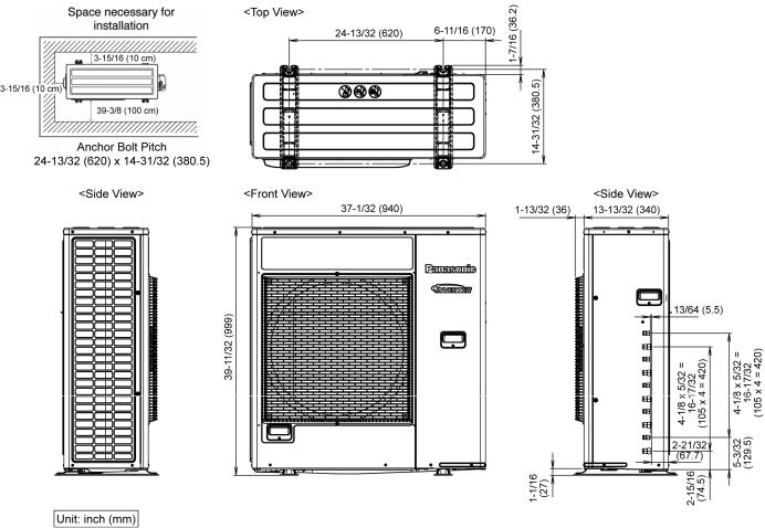
3. Dimensions
9
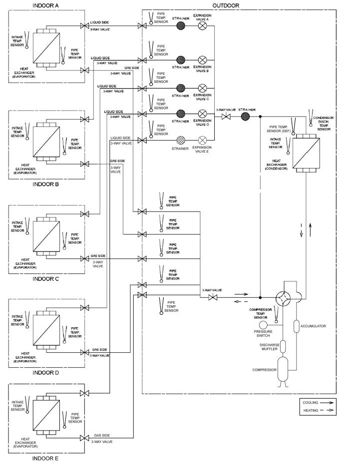
4. Refrigeration Cycle Diagram
10
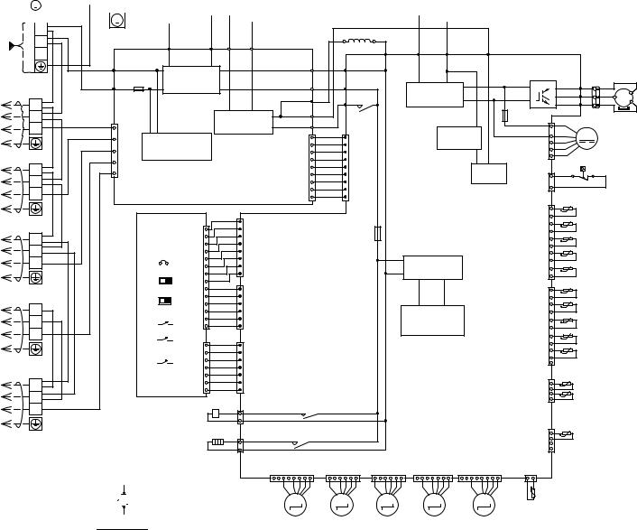
5. Block Diagram
11
12
Resistance of Compressor Windings
|
|
|
|
|
|
|
|
|
|
|
|
|
|
|
|
|
CONNECTION |
5KD240XAL21 (Ω) |
|
|
|||
|
|
|
|
|
|
|
|
|
|
|
|
|
|
|
|
|
|
|
|
|
|
|
|
|
|
|
|
|
|
|
|
|
|
|
|
|
|
|
|
|
U - V |
0.72 |
|
|
|||
|
|
|
|
|
|
|
|
|
|
|
|
|
|
|
|
|
|
|
|
|
|
|
|
|
|
|
|
|
|
|
|
|
|
|
|
|
|
|
|
|
U - W |
0.73 |
|
|
|||
|
|
|
|
|
|
|
|
|
|
|
|
|
|
|
|
|
|
|
|
|
|
|
|
CONTROL BOARD |
|
V - W |
0.71 |
|
|
||||||||||||||||||
|
|
|
|
|
|
|
|
Y/G |
|
|
|
|
|
|
|
|
|||||||
|
|
|
|
|
|
|
|
|
|
|
|
|
|
|
|
|
G |
|
|
|
|||
|
|
|
|
|
|
|
|
|
|
|
|
|
|
|
|
|
|
|
|||||
|
|
|
|
|
|
|
|
|
|
|
|
|
|
|
|
G |
|
|
|
|
|
|
|
|
|
|
|
|
|
|
|
BL |
|
|
|
|
|
||||||||||
|
|
|
|
|
|
|
|
|
|
|
|
|
|
|
|
|
|||||||
POWER SUPPLY |
L1 |
|
CONTROL BOARD |
|
|
|
|
|
|
|
|
REACTOR |
|
|
|
|
|
|
|
|
|
|
|
|
|
|||
W |
|
|
|
|
|
|
|
|
|
GRY |
|
|
|
|
|
|
|
|
|
|
|
|
||||||
SINGLE PHASE |
|
|
|
|
|
|
|
|
|
|
|
|
|
R |
BL |
|
|
|
|
|
|
|
|
|
|
|||
AC 208/230V |
L2 |
|
|
|
|
|
|
|
|
|
|
|
|
|
|
|
|
|
|
|
|
|
|
|
|
|
||
60Hz |
|
|
|
ACN1 |
FG1 |
|
FG2 |
DCP |
DCN |
CN-WHT |
|
|
AC-WHT |
RAT1 |
DCP |
DCN |
AC1 |
|
|
|
|
|
|
|
|
|
||
|
|
|
|
(GREEN) |
(GREEN) |
(RED) |
(BLACK) |
W |
|
|
|
|
|
|
|
|
|
|
||||||||||
|
|
|
|
(WHITE) |
|
|
|
|
|
|
(WHITE) |
|
(WHITE) |
(GRAY) |
(RED) |
(BLACK) |
(BROWN) |
|
|
|
|
|
|
|
|
|||
TERMINAL BOARD |
|
|
ACL1 |
|
NOISE FILTER |
|
|
|
|
|
AC-BLK |
|
|
|
|
|
Q10 |
|
|
|
|
|
COMPRESSOR |
|||||
|
BL W |
|
|
(BLACK) |
|
CIRCUIT |
|
|
CN-BLK (BLACK) |
BL |
|
(BLACK) |
|
SMOOTHING |
|
|
P |
|
U (RED) U |
R |
R |
|
||||||
TERMINAL BOARD |
|
|
FUSE 401 |
|
|
|
|
RAT2 (GRAY) |
GRY |
|
|
|
|
|
|
|
V |
(BLUE) V |
B |
B |
MS |
|||||||
A |
|
|
|
|
|
|
|
|
RY-PWR |
|
CAPACITOR |
|
|
N |
|
|
W |
Y |
Y |
|||||||||
UNIT |
1 |
|
|
(30A 250V) |
|
|
|
|
|
AC1 |
|
|
|
|
|
|
W |
|
3~ |
|||||||||
|
|
|
|
|
|
|
|
|
|
BR |
|
AC2 |
|
|
|
|
(T3.15A |
|
|
|
(YELLOW) |
|
|
|||||
|
|
|
|
|
|
|
|
|
|
|
(BROWN) |
|
|
|
|
|
|
|
|
|
|
|||||||
|
|
|
|
|
|
|
|
|
|
|
|
|
|
|
|
|
|
|
|
FUSE 1 |
|
|
|
|
|
|||
BUNITTO INDOOR |
2 |
|
|
|
|
|
|
|
RECTIFICATION |
AC2 (BLUE) |
|
|
(BLUE) |
|
|
|
|
L250V) |
|
1 |
|
R |
|
CONNECTOR |
||||
2 |
|
R |
1 |
COM-CN (WHITE) |
|
|
|
B |
W |
|
|
|
CIRCUIT |
|
|
|
WHITE |
|
||||||||||
|
|
|
ELECTRONIC CONTROLLER |
DATA-CN ( |
|
DATA-CN WHITE |
|
|
|
CN-PSW1 |
|
|
|
|
|
|
||||||||||||
|
3 |
|
B |
|
|
|
|
CIRCUIT |
|
1 |
|
W |
1 |
|
|
PFC |
|
|
|
|
|
B |
|
M |
|
|
||
|
|
|
|
3 |
|
COMMUNICATION |
|
|
|
|
|
W |
|
|
CAPACITOR |
CN-FM1 |
4 |
|
BR |
|
|
|
|
|||||
|
BL W |
|
Y |
5 |
|
CIRCUIT |
|
|
|
|
|
|
W |
|
|
|
|
|
(WHITE) |
7 |
|
ORG |
FAN MOTOR |
|
||||
|
|
ORG |
|
|
|
|
|
|
|
) |
|
W |
|
|
|
|
|
|
|
|
|
|
||||||
|
1 |
|
9 |
|
|
|
|
|
|
|
WHITE |
|
W |
) |
|
|
|
PFC |
|
|
1 |
|
R |
|
|
|
|
|
|
|
BR |
|
|
|
|
|
|
|
|
|
|
|
|
|
|
|
|
|
|
||||||||
|
|
|
|
7 |
|
|
|
|
|
|
|
|
|
W |
|
|
|
|
|
|
|
|
|
|
|
|
|
|
INDOOR |
3 |
|
|
|
|
|
(NOISE FILTER) |
|
|
|
|
W |
( |
|
|
|
|
(BLUE) |
2 |
|
R HIGH PRESSURE SW. |
|||||||
|
|
|
|
|
|
|
|
|
|
|
|
W |
|
|
|
|
|
|
|
|||||||||
|
|
|
|
|
|
|
|
|
|
|
9 |
|
9 |
|
|
|
|
|
|
|
||||||||
|
|
|
|
|
|
|
|
|
|
|
|
|
|
|
|
|
|
|
|
1 |
|
|
|
|
|
|
||
TO |
|
|
|
|
|
|
|
|
|
|
|
|
|
|
|
|
|
|
|
|
|
|
t |
|
LIQUID PIPE TEMP. SENSOR |
|||
|
|
|
|
|
|
|
|
|
|
|
|
|
|
|
|
|
|
|
|
|
|
|
|
|||||
BL W |
|
|
|
|
ELECTRONIC |
|
|
1 |
|
|
|
|
L250V) |
|
|
|
|
|
|
|
|
|
(UNIT A) (THERMISTOR) |
|||||
|
|
|
|
1 |
W |
|
|
|
|
|
|
|
|
|
|
|
|
t |
|
|||||||||
|
|
|
|
|
|
|
|
|
|
|
|
|
|
|
|
|
LIQUID PIPE TEMP. SENSOR |
|||||||||||
|
|
|
|
|
|
W |
|
|
|
|
|
|
|
|
|
|
|
|
|
|
|
|
|
|
||||
INDOORUNIT C |
|
|
|
|
|
CONTROLLER |
|
W |
-CNDISP1 |
|
|
|
|
FUSE 2 (T3.15A |
|
|
|
|
CN-TH3 |
|
|
|
|
(UNIT B) (THERMISTOR) |
||||
1 |
|
|
|
|
POWER |
SAVE CN-DISP1 |
(WHITE) |
(WHITE) |
|
|
|
|
CIRCUIT |
|
|
(WHITE) |
|
t |
|
LIQUID PIPE TEMP. SENSOR |
||||||||
|
|
|
|
W |
|
|
|
|
|
|
|
|
||||||||||||||||
|
|
|
|
|
(DISPLAY) |
|
W |
|
|
|
|
|
|
|
|
|
|
|
t |
|
||||||||
|
2 |
|
|
|
|
JP1 |
|
W |
|
|
|
|
|
|
|
|
|
|
|
|
|
|
|
|
(UNIT C) (THERMISTOR) |
|||
|
|
|
|
|
|
COOL ONLY |
|
W |
|
|
|
|
|
|
|
|
|
|
|
|
|
|
t |
|
LIQUID PIPE TEMP. SENSOR |
|||
|
3 |
|
|
|
|
|
|
|
|
|
|
|
RECTIFICATION |
|
|
|
|
|
|
(UNIT D) (THERMISTOR) |
||||||||
|
|
|
|
|
|
|
|
W |
|
|
|
|
|
|
|
|
|
|
|
|
|
|||||||
|
|
|
|
|
|
|
|
|
|
|
|
|
|
|
|
|
|
|
|
|
LIQUID PIPE TEMP. SENSOR |
|||||||
|
|
|
|
|
|
|
|
|
|
|
|
|
|
|
|
|
|
|
|
|
|
|
|
|
|
|||
TO |
|
|
|
|
|
|
|
|
|
8 |
|
|
|
|
|
|
|
|
|
|
10 |
|
|
|
(UNIT E) (THERMISTOR) |
|||
BL |
W |
|
|
|
|
|
|
W |
1 |
|
|
|
|
|
|
|
|
|
|
|
1 |
|
|
|
GAS PIPE TEMP. SENSOR |
|||
|
|
|
|
PRIORITY MODE |
|
|
|
|
|
|
|
|
|
|
|
|
|
|
|
|||||||||
UNITD |
|
|
|
|
W |
DISP2-CN (WHITE) |
|
|
|
|
|
|
|
|
CN-TH4 |
|
|
t |
|
|||||||||
|
|
|
|
|
PUMP DOWN |
|
|
|
|
|
|
|
|
|
|
|
|
|
|
GAS PIPE TEMP. SENSOR |
||||||||
|
|
|
|
|
|
|
|
|
W |
|
|
|
|
|
|
|
|
|
|
|
|
|
|
|
|
(UNIT A) (THERMISTOR) |
||
|
1 |
|
|
|
|
|
|
|
W |
|
|
|
|
|
|
|
SWITCHING |
|
|
|
|
|
t |
|
GAS PIPE TEMP. SENSOR |
|||
|
|
|
|
|
|
|
|
|
|
|
|
|
|
|
|
|
|
|
|
|
(UNIT B) (THERMISTOR) |
|||||||
|
|
|
|
|
|
|
|
W |
|
|
|
|
|
|
|
|
|
|
|
|
|
|
||||||
|
2 |
|
|
|
|
|
|
|
|
|
|
|
|
|
POWER SUPPLY |
|
|
|
|
|
|
|
|
|
|
|||
|
|
|
|
|
|
|
|
W |
|
|
|
|
|
|
|
(WHITE) |
|
t |
|
(UNIT C) (THERMISTOR) |
||||||||
INDOOR |
3 |
|
|
|
|
OPERATION TEST |
14 |
|
6 |
|
|
|
|
|
|
CIRCUIT |
|
|
|
|
|
|
|
|
||||
|
|
|
|
W |
|
|
|
|
|
|
|
|
|
|
|
|
t |
|
GAS PIPE TEMP. SENSOR |
|||||||||
|
|
|
|
|
|
|
|
1 |
1 |
|
|
|
|
|
|
|
|
|
|
|
|
|
|
(UNIT D) (THERMISTOR) |
||||
|
|
|
|
|
|
|
|
|
|
|
|
|
|
|
|
|
|
|
|
|
|
|
||||||
EUNIT TO |
|
|
|
|
|
WIRING CHECK |
|
W |
|
(YELLOW) |
|
|
|
|
|
ELECTRONIC CONTROLLER |
|
|
|
t |
|
GAS PIPE TEMP. SENSOR |
||||||
2 |
|
|
|
|
7 |
|
7 |
|
|
|
|
|
|
|
|
|
||||||||||||
|
|
|
|
|
NMODE1-CN |
W |
|
|
|
|
|
|
|
|
CN-TH1 |
|
t |
|
(UNIT E) (THERMISTOR) |
|||||||||
|
BL W |
|
|
|
|
|
|
(WHITE) |
W |
NMODE - CN |
|
|
|
|
|
|
(MAIN) |
|
|
|
|
1 |
|
SENSOR (THERMISTOR) |
|
|||
|
|
|
|
|
|
|
|
W |
|
|
|
|
|
|
|
|
|
|
|
11 |
|
OUTDOOR TEMP. |
|
|
||||
|
|
|
|
|
|
|
|
|
W |
|
|
|
|
|
|
|
|
|
|
|
|
|
|
|
|
|||
|
1 |
|
|
|
|
|
|
|
W |
|
|
|
|
|
|
|
|
|
|
(WHITE) |
|
t |
|
|
|
|
||
INDOOR |
|
|
|
|
|
|
|
|
|
CN-HOT |
|
|
|
|
|
|
|
|
|
|
4 |
|
DEFROST TEMP. |
|
|
|||
|
3 |
|
|
|
|
|
|
|
|
1 (BLUE) |
RY-HOT |
|
|
|
|
|
|
|
|
|
HEAT EXCHANGER TEMP. |
|
||||||
|
|
|
|
|
|
|
|
|
|
|
|
|
|
|
|
|
|
|
SENSOR (THERMISTOR) |
|
||||||||
|
|
|
|
|
|
|
|
|
|
|
|
|
|
|
|
|
|
|
|
|
|
|
|
|
||||
TO |
|
|
|
|
|
|
ELECTRO MAGNETIC |
3 |
|
|
|
|
|
|
|
|
|
|
|
1 |
|
SENSOR (THERMISTOR) |
|
|||||
|
|
|
|
|
|
|
COIL (4-WAY VALVE) |
1 |
|
RY-HT |
|
|
|
|
|
|
|
(YELLOW) |
|
t |
|
|
|
|
||||
|
|
|
|
|
|
|
|
|
|
|
|
|
|
|
|
|
|
|
|
CN-TH2 |
|
|
|
|
|
|
|
|
REMARKS
B : BLUE BL : BLACK W : WHITE R : RED
Y : YELLOW
GRY : GRAY
G : GREEN ORG : ORANGE
Y/G : YELLOW/GREEN BR : BROWN
YELLOW (YEL)
BLUE

 RED (BLU) (RED)
(TRADEMARK) COMP. TERMINAL
THE PARENTHESIZED LETTERS IS INDICATED ON TERMINAL COVER
HEATER |
3 |
|
|
|
|
|
|
CN-HT |
(WHITE) |
(YELLOW) |
(BLUE) |
(RED) |
(BLACK) |
|
(BLACK) 8 |
CN-EV1 1 |
6 CN-EV2 1 |
6 CN-EV3 1 |
7 CN-EV4 1 8 |
CN-EV5 1 |
|
|
M |
M |
M |
M |
M |
|
|
UNIT A |
UNIT B |
UNIT C |
UNIT D |
UNIT E |
|
|
ELECTRO- |
ELECTRO- |
ELECTRO- |
ELECTRO- |
ELECTRO- |
|
|
MAGNETIC COIL MAGNETIC COIL MAGNETIC COIL |
MAGNETIC COIL |
MAGNETIC COIL |
||
|
|
(EXPANSION |
(EXPANSION |
(EXPANSION |
(EXPANSION |
(EXPANSION |
|
|
VALVE) |
VALVE) |
VALVE) |
VALVE) |
VALVE) |
DISCHARGE TEMP.
4
(WHITE) CN-DIS
2 |
1 |
(THERMISTOR) |
t |
SENSOR |
|
Diagram Connection Wiring .6
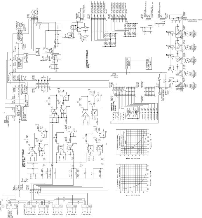
7. Electronic Circuit Diagram
13

8. Printed Circuit Board
8.1Main Printed Circuit Board
14

8.2Noise Filter Printed Circuit Board
8.3Display Printed Circuit Board
15
9. Installation Information
9.1Check Points
16

10. Installation Instruction
10.1 Select The Best Location
If an awning is built over the unit to prevent direct sunlight or rain, be careful that heat radiation from the condenser is not obstructed.
There should not be any animal or plant which could be affected by hot air discharged.
Keep the spaces indicated by arrows from wall, ceiling, fence or other obstacles.
Do not place any obstacles which may cause a short circuit of the discharged air.
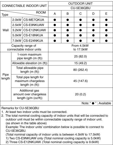
|
Refrigerant piping size |
|
|
|
|
Outdoor Unit |
CU-5E36*** |
|
|
|
|
Liquid - side |
ø1/4" (ø6.35 mm) thickness 1/32" (t0.8 mm) |
|
|
|
|
Gas - side |
ø3/8" (ø9.52 mm) thickness 1/32" (t0.8 mm) |
|
*(ø1/2" (ø12.7 mm) thickness 1/32" (t0.8 mm)) |
||
|
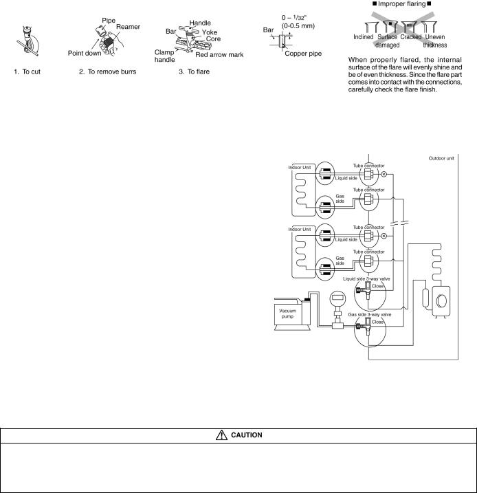
* In case of indoor is CS-E24***, then ø1/2" (ø12.7 mm) thickness 1/32" (t0.8 mm) gas-pipe size must be used together with CZ-MA2P (pipe size expander)
Outdoor Unit |
CU-5E36*** |
Min. total piping length for additional gas |
147.6 ft (45 m) |
If total piping length of all indoor units exceeds the minimum length listed above, additionally charge with 0.2 oz (20g) of refrigerant (R410A) for each additional feet (meter) of piping.
Allowable piping length
Outdoor Unit |
CU-5E36*** |
||
|
|
|
|
Allowable piping length of each indoor unit (min. ~ max.) |
9.8 ft ~ 82.0 ft (3 m ~ 25 m) |
||
|
|
|
|
Allowable total piping length of all indoor unit |
262.4 ft (80 m) or less |
||
|
|
|
|
Height difference between indoor and outdoor unit |
Outdoor unit located on upper side |
|
49.2 ft (15 m) or less |
|
|
|
|
Outdoor unit located otherwise |
|
24.6 ft (7.5 m) or less |
|
|
|
||
|
|
|
|
Height difference between indoor unit |
Outdoor unit located on upper side |
|
24.6 ft (7.5 m) or less |
|
|
|
|
Outdoor unit located otherwise |
|
49.2 ft (15 m) or less |
|
|
|
||
|
|
|
|
17
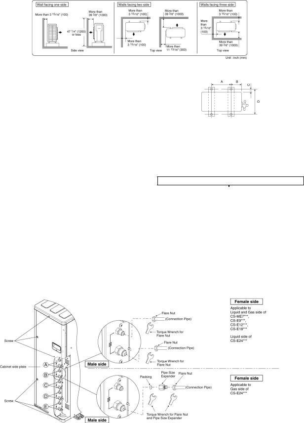
Outdoor Unit Installation Guidelines
Where a wall or other obstacle is in the path of outdoor unit’s intake or exhaust airflow, follow the installation guidelines below.
For any of the below installation patterns, the wall height on the exhaust side should be 47-1/4" (1200 mm) or less.
10.2 Install The Outdoor Unit
After selecting the best location, start installation to Indoor/Outdoor Unit Installation Diagram.
1.Fix the unit on concrete or rigid frame firmly and horizontally by bolt nut (ø13/32"
(ø10 mm)).
2.When installing at roof, please consider strong wind and earthquake.
Please fasten the installation stand firmly with bolt or nails.
Model |
A |
B |
C |
D |
|
|
|
|
|
|
|
CU-5E36*** |
24-13/32" |
6-11/16" |
25/32" |
14-31/32" |
|
(620 mm) |
(170 mm) |
(20 mm) |
(380.5 mm) |
||
|
10.3 Connect The Piping
Remove the cabinet side plate (metal) from the unit by loosening six screws.
Connecting The Piping To Outdoor Unit
Decide piping length and then cut by using pipe cutter.
Remove burrs from cut edge. Make flare after inserting the flare nut (locate at valve) onto the copper pipe.
Align center of piping to valves and then tighten with torque wrench to the specified torque as stated in the table.
Do not over tighten, over tightening may cause gas leakage
Piping size |
Torque |
1/4" [6.35 mm] |
[18 N•m (1.8 kgf.m)] |
3/8" [9.52 mm] |
[42 N•m (4.3 kgf.m)] |
1/2" [12.7 mm] |
[55 N•m (5.6 kgf.m)] |
5/8" [15.88 mm] |
[65 N•m (6.6 kgf.m)] |
3/4" [19.05 mm] |
[100 N•m (10.2 kgf.m)] |
Gas Leak Checking
Pressure test to system to 400 PSIG with dry nitrogen, in stages.
Thoroughly leak check the system.
If the pressure holds, release the nitrogen and proceed to section 10.4.
18
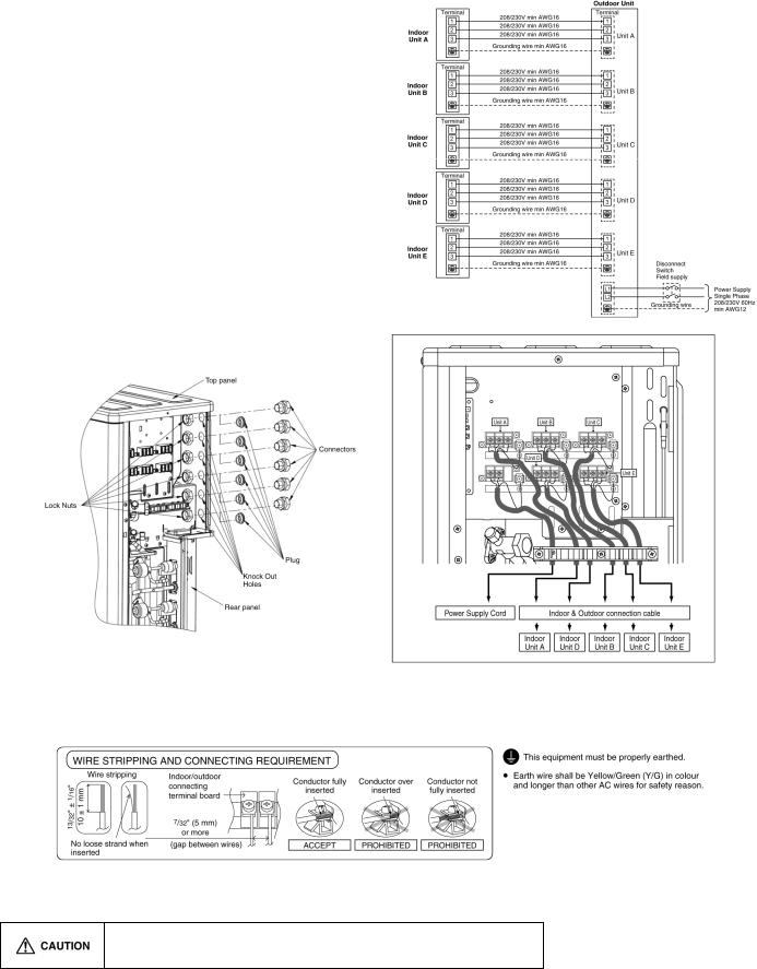
CUTTING AND FLARING THE PIPING
1.Please cut using pipe cutter and then remove the burrs.
2.Remove the burrs by using reamer. If burrs is not removed, gas leakage may be caused. Turn the piping end down to avoid the metal powder entering the pipe.
3.Please make flare after inserting the flare nut onto the copper pipes.
10.4 Evacuation Of The Equipment
WHEN INSTALLING AN AIR CONDITIONER, BE SURE TO EVACUATE THE AIR INSIDE THE INDOOR UNIT AND PIPES in the following procedure.
1.Connect a charging hose with a push pin to the Low side of a charging set and the service port of the gas side 3-way valve.
2.Connect the micron gauge between vacuum pump and service port of outdoor units.
3.Turn on the power switch of the vacuum pump and make sure that connect digital micron gauge and to pull down to a value of 500 microns.
4.To make sure micron gauge a value 500 microns and close the low side valve of the charging set and turn off the vacuum pump.
5.Disconnect the vacuum pump house from the service port of the 3-way valve.
6.Tighten the service port caps of gas side 3-way valve at a torque of 13.3 Ibf.ft (18 N•m) with a torque wrench.
7.Remove the valve caps of both of the 2-way valve and 3-way valve. Position both of the valves to “Open” using a hexagonal wrench (5/32" (4 mm)).
8.Mount valve caps onto the 2-way valve and 3-way valve.
o Be sure to check for gas leakage.
If micron gauge value does not descend 500 microns, take the following measures:
-If the leak stops when the piping connections are tightened further, continue working from step .
-If the leak does not stop when the connections are retightened, repair location of leak.
-Do not release refrigerant during piping work for installation and reinstallation.
-Take care of the liquid refrigerant, it may cause frostbite.
19
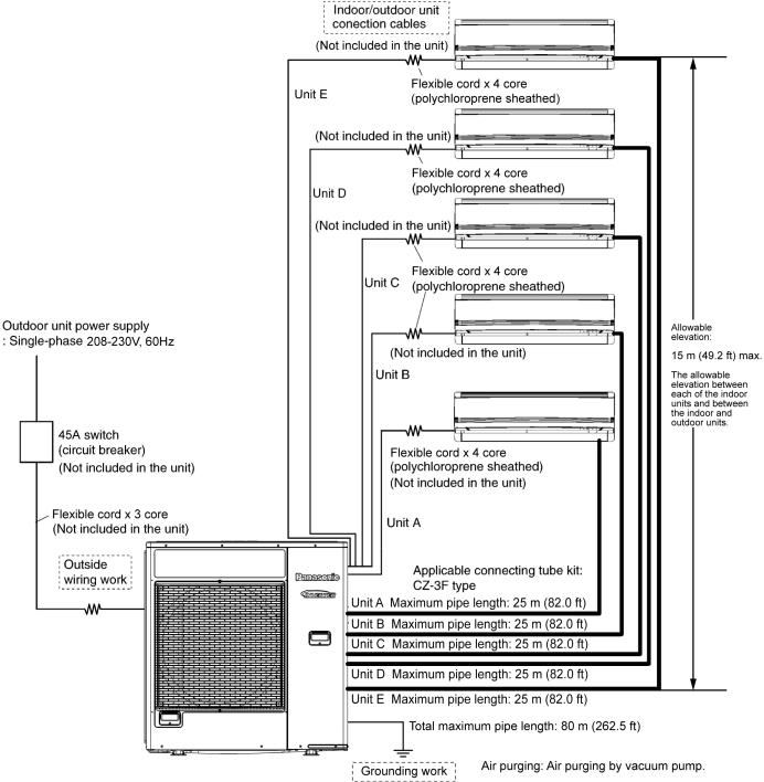
10.5Connect The Cable To The Outdoor Unit
1.Remove Plugs.
2.Fix the conduit connectors to the knock out holes with lock-nuts, then secure them.
3.Connecting wire between indoor unit and outdoor unit should be UL listed or CSA approved 4 conductor wires minimum AWG16 in accordance with local electric codes.
4.Wire Connection to the power supply (208/230V 60Hz) through circuit breaker.
o Connect the UL listed or CSA approved wires minimum AWG12 to the terminal board, and connect to other end of the wires to circuit breaker.
5.Connect the power supply cord and connecting wires between indoor unit and outdoor unit according to the diagram as shown.
6.For wire stripping and connection requirement, refer to the diagram below.
7.Secure the power supply cord and connection cables onto the control board with the holder.
8.Fix the cabinet side plate (metal) back to the original position with screws.
10.6Heat Insulation
Use a material with good heat-resistant properties as the heat insulation for the pipes. Be sure to insulate both the gas-side and liquid-side pipes. If the pipes are not adequately insulated, condensation or water leakages may occur.
Liquid-side pipes |
Material shall |
|
|
withstand 248°F |
|
Gas-side pipes |
||
(120°C) or higher |
||
|
|
20
10.7Disposal Of Outdoor Unit Drain Water
If a drain elbow is used, the unit should be placed on a stand which is taller than 1-31/32" (50 mm).
If the unit is used in an area where temperature falls below 32°F (0°C) for 2 or 3 days in succession, it is recommended not to use a drain elbow, for the drain water freezes and the fan will not rotate.
21
11. Operation Control
11.1 Cooling Operation
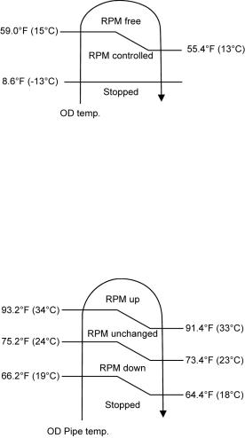
11.1.1Outdoor fan control
When cooling operation is enabled, based on outdoor ambient temperature, fan motor control will be adjusted according to figure below:
11.1.2Annual Cooling control
This control is to enable cooling operation when outdoor ambient temperature is low.
Control start conditions:
o Cooling operation is activated with compressor ON.
o Outdoor ambient temperature is less than 59°F (15°C).
Control contents:
o When the above conditions are fulfilled, based on outdoor pipe temperature, the outdoor fan motor will operate according to figure below:
To improve the judgment accuracy during annual cooling control, outdoor ambient temperature sampling for 2 minutes will be activated every 35 minutes under designated fan speed.
Control stop conditions:
o When either one of the start conditions are not complied.
11.1.3Cooling Powerful Operation 1
During cooling operation, this control is to concentrate outdoor unit capability to the powerful operation enabled indoor unit by temporary stop the capability supply to low load demand indoor units.
Operation start condition:
o Powerful operation ON for targeted indoor unit.
Operation content:
o If other indoor units (where Powerful operation are OFF) achieve setting temperature continuously for
1 minute after received powerful command from indoor unit, then capability supply to other indoor units are stopped for minimum 3 minutes.
Capability supply stop period follows powerful operation period.
Operation stops when comply either one of the following conditions:
o When other indoor units (where Powerful operation are OFF) is demand for capacity. o When the powerful operation is OFF for all indoor units.
o When Quiet operation received from 1 indoor unit. o When protection control starts.
22
 Loading...