


 Loading...
Cat. No. W341-E1-05
SYSMAC CS/CJ Series
CQM1H-PRO01-E/CQM1-PRO01-E/C200H-PRO27-E
Programming Consoles
OPERATION MANUAL
SYSMAC CS/CJ Series
CQM1H-PRO01-E/CQM1-PRO01-E/
C200H-PRO27-E
Programming Consoles
Operation Manual
Revised October 2005
Notice:
OMRON products are manufactured for use according to proper procedures by a qualified operator and only for the purposes described in this manual.
The following conventions are used to indicate and classify precautions in this manual. Always heed the information provided with them. Failure to heed precautions can result in injury to people or damage to property.
!DANGER Indicates an imminently hazardous situation which, if not avoided, will result in death or serious injury. Additionally, there may be severe property damage.
!WARNING Indicates a potentially hazardous situation which, if not avoided, could result in death or serious injury. Additionally, there may be severe property damage.
!Caution Indicates a potentially hazardous situation which, if not avoided, may result in minor or moderate injury, or property damage.
OMRON Product References
All OMRON products are capitalized in this manual. The word “Unit” is also capitalized when it refers to an OMRON product, regardless of whether or not it appears in the proper name of the product.
The abbreviation “Ch,” which appears in some displays and on some OMRON products, often means “word” and is abbreviated “Wd” in documentation in this sense.
The abbreviation “PLC” means Programmable Controller. “PC” is used, however, in some Programming Device displays to mean Programmable Controller.
Visual Aids
The following headings appear in the left column of the manual to help you locate different types of information.
Note Indicates information of particular interest for efficient and convenient operation of the product.
1,2,3... 1. Indicates lists of one sort or another, such as procedures, checklists, etc.
OMRON, 1999
All rights reserved. No part of this publication may be reproduced, stored in a retrieval system, or transmitted, in any form, or by any means, mechanical, electronic, photocopying, recording, or otherwise, without the prior written permission of OMRON.
No patent liability is assumed with respect to the use of the information contained herein. Moreover, because OMRON is constantly striving to improve its high-quality products, the information contained in this manual is subject to change without notice. Every precaution has been taken in the preparation of this manual. Nevertheless, OMRON assumes no responsibility for errors or omissions. Neither is any liability assumed for damages resulting from the use of the information contained in this publication.
v
Unit Versions of CS/CJ-series CPU Units
Unit Versions
A “unit version” has been introduced to manage CPU Units in the CS/CJ Series according to differences in functionality accompanying Unit upgrades. This applies to the CS1-H, CJ1-H, CJ1M, and CS1D CPU Units.
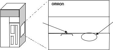
Notation of Unit Versions on Products
CS/CJ-series CPU Unit
The unit version is given to the right of the lot number on the nameplate of the products for which unit versions are being managed, as shown below.
Product nameplate
CS1H-CPU67H
CPU UNIT
Lot No. |
Unit version |
|
Example for Unit version 2.0 |
Lot No. 031001 0000 |
Ver.2.0 |
OMRON Corporation |
MADE IN JAPAN |
Confirming Unit Versions with Support Software
•CS1-H, CJ1-H, and CJ1M CPU Units (except for low-end models) manufactured on or before November 4, 2003 do not have a unit version given on the CPU Unit (i.e., the location for the unit version shown above is blank).
•The unit version of the CS1-H, CJ1-H, and CJ1M CPU Units, as well as the CS1D CPU Units for Single-CPU Systems, begins at version 2.0.
•The unit version of the CS1D CPU Units for Duplex-CPU Systems, begins at version 1.1.
•CPU Units for which a unit version is not given are called Pre-Ver. @.@
CPU Units, such as Pre-Ver. 2.0 CPU Units and Pre-Ver. 1.1 CPU Units.
CX-Programmer version 4.0 can be used to confirm the unit version using one of the following two methods.
•Using the PLC Information
•Using the Unit Manufacturing Information (This method can be used for Special I/O Units and CPU Bus Units as well.)
Note CX-Programmer version 3.3 or lower cannot be used to confirm unit versions.
PLC Information
•If you know the device type and CPU type, select them in the Change PLC Dialog Box, go online, and select PLC - Edit - Information from the menus.
•If you don’t know the device type and CPU type, but are connected directly to the CPU Unit on a serial line, select PLC - Auto Online to go online, and then select PLC - Edit - Information from the menus.
vi
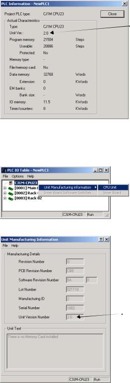
In either case, the following PLC Information Dialog Box will be displayed.
Unit version
Use the above display to confirm the unit version of the CPU Unit.
Unit Manufacturing Information
In the IO Table Window, right-click and select Unit Manufacturing information - CPU Unit.
The following Unit Manufacturing information Dialog Box will be displayed
Unit version
Use the above display to confirm the unit version of the CPU Unit connected online.
vii
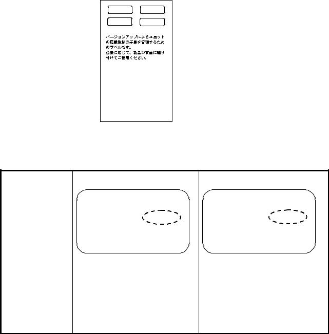
Using the Unit Version |
The following unit version labels are provided with the CPU Unit. |
|
Labels |
|
|
|
Ver. 2.0 |
Ver. |
|
Ver. 2.0 |
Ver. |
These Labels can be used to manage differences in the available functions among the Units . Place the approp riate label on the fro nt of the Unit to sho w what Unit version is actually being used .
These labels can be attached to the front of previous CPU Units to differentiate between CPU Units of different unit versions.
Unit Version Notation In this manual, the unit version of a CPU Unit is given as shown in the following table.
Product nameplate CPU Units on which no unit version is |
Units on which a version is given |
given |
(Ver. @.@) |
|
Lot No. XXXXXX XXXX |
Lot No. XXXXXX XXXX |
Ver.@ .@ |
|
|
OMRON Corporation MADE IN JAPAN |
OMRON Corporation |
MADE IN JAPAN |
|
Meaning |
|
|
|
|
|
|
|
|
|
Designating individual |
Pre-Ver. 2.0 |
CS1-H CPU Units |
CS1H-CPU67H CPU Unit Ver. @.@ |
|
CPU Units (e.g., the |
|
|
|
|
CS1H-CPU67H) |
|
|
|
|
|
|
|
|
|
Designating groups of |
Pre-Ver. 2.0 |
CS1-H CPU Units |
CS1-H CPU Units Ver. @.@ |
|
CPU Units (e.g., the |
|
|
|
|
CS1-H CPU Units) |
|
|
|
|
|
|
|
|
|
Designating an entire |
Pre-Ver. 2.0 |
CS-series CPU Units |
CS-series CPU Units Ver. @.@ |
|
series of CPU Units |
|
|
|
|
(e.g., the CS-series CPU |
|
|
|
|
Units) |
|
|
|
|
viii
Unit Versions and Lot Numbers
Series |
|
Model |
|
|
|
Data of manufacture |
|
||||||||
|
|
|
|
|
|
|
|
|
|
|
|
|
|
|
|
|
|
|
|
Earlier |
Sept. 2003 |
Oct. 2003 |
Nov. 2003 |
Dec. 2003 |
|
Later |
|||||
|
|
|
|
|
|
|
|
|
|
|
|
|
|
|
|
CS |
CS1 CPU Units |
CS1@-CPU@@ |
|
|
|
|
|
|
|
|
|
|
|
|
|
Series |
|
|
|
No unit version |
|
|
|
|
|
|
|
|
|
|
|
|
|
|
|
|
|
|
|
|
|
|
|
|
|
||
|
|
|
|
|
|
|
|
|
|
|
|
|
|
|
|
|
|
|
|
|
|
|
|
|
|
|
|
|
|
|
|
|
CS1-V1 CPU Units |
CS1@-CPU@@-V1 |
|
|
|
|
|
|
|
|
|
|
|
|
|
|
|
|
|
No unit version |
|
|
|
|
|
|
|
|
|
|
|
|
|
|
|
|
|
|
|
|
|
|
|
|
|
|
|
|
|
|
|
|
|
|
|
|
|
|
|
|
|
|
|
|
CS1-H CPU Units |
CS1@-CPU@@H |
|
|
|
|
|
|
|
|
|
|
|
|
|
|
|
|
|
Pre-Ver. 2.0 CPU Units |
|
|
|
CPU Units Ver. 2.0 |
|
||||||
|
|
|
|
|
|
|
(Lot No.: 031105 on) |
|
|||||||
|
|
|
|
|
|
|
|
|
|
||||||
|
|
|
|
|
|
|
|
|
|
|
|
|
|
|
|
|
CS1D |
CPU Units |
CS1D-CPU@@H |
|
|
|
|
|
|
|
|
|
|
|
|
|
CPU |
for Duplex- |
|
|
|
|
|
|
|
CPU Units Ver.1.1 |
|
||||
|
Units |
CPU Sys- |
|
Pre-Ver. 1.1 CPU Units |
|
|
|
|
|
||||||
|
|
|
|
|
|
(Lot No.: 031120 on) |
|
||||||||
|
|
tem |
|
|
|
|
|
|
|
|
|||||
|
|
|
|
|
|
|
|
|
|
|
|
|
|
|
|
|
|
CPU Units |
CS1D-CPU@@S |
|
|
|
|
|
|
|
|
|
|
|
|
|
|
for Single- |
|
|
|
|
|
|
|
|
|
|
CPU Units Ver. 2.0 |
||
|
|
CPU Sys- |
|
|
|
|
|
|
|
|
|
|
|||
|
|
|
|
|
|
|
|
|
|
|
|
(Lot No.: 031215 on) |
|||
|
|
tem |
|
|
|
|
|
|
|
|
|
|
|||
|
|
|
|
|
|
|
|
|
|
|
|
|
|
|
|
CJ |
CJ1 CPU Units |
CJ1G-CPU@@ |
|
|
|
|
|
|
|
|
|
|
|
|
|
Series |
|
|
|
Pre-Ver. 2.0 CPU Units |
|
|
|
|
|
|
|
|
|
|
|
|
|
|
|
|
|
|
|
|
|
|
|
|
|
||
|
|
|
|
|
|
|
|
|
|
|
|
|
|
|
|
|
|
|
|
|
|
|
|
|
|
|
|
|
|
|
|
|
CJ1-H CPU Units |
CJ1@-CPU@@H |
|
|
|
|
|
|
|
|
|
|
|
|
|
|
|
|
|
Pre-Ver. 2.0 CPU Units |
|
|
|
CPU Units Ver. 2.0 |
|
||||||
|
|
|
|
|
|
|
(Lot No.: 031105 on) |
|
|||||||
|
|
|
|
|
|
|
|
|
|
||||||
|
|
|
|
|
|
|
|
|
|
|
|
|
|
|
|
|
CJ1M CPU Units |
CJ1M-CPU@@ |
|
|
|
|
|
|
|
|
|
|
|
|
|
|
except low-end mod- |
|
|
|
|
|
|
CPU Units Ver. 2.0 |
|
||||||
|
els |
|
|
Pre-Ver. 2.0 CPU Units |
|
|
|
|
|||||||
|
|
|
|
|
|
(Lot No.: 031105 on) |
|
||||||||
|
|
|
|
|
|
|
|
|
|
||||||
|
|
|
|
|
|
|
|
|
|
|
|
|
|
|
|
|
CJ1M CPU Units, |
CJ1M-CPU11/21 |
|
|
|
|
|
|
|
|
|
|
|
|
|
|
low-end models |
|
|
|
|
Unit Ver. 2.0 |
|
||||||||
|
|
|
|
|
|
|
|
||||||||
|
|
|
|
|
|
|
(Lot No.: 031002 on) |
|
|||||||
|
|
|
|
|
|
|
|
|
|
|
|
|
|
|
|
Sup- |
CX-Programmer |
WS02-CXPC1-EV@ |
|
|
|
|
|
|
|
|
|
|
|
|
|
port |
|
|
|
Ver.3.2 |
|
Ver.3.3 |
|
|
|
|
Ver.4.0 |
|
|||
Soft- |
|
|
|
|
|
|
|
|
|
||||||
ware |
|
|
|
|
|
|
|
|
|
|
|
|
|
|
|
|
|
|
|
|
|
|
|
|
|
|
|
|
|
|
|
ix
Function Support by Unit Version
CS1-H CPU Units (CS1@-CPU@@H)
|
Function |
Unit version |
|
|
|
|
|
|
|
Pre-Ver. 2.0 CPU |
CPU Units Ver. 2.0 |
|
|
Units |
|
Downloading and Uploading Individual Tasks |
--- |
OK |
|
|
|
|
|
Improved Read Protection Using Passwords |
--- |
OK |
|
|
|
|
|
Write Protection from FINS Commands Sent to CPU Units via Net- |
--- |
OK |
|
works |
|
|
|
Online Network Connections without I/O Tables |
--- |
OK |
|
|
|
|
|
Communications through a Maximum of 8 Network Levels |
--- |
OK |
|
|
|
|
|
Connecting Online to PLCs via NS-series PTs |
OK from lot number |
OK |
|
|
|
030201 |
|
|
|
|
|
Setting First Slot Words |
OK for up to 8 groups |
OK for up to 64 groups |
|
|
|
|
|
Automatic Transfers at Power ON without a Parameter File |
--- |
OK |
|
|
|
|
|
Automatic Detection of I/O Allocation Method for Automatic Transfer |
--- |
--- |
|
at Power ON |
|
|
|
|
|
|
|
Operation Start/End Times |
--- |
OK |
|
|
|
|
|
New Applica- |
MILH, MILR, MILC |
--- |
OK |
tion Instructions |
|
|
|
=DT, <>DT, <DT, <=DT, >DT, >=DT |
--- |
OK |
|
|
|
|
|
|
BCMP2 |
--- |
OK |
|
|
|
|
|
GRY |
OK from lot number |
OK |
|
|
030201 |
|
|
|
|
|
|
TPO |
--- |
OK |
|
|
|
|
|
DSW, TKY, HKY, MTR, 7SEG |
--- |
OK |
|
|
|
|
|
EXPLT, EGATR, ESATR, ECHRD, ECHWR |
--- |
OK |
|
|
|
|
|
Reading/Writing CPU Bus Units with IORD/IOWR |
OK from lot number |
OK |
|
|
030418 |
|
|
|
|
|
|
PRV2 |
--- |
--- |
x
CS1D CPU Units
|
|
Function |
CS1D CPU Units for Duplex-CPU Systems |
CS1D CPU Units |
||
|
|
|
|
(CS1D-CPU@@H) |
for Single-CPU |
|
|
|
|
|
|
|
Systems |
|
|
|
|
|
|
(CS1D-CPU@@S) |
|
|
|
|
Pre-Ver. 1.1 CPU |
CPU Unit Ver. 1.1 |
CPU Unit Ver. 2.0 |
|
|
|
|
Units |
|
|
Functions |
|
Duplex CPU Units |
OK |
OK |
--- |
|
unique to |
|
|
|
|
|
|
|
Online Unit Replacement |
OK |
OK |
OK |
||
CS1D CPU |
|
|||||
|
|
|
|
|
|
|
|
Duplex Power Supply Units |
OK |
OK |
OK |
||
Units |
|
|||||
|
|
|
|
|
|
|
|
|
Duplex Controller Link Units |
OK |
OK |
OK |
|
|
|
|
|
|
|
|
|
|
Duplex Ethernet Units |
--- |
OK |
OK |
|
|
|
|
|
|
|
|
Downloading and Uploading Individual Tasks |
--- |
--- |
OK |
|||
|
|
|
|
|||
Improved Read Protection Using Passwords |
--- |
--- |
OK |
|||
|
|
|
|
|||
Write Protection from FINS Commands Sent |
--- |
--- |
OK |
|||
to CPU Units via Networks |
|
|
|
|||
|
|
|
|
|||
Online Network Connections without I/O |
--- |
--- |
OK |
|||
Tables |
|
|
|
|
|
|
|
|
|
|
|||
Communications through a Maximum of 8 |
--- |
--- |
OK |
|||
Network Levels |
|
|
|
|
|
|
|
|
|
|
|||
Connecting Online to PLCs via NS-series PTs |
--- |
--- |
OK |
|||
|
|
|
|
|||
Setting First Slot Words |
--- |
--- |
OK for up to 64 |
|||
|
|
|
|
|
|
groups |
|
|
|
|
|||
Automatic Transfers at Power ON without a |
--- |
--- |
OK |
|||
Parameter File |
|
|
|
|
|
|
Automatic Detection of I/O Allocation Method |
--- |
--- |
--- |
|||
for Automatic Transfer at Power ON |
|
|
|
|||
Operation Start/End Times |
--- |
OK |
OK |
|||
|
|
|
|
|
||
New Applica- |
MILH, MILR, MILC |
--- |
--- |
OK |
||
tion Instruc- |
|
|
|
|
|
|
|
=DT, <>DT, <DT, <=DT, >DT, |
--- |
--- |
OK |
||
tions |
|
|||||
|
>=DT |
|
|
|
||
|
|
|
|
|
|
|
|
|
BCMP2 |
--- |
--- |
OK |
|
|
|
|
|
|
|
|
|
|
GRY |
--- |
--- |
OK |
|
|
|
|
|
|
|
|
|
|
TPO |
--- |
--- |
OK |
|
|
|
|
|
|
|
|
|
|
DSW, TKY, HKY, MTR, 7SEG |
--- |
--- |
OK |
|
|
|
|
|
|
|
|
|
|
EXPLT, EGATR, ESATR, |
--- |
--- |
OK |
|
|
|
ECHRD, ECHWR |
|
|
|
|
|
|
Reading/Writing CPU Bus |
--- |
--- |
OK |
|
|
|
Units with IORD/IOWR |
|
|
|
|
|
|
PRV2 |
--- |
--- |
--- |
|
xi
CJ1-H/CJ1M CPU Units
|
Function |
CJ1-H CPU Units |
CJ1M CPU Units, |
CJ1M CPU |
|||
|
|
(CJ1@-CPU@@H) |
except low-end models |
Units, low-end |
|||
|
|
|
|
(CJ1M-CPU@@) |
models |
||
|
|
|
|
|
|
(CJ1M-CPU11/ |
|
|
|
|
|
|
|
21) |
|
|
|
|
|
|
|
|
|
|
|
Pre-Ver. 2.0 |
CPU Units Ver. |
Pre-Ver. 2.0 |
CPU Units Ver. |
CPU Units Ver. |
|
|
|
CPU Units |
2.0 |
CPU Units |
2.0 |
2.0 |
|
Downloading and Uploading |
--- |
OK |
--- |
OK |
OK |
||
Individual Tasks |
|
|
|
|
|
||
Improved Read Protection |
--- |
OK |
--- |
OK |
OK |
||
Using Passwords |
|
|
|
|
|
||
Write Protection from FINS |
--- |
OK |
--- |
OK |
OK |
||
Commands Sent to CPU Units |
|
|
|
|
|
||
via Networks |
|
|
|
|
|
||
Online Network Connections |
OK, but only if I/ |
OK |
OK, but only if I/ |
OK |
OK |
||
without I/O Tables |
O table alloca- |
|
O table alloca- |
|
|
||
|
|
tion at power |
|
tion at power |
|
|
|
|
|
ON is set |
|
ON is set |
|
|
|
|
|
|
|
|
|
||
Communications through a |
OK for up to 8 |
OK for up to 64 |
OK for up to 8 |
OK for up to 64 |
OK for up to 64 |
||
Maximum of 8 Network Levels |
groups |
groups |
groups |
groups |
groups |
||
|
|
|
|
|
|
||
Connecting Online to PLCs via |
OK from lot |
OK |
OK from lot |
OK |
OK |
||
NS-series PTs |
number 030201 |
|
number 030201 |
|
|
||
|
|
|
|
|
|
||
Setting First Slot Words |
--- |
OK |
--- |
OK |
OK |
||
|
|
|
|
|
|
||
Automatic Transfers at Power |
--- |
OK |
--- |
OK |
OK |
||
ON without a Parameter File |
|
|
|
|
|
||
|
|
|
|
|
|
||
Automatic Detection of I/O Allo- |
--- |
OK |
--- |
OK |
OK |
||
cation Method for Automatic |
|
|
|
|
|
||
Transfer at Power ON |
|
|
|
|
|
||
|
|
|
|
|
|
||
Operation Start/End Times |
--- |
OK |
--- |
OK |
OK |
||
|
|
|
|
|
|
|
|
New |
MILH, MILR, MILC |
--- |
OK |
--- |
OK |
OK |
|
Applica- |
|
|
|
|
|
|
|
=DT, <>DT, <DT, |
--- |
OK |
--- |
OK |
OK |
||
tion |
|||||||
<=DT, >DT, >=DT |
|
|
|
|
|
||
Instruc- |
|
|
|
|
|
|
|
BCMP2 |
--- |
OK |
OK |
OK |
OK |
||
tions |
|||||||
|
|
|
|
|
|
||
|
GRY |
OK from lot |
OK |
OK from lot |
OK |
OK |
|
|
|
number 030201 |
|
number 030201 |
|
|
|
|
|
|
|
|
|
|
|
|
TPO |
--- |
OK |
--- |
OK |
OK |
|
|
|
|
|
|
|
|
|
|
DSW, TKY, HKY, |
--- |
OK |
--- |
OK |
OK |
|
|
MTR, 7SEG |
|
|
|
|
|
|
|
EXPLT, EGATR, |
--- |
OK |
--- |
OK |
OK |
|
|
ESATR, ECHRD, |
|
|
|
|
|
|
|
ECHWR |
|
|
|
|
|
|
|
Reading/Writing |
--- |
OK |
--- |
OK |
OK |
|
|
CPU Bus Units with |
|
|
|
|
|
|
|
IORD/IOWR |
|
|
|
|
|
|
|
PRV2 |
--- |
--- |
--- |
OK, but only for |
OK, but only for |
|
|
|
|
|
|
models with |
models with |
|
|
|
|
|
|
built-in I/O |
built-in I/O |
|
xii
Unit Versions and Programming Devices
CX-Programmer version 4.0 or higher must be used to enable using the functions added for CPU Unit Ver. 2.0. The following tables show the relationship between unit versions and CX-Programmer versions.
Unit Versions and Programming Devices
CPU Unit |
Functions |
|
|
|
CX-Programmer |
Program- |
|||||
|
|
|
|
|
|
|
|
|
|
|
ming Con- |
|
|
|
|
|
|
|
Ver. 3.2 |
Ver. 3.3 |
Ver. 4.0 |
||
|
|
|
|
|
|
|
sole |
||||
|
|
|
|
|
|
|
or lower |
|
or higher |
||
|
|
|
|
|
|
|
|
|
|||
CJ1M CPU Units, low- |
Functions added for |
Using new functions |
|
--- |
|
--- |
OK |
No |
|||
end models, Unit Ver. 2.0 |
unit version 2.0 |
|
|
|
|
|
|
|
restrictions |
||
Not using new functions |
|
--- |
|
OK |
OK |
||||||
|
|
|
|
|
|
|
|||||
|
|
|
|
|
|
|
|
|
|
|
|
CS1-H, CJ1-H, and |
Functions added for |
Using new functions |
|
--- |
|
--- |
OK |
|
|||
CJ1M CPU Units except |
unit version 2.0 |
|
|
|
|
|
|
|
|
||
Not using new functions |
|
OK |
|
OK |
OK |
|
|||||
low-end models, Unit Ver. |
|
|
|
|
|||||||
|
|
|
|
|
|
|
|
|
|||
2.0 |
|
|
|
|
|
|
|
|
|
|
|
|
|
|
|
|
|
|
|
|
|
|
|
CS1D CPU Units for Sin- |
Functions added for |
Using new functions |
|
--- |
|
--- |
OK |
|
|||
gle-CPU Systems, Unit |
unit version 2.0 |
|
|
|
|
|
|
|
|
||
Not using new functions |
|
|
|
|
|
|
|||||
Ver. 2.0 |
|
|
|
|
|
|
|
|
|||
|
|
|
|
|
|
|
|
|
|
||
|
|
|
|
|
|
|
|
|
|
|
|
CS1D CPU Units for |
Functions added for |
Using new functions |
|
--- |
|
--- |
OK |
|
|||
Duplex-CPU Systems, |
unit version 1.1 |
|
|
|
|
|
|
|
|
||
Not using new functions |
|
OK |
|
OK |
OK |
|
|||||
Unit Ver.1. |
|
|
|
|
|
||||||
|
|
|
|
|
|
|
|
|
|
||
|
|
|
Note As shown above, there is no need to upgrade to CX-Programmer version 4.0 |
||||||||
|
|
|
as long as the functions added for unit version 2.0 or unit version 1.1 are not |
||||||||
|
|
|
used. |
|
|
|
|
|
|
|
|
Device Type Setting |
The unit version does not affect the setting made for the device type on the |
||||||||||
|
|
|
CX-Programmer. Select the device type as shown in the following table |
||||||||
|
|
|
regardless of the unit version of the CPU Unit. |
|
|
||||||
|
|
|
|
|
|
|
|
||||
Series |
|
CPU Unit group |
|
CPU Unit model |
|
Device type setting on |
|||||
|
|
|
|
|
|
|
|
CX-Programmer Ver. 4.0 or higher |
|||
CS Series |
CS1-H CPU Units |
|
CS1G-CPU@@H |
|
CS1G-H |
|
|
||||
|
|
|
|
|
CS1H-CPU@@H |
|
CS1H-H |
|
|
||
|
|
CS1D CPU Units for Duplex-CPU Systems |
CS1D-CPU@@H |
|
CS1D-H (or CS1H-H) |
|
|||||
|
|
CS1D CPU Units for Single-CPU Systems |
CS1D-CPU@@S |
|
CS1D-S |
|
|
||||
CJ Series |
CJ1-H CPU Units |
|
CJ1G-CPU@@H |
|
CJ1G-H |
|
|
||||
|
|
|
|
|
CJ1H-CPU@@H |
|
CJ1H-H |
|
|
||
|
|
CJ1M CPU Units |
|
CJ1M-CPU@@ |
|
CJ1M |
|
|
|||
xiii
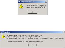
Troubleshooting Problems with Unit Versions on the CX-Programmer
Problem |
Cause |
Solution |
|
An attempt was made using CX- |
Check the program or change |
|
Programmer version 4.0 or higher |
the CPU Unit being down- |
|
to download a program contain- |
loaded to a CPU Unit Ver. 2.0 |
|
ing instructions supported only by |
or later. |
|
CPU Units Ver. 2.0 or later to a |
|
After the above message is displayed, a compiling |
Pre-Ver. 2.0 CPU Units. |
|
|
|
|
error will be displayed on the Compile Tab Page in the |
|
|
Output Window. |
|
|
|
|
|
|
An attempt was made using CX- |
Check the settings in the PLC |
|
Programmer version 4.0 or higher |
Setup or change the CPU Unit |
|
to download a PLC Setup con- |
being downloaded to a CPU |
|
taining settings supported only by |
Unit Ver. 2.0 or later. |
|
CPU Units Ver. 2.0 or later (i.e., |
|
|
not set to their default values) to a |
|
|
Pre-Ver. 2.0 CPU Units. |
|
|
|
|
“????” is displayed in a program transferred from the |
CX-Programmer version 3.3 or |
The new instructions cannot |
PLC to the CX-Programmer. |
lower was used to upload a pro- |
be uploaded using CX-Pro- |
|
gram containing instructions sup- |
grammer version 3.3 or lower. |
|
ported only by CPU Units Ver. 2.0 |
Use CX-Programmer version |
|
or later from a CPU Unit Ver. 2.0 |
4.0 or higher. |
|
or later. |
|
xiv
TABLE OF CONTENTS
PRECAUTIONS . . . . . . . . . . . . . . . . . . . . . . . . . . . . . . . . . . . |
xxiii |
|
1 |
Intended Audience . . . . . . . . . . . . . . . . . . . . . . . . . . . . . . . . . . . . . . . . . . . . . . . . . . . . . . . . |
xxiv |
2 |
General Precautions . . . . . . . . . . . . . . . . . . . . . . . . . . . . . . . . . . . . . . . . . . . . . . . . . . . . . . . |
xxiv |
3 |
Safety Precautions. . . . . . . . . . . . . . . . . . . . . . . . . . . . . . . . . . . . . . . . . . . . . . . . . . . . . . . . . |
xxiv |
4 |
Operating Environment Precautions . . . . . . . . . . . . . . . . . . . . . . . . . . . . . . . . . . . . . . . . . . . |
xxv |
5 |
Application Precautions . . . . . . . . . . . . . . . . . . . . . . . . . . . . . . . . . . . . . . . . . . . . . . . . . . . . |
xxvi |
SECTION 1 |
|
|
Installation. . . . . . . . . . . . . . . . . . . . . . . . . . . . . . . . . . . . . . . . |
1 |
|
1-1 |
Applicable Models . . . . . . . . . . . . . . . . . . . . . . . . . . . . . . . . . . . . . . . . . . . . . . . . . . . . . . . . |
2 |
1-2 Using the Programming Console . . . . . . . . . . . . . . . . . . . . . . . . . . . . . . . . . . . . . . . . . . . . . |
3 |
|
1-3 |
Programming Console Functions . . . . . . . . . . . . . . . . . . . . . . . . . . . . . . . . . . . . . . . . . . . . . |
5 |
1-4 |
Unsupported Functions . . . . . . . . . . . . . . . . . . . . . . . . . . . . . . . . . . . . . . . . . . . . . . . . . . . . . |
7 |
1-5 |
Functions and Nomenclature . . . . . . . . . . . . . . . . . . . . . . . . . . . . . . . . . . . . . . . . . . . . . . . . |
7 |
1-6 Programming Console Connection and Installation . . . . . . . . . . . . . . . . . . . . . . . . . . . . . . . |
14 |
|
1-7 Comparison with Previous Models . . . . . . . . . . . . . . . . . . . . . . . . . . . . . . . . . . . . . . . . . . . . |
16 |
|
SECTION 2 |
|
|
Using the Programming Console . . . . . . . . . . . . . . . . . . . . . |
17 |
|
2-1 |
Programming. . . . . . . . . . . . . . . . . . . . . . . . . . . . . . . . . . . . . . . . . . . . . . . . . . . . . . . . . . . . . |
18 |
2-2 Connecting the Programming Console . . . . . . . . . . . . . . . . . . . . . . . . . . . . . . . . . . . . . . . . . |
19 |
|
2-3 Using the Programming Console for the First Time . . . . . . . . . . . . . . . . . . . . . . . . . . . . . . . |
19 |
|
2-4 |
Inputting Programs . . . . . . . . . . . . . . . . . . . . . . . . . . . . . . . . . . . . . . . . . . . . . . . . . . . . . . . . |
22 |
2-5 |
Checking Program Operation . . . . . . . . . . . . . . . . . . . . . . . . . . . . . . . . . . . . . . . . . . . . . . . . |
26 |
SECTION 3 |
|
|
Operation. . . . . . . . . . . . . . . . . . . . . . . . . . . . . . . . . . . . . . . . . |
31 |
|
3-1 |
Starting Operation . . . . . . . . . . . . . . . . . . . . . . . . . . . . . . . . . . . . . . . . . . . . . . . . . . . . . . . . . |
32 |
3-2 |
Changing Operating Modes . . . . . . . . . . . . . . . . . . . . . . . . . . . . . . . . . . . . . . . . . . . . . . . . . |
35 |
3-3 |
Key Functions . . . . . . . . . . . . . . . . . . . . . . . . . . . . . . . . . . . . . . . . . . . . . . . . . . . . . . . . . . . . |
36 |
3-4 |
Clearing Memory Areas . . . . . . . . . . . . . . . . . . . . . . . . . . . . . . . . . . . . . . . . . . . . . . . . . . . . |
37 |
3-5 |
Buzzer Operation . . . . . . . . . . . . . . . . . . . . . . . . . . . . . . . . . . . . . . . . . . . . . . . . . . . . . . . . . |
42 |
3-6 |
Selecting Tasks . . . . . . . . . . . . . . . . . . . . . . . . . . . . . . . . . . . . . . . . . . . . . . . . . . . . . . . . . . . |
43 |
3-7 |
I/O Table Operations . . . . . . . . . . . . . . . . . . . . . . . . . . . . . . . . . . . . . . . . . . . . . . . . . . . . . . . |
46 |
SECTION 4 |
|
|
Writing and Editing Programs . . . . . . . . . . . . . . . . . . . . . . . |
53 |
|
4-1 |
Inputting Instructions . . . . . . . . . . . . . . . . . . . . . . . . . . . . . . . . . . . . . . . . . . . . . . . . . . . . . . |
54 |
4-2 Reading and Searching Programs . . . . . . . . . . . . . . . . . . . . . . . . . . . . . . . . . . . . . . . . . . . . . |
67 |
|
4-3 |
Editing Programs. . . . . . . . . . . . . . . . . . . . . . . . . . . . . . . . . . . . . . . . . . . . . . . . . . . . . . . . . . |
71 |
xv
TABLE OF CONTENTS
SECTION 5 |
|
|
Checking and Adjusting Programs . . . . . . . . . . . . . . . . . . . . |
79 |
|
5-1 |
Reading Program Execution Status . . . . . . . . . . . . . . . . . . . . . . . . . . . . . . . . . . . . . . . . . . . . |
80 |
5-2 |
Simple I/O Monitor . . . . . . . . . . . . . . . . . . . . . . . . . . . . . . . . . . . . . . . . . . . . . . . . . . . . . . . . |
81 |
5-3 |
I/O Multipoint Monitor . . . . . . . . . . . . . . . . . . . . . . . . . . . . . . . . . . . . . . . . . . . . . . . . . . . . . |
87 |
5-4 |
Monitor Display Format . . . . . . . . . . . . . . . . . . . . . . . . . . . . . . . . . . . . . . . . . . . . . . . . . . . . |
90 |
5-5 |
Changing Word (16-bit) Present Values . . . . . . . . . . . . . . . . . . . . . . . . . . . . . . . . . . . . . . . . |
95 |
5-6 |
Forcing Bits ON/OFF . . . . . . . . . . . . . . . . . . . . . . . . . . . . . . . . . . . . . . . . . . . . . . . . . . . . . . |
101 |
5-7 |
Differential Monitor. . . . . . . . . . . . . . . . . . . . . . . . . . . . . . . . . . . . . . . . . . . . . . . . . . . . . . . . |
103 |
5-8 |
Online Editing . . . . . . . . . . . . . . . . . . . . . . . . . . . . . . . . . . . . . . . . . . . . . . . . . . . . . . . . . . . . |
104 |
SECTION 6 |
|
|
Maintenance Operations . . . . . . . . . . . . . . . . . . . . . . . . . . . . |
115 |
|
6-1 |
Clock Read/Change . . . . . . . . . . . . . . . . . . . . . . . . . . . . . . . . . . . . . . . . . . . . . . . . . . . . . . . . |
116 |
6-2 |
Cycle Time Read . . . . . . . . . . . . . . . . . . . . . . . . . . . . . . . . . . . . . . . . . . . . . . . . . . . . . . . . . . |
117 |
6-3 |
Reading/Clearing Error Messages . . . . . . . . . . . . . . . . . . . . . . . . . . . . . . . . . . . . . . . . . . . . . |
118 |
SECTION 7 |
|
|
Memory Card Operations . . . . . . . . . . . . . . . . . . . . . . . . . . . |
123 |
|
7-1 |
File Memory Operations . . . . . . . . . . . . . . . . . . . . . . . . . . . . . . . . . . . . . . . . . . . . . . . . . . . . |
124 |
7-2 |
Memory Card Format . . . . . . . . . . . . . . . . . . . . . . . . . . . . . . . . . . . . . . . . . . . . . . . . . . . . . . |
125 |
7-3 |
File Write. . . . . . . . . . . . . . . . . . . . . . . . . . . . . . . . . . . . . . . . . . . . . . . . . . . . . . . . . . . . . . . . |
126 |
7-4 |
File Read . . . . . . . . . . . . . . . . . . . . . . . . . . . . . . . . . . . . . . . . . . . . . . . . . . . . . . . . . . . . . . . . |
130 |
7-5 |
File Verify . . . . . . . . . . . . . . . . . . . . . . . . . . . . . . . . . . . . . . . . . . . . . . . . . . . . . . . . . . . . . . . |
134 |
7-6 |
File Delete . . . . . . . . . . . . . . . . . . . . . . . . . . . . . . . . . . . . . . . . . . . . . . . . . . . . . . . . . . . . . . . |
137 |
SECTION 8 |
|
|
PLC Setup Procedure. . . . . . . . . . . . . . . . . . . . . . . . . . . . . . . |
141 |
|
8-1 |
PLC Setup Procedure. . . . . . . . . . . . . . . . . . . . . . . . . . . . . . . . . . . . . . . . . . . . . . . . . . . . . . . |
142 |
Appendices |
|
|
A |
ASCII Coding Sheet . . . . . . . . . . . . . . . . . . . . . . . . . . . . . . . . . . . . . . . . . . . . . . . . . . . . . . . |
145 |
B |
Error Messages . . . . . . . . . . . . . . . . . . . . . . . . . . . . . . . . . . . . . . . . . . . . . . . . . . . . . . . . . . . |
147 |
C PLC Setup Coding Sheets for Programming Console . . . . . . . . . . . . . . . . . . . . . . . . . . . . . |
149 |
|
Index. . . . . . . . . . . . . . . . . . . . . . . . . . . . . . . . . . . . . . . . . . . . . |
161 |
|
Revision History . . . . . . . . . . . . . . . . . . . . . . . . . . . . . . . . . . . |
165 |
|
xvi
About this Manual:
This manual describes the installation and operation of the CQM1H-PRO01-E, CQM1-PRO01-E and C200H-PRO27-E Programming Consoles for use with CS-series and CJ-series Programmable Controllers and includes the sections described below. The CS Series and CJ Series are subdivided as shown in the following table.
Unit |
CS Series |
CJ Series |
|
|
|
CPU Units |
CS1-H CPU Units: CS1H-CPU@@H |
CJ1-H CPU Units: CJ1H-CPU@@H |
|
CS1G-CPU@@H |
CJ1G-CPU@@H |
|
|
|
|
CS1 CPU Units: CS1H-CPU@@-EV1 |
CJ1 CPU Units: CJ1G-CPU@@-EV1 |
|
CS1G-CPU@@-EV1 |
CJ1M CPU Units: CJ1M-CPU@@ |
|
|
|
|
CS1D CPU Units: |
|
|
CS1D CPU Units for Duplex-CPU Systems: |
|
|
CS1D-CPU@@H |
|
|
CS1D CPU Units for Single-CPU Systems: |
|
|
CS1D-CPU@@S |
|
|
CS1D Process CPU Units: |
|
|
CS1D-CPU@@P |
|
|
|
|
Basic I/O Units |
CS-series Basic I/O Units |
CJ-series Basic I/O Units |
|
|
|
Special I/O Units |
CS-series Special I/O Units |
CJ-series Special I/O Units |
|
|
|
CPU Bus Units |
CS-series CPU Bus Units |
CJ-series CPU Bus Units |
|
|
|
Power Supply Units |
CS-series Power Supply Units |
CJ-series Power Supply Units |
|
Note: Use the special CS1D Power Supply |
|
|
Units for CS1D PLCs. |
|
|
|
|
Please read this manual and all related manuals listed in the table on the next page carefully and be sure you understand the information provided before attempting to use the CQM1H-PRO01-E, CQM1- PRO01-E, or C200H-PRO27-E Programming Console to program, set up, or operate a PLC System.
Section 1 gives a brief overview of the functions performed by the Programming Console, as well as Programming Console specifications and connection procedures. It also lists the differences between the operation of the Programming Consoles for CS/CJ-series PLCs and previous Programming Consoles.
Section 2 provides information on how to set up the Programming Console for operation. It also describes how to write a simple program from the Programming Console.
Section 3 describes the basic operations of the Programming Console, including initializing memory and creating I/O tables. The three input modes available on the Programming Console are also described.
Section 4 describes how to create and edit programs from the Programming Console.
Section 5 describes how to monitor programs in different display modes to check and modify the user programs. Change values from various displays is also described.
Section 6 includes information on reading and setting the clock, reading the cycle time, and reading/ clearing error messages.
Section 7 provides information on how to format Memory Cards before use, and procedures for transferring data between Memory Cards and the CPU Unit.
Section 8 lists the settings in the PLC Setup.
Appendix A provides a ASCII coding list, Appendix B provides a list of operating error messages, and Appendix C provides a PLC Setup Setting Sheets.
xvii

About this Manual, Continued
Name |
Cat. No. |
Contents |
|
|
|
SYSMAC CS/CJ Series |
W341 |
Provides information on how to program and operate |
Programming Consoles Operation Manual |
|
CS/CJ-series PLCs using a Programming Console. |
CQM1H-PRO01-E, CQM1-PRO01-E, |
|
(This manual) |
C200H-PRO27-E |
|
|
|
|
|
SYSMAC CS Series |
W339 |
Describes the installation and operation of the CS- |
CS1G/H-CPU@@-EV1, CS1G/H-CPU@@H |
|
series PLCs. |
Programmable Controllers Operation Manual |
|
|
|
|
|
SYSMAC CJ Series |
W393 |
Describes the installation and operation of the CJ-series |
CJ1G-CPU@@, CJ1G/H-CPU@@H |
|
PLCs. |
Programmable Controllers Operation Manual |
|
|
|
|
|
SYSMAC CS Series |
W405 |
Describes the installation and operation of the Duplex |
CS1D-CPU@@H CPU Units |
|
System based on CS1D CPU Units. |
CS1D-CPU@@S CPU Units |
|
|
CS1D-DPL01 Duplex Unit |
|
|
CS1D-PA/PD@@@ Power Supply Unit |
|
|
Duplex System Operation Manual |
|
|
|
|
|
SYSMAC CS/CJ Series |
W394 |
Describes the ladder diagram programming functions |
CS1G/H-CPU@@-EV1, CS1G/H-CPU@@H, |
|
and other functions supported by CS-series and CJ- |
CS1D-CPU@@H/S, CJ1G-CPU@@, |
|
series PLCs. |
CJ1G/H-CPU@@H |
|
|
Programmable Controllers Programming Manual |
|
|
|
|
|
SYSMAC CS/CJ Series |
W340 |
Describes the ladder diagram programming instructions |
CS1G/H-CPU@@-EV1, CS1G/H-CPU@@H, |
|
supported by CS-series and CJ-series PLCs. |
CS1D-CPU@@H/S, CJ1G-CPU@@, |
|
|
CJ1G/H-CPU@@H |
|
|
Programmable Controllers |
|
|
Instructions Reference Manual |
|
|
|
|
|
SYSMAC |
W414 |
Provides information on how to use the CX-Program- |
CX-Programmer Operation Manual |
|
mer, a programming device that supports the CS/CJ- |
WS02-CXP@@-E |
|
series PLCs, and the CX-Net contained within CX-Pro- |
SYSMAC |
W425 |
grammer. |
CX-Programmer Operation Manual |
|
|
WS02-CXP@@-EV4 |
|
|
!WARNING Failure to read and understand the information provided in this manual may result in personal injury or death, damage to the product, or product failure. Please read each section in its entirety and be sure you understand the information provided in the section and related sections before attempting any of the procedures or operations given.
xviii

Read and Understand this Manual
Please read and understand this manual before using the product. Please consult your OMRON representative if you have any questions or comments.
Warranty and Limitations of Liability
WARRANTY
OMRON's exclusive warranty is that the products are free from defects in materials and workmanship for a period of one year (or other period if specified) from date of sale by OMRON.
OMRON MAKES NO WARRANTY OR REPRESENTATION, EXPRESS OR IMPLIED, REGARDING NONINFRINGEMENT, MERCHANTABILITY, OR FITNESS FOR PARTICULAR PURPOSE OF THE PRODUCTS. ANY BUYER OR USER ACKNOWLEDGES THAT THE BUYER OR USER ALONE HAS DETERMINED THAT THE PRODUCTS WILL SUITABLY MEET THE REQUIREMENTS OF THEIR INTENDED USE. OMRON DISCLAIMS ALL OTHER WARRANTIES, EXPRESS OR IMPLIED.
LIMITATIONS OF LIABILITY
OMRON SHALL NOT BE RESPONSIBLE FOR SPECIAL, INDIRECT, OR CONSEQUENTIAL DAMAGES, LOSS OF PROFITS OR COMMERCIAL LOSS IN ANY WAY CONNECTED WITH THE PRODUCTS, WHETHER SUCH CLAIM IS BASED ON CONTRACT, WARRANTY, NEGLIGENCE, OR STRICT LIABILITY.
In no event shall the responsibility of OMRON for any act exceed the individual price of the product on which liability is asserted.
IN NO EVENT SHALL OMRON BE RESPONSIBLE FOR WARRANTY, REPAIR, OR OTHER CLAIMS REGARDING THE PRODUCTS UNLESS OMRON'S ANALYSIS CONFIRMS THAT THE PRODUCTS WERE PROPERLY HANDLED, STORED, INSTALLED, AND MAINTAINED AND NOT SUBJECT TO CONTAMINATION, ABUSE, MISUSE, OR INAPPROPRIATE MODIFICATION OR REPAIR.
xix

Application Considerations
SUITABILITY FOR USE
OMRON shall not be responsible for conformity with any standards, codes, or regulations that apply to the combination of products in the customer's application or use of the products.
At the customer's request, OMRON will provide applicable third party certification documents identifying ratings and limitations of use that apply to the products. This information by itself is not sufficient for a complete determination of the suitability of the products in combination with the end product, machine, system, or other application or use.
The following are some examples of applications for which particular attention must be given. This is not intended to be an exhaustive list of all possible uses of the products, nor is it intended to imply that the uses listed may be suitable for the products:
•Outdoor use, uses involving potential chemical contamination or electrical interference, or conditions or uses not described in this manual.
•Nuclear energy control systems, combustion systems, railroad systems, aviation systems, medical equipment, amusement machines, vehicles, safety equipment, and installations subject to separate industry or government regulations.
•Systems, machines, and equipment that could present a risk to life or property.
Please know and observe all prohibitions of use applicable to the products.
NEVER USE THE PRODUCTS FOR AN APPLICATION INVOLVING SERIOUS RISK TO LIFE OR PROPERTY WITHOUT ENSURING THAT THE SYSTEM AS A WHOLE HAS BEEN DESIGNED TO ADDRESS THE RISKS, AND THAT THE OMRON PRODUCTS ARE PROPERLY RATED AND INSTALLED FOR THE INTENDED USE WITHIN THE OVERALL EQUIPMENT OR SYSTEM.
PROGRAMMABLE PRODUCTS
OMRON shall not be responsible for the user's programming of a programmable product, or any consequence thereof.
xx

Disclaimers
CHANGE IN SPECIFICATIONS
Product specifications and accessories may be changed at any time based on improvements and other reasons.
It is our practice to change model numbers when published ratings or features are changed, or when significant construction changes are made. However, some specifications of the products may be changed without any notice. When in doubt, special model numbers may be assigned to fix or establish key specifications for your application on your request. Please consult with your OMRON representative at any time to confirm actual specifications of purchased products.
DIMENSIONS AND WEIGHTS
Dimensions and weights are nominal and are not to be used for manufacturing purposes, even when tolerances are shown.
PERFORMANCE DATA
Performance data given in this manual is provided as a guide for the user in determining suitability and does not constitute a warranty. It may represent the result of OMRON's test conditions, and the users must correlate it to actual application requirements. Actual performance is subject to the OMRON Warranty and Limitations of Liability.
ERRORS AND OMISSIONS
The information in this manual has been carefully checked and is believed to be accurate; however, no responsibility is assumed for clerical, typographical, or proofreading errors, or omissions.
xxi
PRECAUTIONS
This section provides general precautions for using the Programmable Controller (PLC) and related devices.
The information contained in this section is important for the safe and reliable application of the Programmable Controller. You must read this section and understand the information contained before attempting to set up or operate a PLC system.
1 |
Intended Audience . . . . . . . . . . . . . . . . . . . . . . . . . . . . . . . . . . . . . . . . . . . . . |
xxiv |
2 |
General Precautions . . . . . . . . . . . . . . . . . . . . . . . . . . . . . . . . . . . . . . . . . . . . |
xxiv |
3 |
Safety Precautions. . . . . . . . . . . . . . . . . . . . . . . . . . . . . . . . . . . . . . . . . . . . . . |
xxiv |
4 |
Operating Environment Precautions . . . . . . . . . . . . . . . . . . . . . . . . . . . . . . . . |
xxv |
5 |
Application Precautions . . . . . . . . . . . . . . . . . . . . . . . . . . . . . . . . . . . . . . . . . |
xxvi |
xxiii

Intended Audience |
1 |
1 Intended Audience
This manual is intended for the following personnel, who must also have knowledge of electrical systems (an electrical engineer or the equivalent).
•Personnel in charge of designing FA systems.
•Personnel in charge of managing FA systems and facilities.
2 General Precautions
The user must operate the product according to the performance specifications described in the operation manuals.
Before using the product under conditions which are not described in the manual or applying the product to nuclear control systems, railroad systems, aviation systems, vehicles, combustion systems, medical equipment, amusement machines, safety equipment, and other systems, machines, and equipment that may have a serious influence on lives and property if used improperly, consult your OMRON representative.
Make sure that the ratings and performance characteristics of the product are sufficient for the systems, machines, and equipment, and be sure to provide the systems, machines, and equipment with double safety mechanisms.
This manual provides information for programming and operating the Unit. Be sure to read this manual before attempting to use the Unit and keep this manual close at hand for reference during operation.
!WARNING It is extremely important that a PLC and all PLC Units be used for the specified purpose and under the specified conditions, especially in applications that can directly or indirectly affect human life. You must consult with your OMRON representative before applying a PLC System to the above-mentioned applications.
3 Safety Precautions
!WARNING Do not attempt to take any Unit apart while the power is being supplied. Doing so may result in electric shock.
!WARNING Do not attempt to disassemble, repair, or modify any Units. Any attempt to do so may result in malfunction, fire, or electric shock.
!Caution The CPU Unit refreshes I/O even when operation has been stopped in PROGRAM mode. Always confirm safety before changing data in the output area allocated to the Output Units or changing data in any memory area allocated to Special I/O Units or CPU Bus Units using any of the following operations. The loads connected to the Output Units, Special I/O Units, or CPU Bus Units may operate unexpectedly.
•Transferring I/O memory to the CPU Unit using a peripheral device (personal computer software).
•Changing the present value using a peripheral device.
•Force-setting/resetting using a peripheral device.
•Transferring I/O memory files to the CPU Unit from the Memory Card or EM File Memory.
xxiv

Operating Environment Precautions |
4 |
•Transferring I/O memory data from other personal computers or host computers on the network.
!Caution Confirm that the equipment is operating safely before starting actual operation.
!Caution Execute online edit only after confirming that no adverse effects will be caused by extending the cycle time. Otherwise, the input signals may not be readable.
!Caution Confirm that no adverse effect will occur in the system before executing online edit.
4 Operating Environment Precautions
!Caution Do not operate the control system in the following places:
•Locations subject to direct sunlight.
•Locations subject to temperatures or humidity outside the range specified in the specifications.
•Locations subject to condensation as the result of severe changes in temperature.
•Locations subject to corrosive or flammable gases.
•Locations subject to dust (especially iron dust) or salts.
•Locations subject to exposure to water, oil, or chemicals.
•Locations subject to shock or vibration.
!Caution Take appropriate and sufficient countermeasures when installing systems in the following locations:
•Locations subject to static electricity or other forms of noise.
•Locations subject to strong electromagnetic fields.
•Locations subject to possible exposure to radioactivity.
•Locations close to power supplies.
!Caution The operating environment of the PLC System can have a large effect on the longevity and reliability of the system. Improper operating environments can lead to malfunction, failure, and other unforeseeable problems with the PLC System. Be sure that the operating environment is within the specified conditions at installation and remains within the specified conditions during the life of the system.
xxv

Application Precautions |
5 |
5 Application Precautions
Observe the following precautions when using the PLC System.
!WARNING Always heed these precautions. Failure to abide by the following precautions could lead to serious or possibly fatal injury.
•Always connect to a class-3 ground (to 100 Ω or less) when installing the Units. Not connecting to a class-3 ground may result in electric shock.
•Always turn OFF the power supply to the PLC before attempting any of the following. Not turning OFF the power supply may result in malfunction or electric shock.
•Mounting or dismounting I/O Units, CPU Unit, Power Supply Units, Inner Boards, or any other Units.
•Assembling the Units.
•Setting DIP switches or rotary switches.
•Connecting or wiring the cables.
•Connecting or disconnecting the connectors.
!Caution Failure to abide by the following precautions could lead to faulty operation of the PLC or the system, or could damage the PLC or PLC Units. Always heed these precautions.
•Fail-safe measures must be taken by the customer to ensure safety in the event of incorrect, missing, or abnormal signals caused by broken signal lines, momentary power interruptions, or other causes.
•Interlock circuits, limit circuits, and similar safety measures in external circuits (i.e., not in the Programmable Controller) must be provided by the customer.
•Install external breakers and take other safety measures against short-cir- cuiting in external wiring. Insufficient safety measures against short-cir- cuiting may result in burning.
•Be sure that all the mounting screws, terminal screws, and cable connector screws are tightened to the torque specified in the relevant manuals. Incorrect tightening torque may result in malfunction.
•Always use the power supply voltage specified in the operation manuals. An incorrect voltage may result in malfunction or burning.
•Take appropriate measures to ensure that the specified power with the rated voltage and frequency is supplied. Be particularly careful in places where the power supply is unstable. An incorrect power supply may result in malfunction.
•Do not apply voltages to the Input Units in excess of the rated input voltage. Excess voltages may result in burning.
•Do not apply voltages or connect loads to the Output Units in excess of the maximum switching capacity. Excess voltage or loads may result in burning.
•Wire the Unit correctly.
•Mount the Unit only after checking the terminal block completely.
xxvi

Application Precautions |
5 |
•Use crimp terminals for wiring. Do not connect bare stranded wires directly to terminals. Connection of bare stranded wires may result in burning.
•Leave the label attached to the Unit when wiring. Removing the label may result in malfunction.
•Remove the label after the completion of wiring to ensure proper heat dissipation. Leaving the label attached may result in malfunction.
•Disconnect the functional ground terminal when performing withstand voltage tests. Not disconnecting the functional ground terminal may result in burning.
•Check the orientation and polarity of terminal blocks and connectors before connecting them.
•Be sure that the terminal blocks, expansion cables, and other items with locking devices are properly locked into place. Improper locking may result in malfunction.
•Double-check all the wiring before turning ON the power supply. Incorrect wiring may result in burning.
•Check the user program for proper execution before actually running it on the Unit. Not checking the program may result in an unexpected operation.
•Confirm that no adverse effect will occur in the system before attempting any of the following. Not doing so may result in an unexpected operation.
•Changing the operating mode of the PLC.
•Force-setting/force-resetting any bit in memory.
•Changing the present value of any word or any set value in memory.
•Transfer any essential data for restarting the PLC, such as data memory and hold bits to the CPU Unit before restarting the PLC.
•Do not pull on the cables or bend the cables beyond their natural limit. Doing either of these may break the cables.
•Do not place objects on top of the cables. Doing so may break the cables.
•When replacing parts, be sure to confirm that the rating of a new part is correct. Not doing so may result in malfunction or burning.
•Before touching the Unit, be sure to first touch a grounded metallic object in order to discharge any static built-up. Not doing so may result in malfunction or damage.
xxvii
SECTION 1
Installation
This section describes the Programming Console used with CS/CJ-series PLCs. It includes a brief overview of the functions performed by the Programming Console, as well as Programming Console installation procedures.
1-1 |
Applicable Models . . . . . . . . . . . . . . . . . . . . . . . . . . . . . . . . . . . . . . . . . . . . . |
2 |
|
1-2 Using the Programming Console . . . . . . . . . . . . . . . . . . . . . . . . . . . . . . . . . . |
3 |
||
1-3 |
Programming Console Functions . . . . . . . . . . . . . . . . . . . . . . . . . . . . . . . . . . |
5 |
|
1-4 |
Unsupported Functions . . . . . . . . . . . . . . . . . . . . . . . . . . . . . . . . . . . . . . . . . . |
7 |
|
1-5 |
Functions and Nomenclature . . . . . . . . . . . . . . . . . . . . . . . . . . . . . . . . . . . . . |
7 |
|
|
1-5-1 |
Nomenclature . . . . . . . . . . . . . . . . . . . . . . . . . . . . . . . . . . . . . . . . . . |
8 |
|
1-5-2 |
The Mode Switch and Operating Modes . . . . . . . . . . . . . . . . . . . . . |
10 |
|
1-5-3 |
Key Functions . . . . . . . . . . . . . . . . . . . . . . . . . . . . . . . . . . . . . . . . . . |
11 |
1-6 Programming Console Connection and Installation . . . . . . . . . . . . . . . . . . . . |
14 |
||
1-7 Comparison with Previous Models . . . . . . . . . . . . . . . . . . . . . . . . . . . . . . . . . |
16 |
||
1
Applicable Models |
Section 1-1 |
1-1 Applicable Models
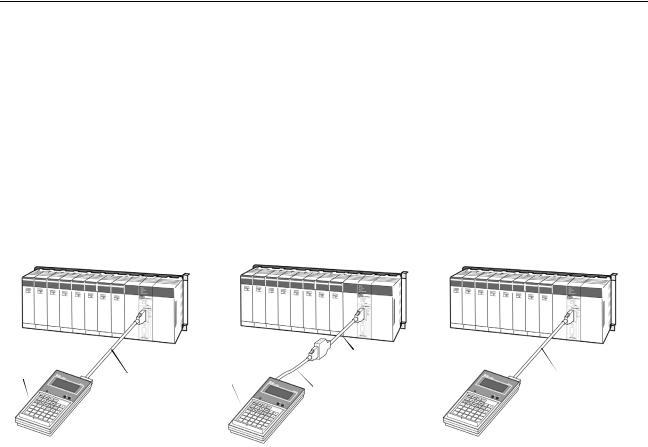
Applicable Programming Any of the following Programming Consoles can be used with CS/CJ-series Consoles PLCs: CQM1H-PRO01-E, CQM1-PRO01-E and the C200H-PRO27-E. The
Key Sheet and Connecting Cables listed below are required.
|
Programming |
Key Sheet |
Connecting Cables |
|
Console |
|
|
|
|
|
|
|
CQM1H-PRO01-E |
CS1W-KS001-E |
2-m cable included |
|
CQM1-PRO01-E |
|
CS1W-CN114 (0.05 m) |
|
|
|
|
|
C200H-PRO27-E |
|
CS1W-CN224 (2.0 m) or CS1W-CN624 |
|
|
|
(6.0 m) |
|
|
|
|
CS/CJ |
CS/CJ |
|
CS/CJ |
|
|
CS1W-KS001-E
Key Sheet
Connecting Cable provided with the CQM1H-PRO01-E
CQM1H-PRO01-E
CS1W-KS001-E
Key Sheet
CS1W-N114 Connecting Cable: 0.05 m
Connecting Cable provided with the CQM1H-PRO01-E
CQM1-PRO01-E
CS1W-KS001-E |
|
Key Sheet |
CS1W-CN224: 2.0 m |
|
|
|
CS1W-CN624: 6.0 m |
C200H-PRO27-E
The Programming Console is connected to the peripheral port on the CPU
Unit. It cannot be connected to the RS-232C port.
In a CS1D Duplex-CPU System, the Programming Console is connected to the active CPU Unit.
Applicable CPU Units
Series |
CPU Units |
Abbreviation in this manual |
|
|
|
CS Series |
CS1H-CPU6@-V1 |
CS1 CPU Unit |
|
CS1G-CPU4@-V1 |
|
|
CS1H-CPU6@H |
CS1-H CPU Unit |
|
CS1G-CPU4@H |
|
|
CS1D-CPU6@H |
CS1D CPU Unit |
|
CS1D-CPU@@S |
|
CJ Series |
CJ1G-CPU4@ |
CJ1 CPU Unit |
|
|
|
|
CJ1H-CPU6@H |
CJ1-H CPU Unit |
|
CJ1G-CPU4@H |
|
|
CJ1M-CPU@@ |
CJ1M CPU Unit |
2

Using the Programming Console |
Section 1-2 |
Operational Differences The operation of the Programming Console will vary with the CPU Unit that is for CPU Units connected as shown in the following table. These are the only differences in
Programming Console operation that vary with the CPU Unit.
Operation |
CS Series |
CJ Series |
||
|
|
|
|
|
|
CS1 |
CS1-H |
CJ1 |
CJ1-H |
|
CPU Units |
CPU Units |
CPU Units |
CPU Units |
|
|
|
|
|
Operating mode when at startup |
PROGRAM |
RUN |
|
|
(when PLC Setup is set to the |
|
|
|
|
default setting and the Program- |
|
|
|
|
ming Console is not connected) |
|
|
|
|
|
|
|
||
Selecting the display language |
Pin 3 on DIP |
Programming Console key switch |
||
|
switch on |
|
|
|
|
front panel |
|
|
|
|
of CPU Unit |
|
|
|
|
|
|
|
|
1-2 Using the Programming Console
Programming Console The Programming Console for CS/CJ-series PLCs is used to write, to make on-site adjustments to, and to protect user programs. To create and edit relatively large user programs, the CX-Programmer (running on a Windows computer) should be used.
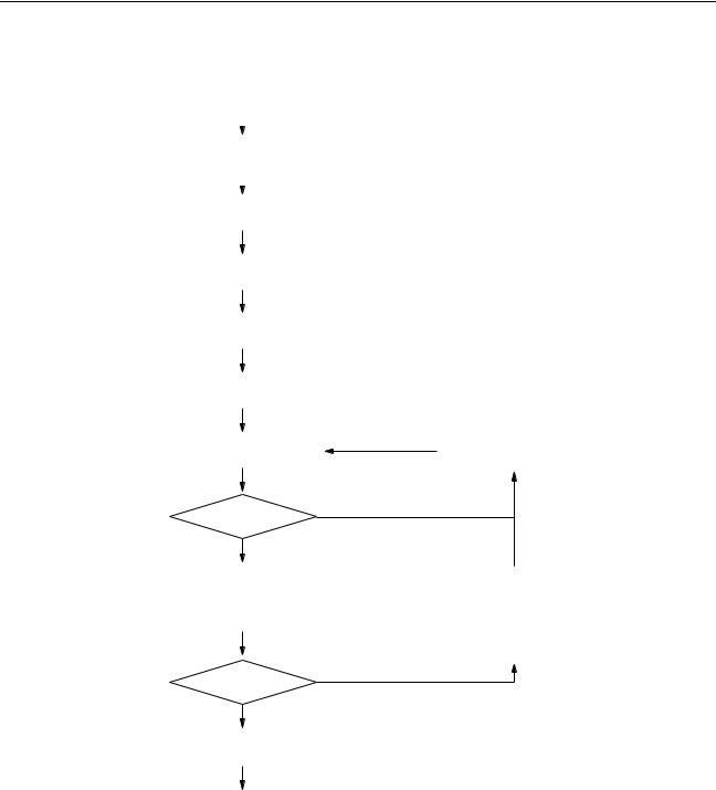
Programming Console Programming is started by using the CX-Programmer, a programming and Features monitoring software package that runs on a Windows computer, to create the program. Programming is completed by debugging the program on the PLC.
The Programming Console is used after programming has been completed to change the operating mode, change sections of the ladder program, monitor operation, change present values in I/O memory, change the PLC Setup, and read error information. The Programming Console can also be used to transfer and verify data between EM File Memory and the PLC.
3
Using the Programming Console |
|
|
|
|
|
|
|
|
Section 1-2 |
|||||||
One Cyclic Task |
|
|
|
More than One Cyclic Task |
|
|
|
|
|
|||||||
|
|
|
|
|
|
|
|
|
|
|
|
|
|
Indicates operations |
||
|
Programming |
|
|
|
Programming |
|
|
|
|
|||||||
|
|
|
|
|
|
|
|
which can be performed |
||||||||
|
|
|
|
|
|
|
|
|
|
|
|
|
|
from the Programming |
||
|
|
|
|
|
|
|
|
|
|
|
|
|
||||
|
|
|
|
|
|
|
|
|
|
|
|
|
|
Console |
||
|
|
|
|
|
|
|
|
|
|
|
|
|
|
|
||
|
|
|
|
|
|
|
|
|
|
|
|
|
|
|
|
|
|
|
|
Checking the program |
|
|
|
|
|
|
|
|
|
||||
|
|
|
|
|
|
|
|
|
First rack words cannot be set. |
|||||||
|
|
|
|
|
|
|
|
|
||||||||
|
|
|
|
|
|
|
|
|
||||||||
|
|
|
Creating I/O tables |
|
||||||||||||
|
|
|
|
|
|
|
|
|
|
|
|
|
|
|
|
|
|
|
|
|
|
|
|
|
|
|
|
|
|
|
|
|
|
|
|
|
|
PLC Setup |
|
|
|
|
|
|
|
|
|
|||
|
|
|
|
|
|
|
|
|
|
|
|
|
|
|
|
|
|
|
|
|
|
|
|
|
|
|
|
|
|
|
|
|
|
|
|
|
Setting DM allocations |
|
|
|
|
|
|
|
|
|
||||
|
|
|
|
|
|
|
|
|
|
|
|
|
|
|
|
|
|
|
|
|
|
|
|
|
|
|
|
|
|
|
|||
|
|
Transferring program to PLC |
|
|
|
|
|
|
|
|
|
|||||
|
|
|
|
|
|
|
|
|
|
|
|
|
|
|
|
|
|
|
|
|
|
|
|
|
|
|
|
|
|
|
|
|
|
|
|
|
|
Debugging |
|
|
|
|
|
Modifying the program |
|
|||||
|
|
|
|
|
|
|
|
|
|
|
|
|
|
|
|
|
|
|
|
|
|
|
|
|
|
|
|
|
|
|
Online Editing |
||
|
|
|
|
OK? |
No |
|
|
|
|
|
||||||
|
|
|
|
|
|
|
|
|
|
|
|
|
||||
|
|
|
|
|
|
|
Yes |
|
|
|
|
|
|
|
|
|
|
|
|
|
|
|
|
|
|
|
|
|
|
|
|
|
|
|
|
|
|
Trial operation |
|
|
|
|
|
Changing the set values |
|
|||||
|
|
|
|
|
|
|
|
|
for timers/counters |
|
||||||
|
|
|
|
|
|
|
|
|
|
|
|
|
|
|||
|
|
|
|
Monitoring |
|
|
|
|
|
Making changes to |
|
|||||
|
|
|
|
|
|
|
|
|
PLC Setup |
|
||||||
|
|
|
|
|
|
|
|
|
|
|
|
|
|
|||
|
|
|
|
|
|
|
|
|
|
|
|
|
Setting DM allocation |
|
|
|
|
|
|
|
OK? |
No |
|
|
|
|
|
||||||
|
|
|
|
|
|
|
|
|
||||||||
|
|
|
|
|
|
|
|
|
|
|
|
|
||||
|
|
|
|
|
|
|
Yes |
|
|
|
|
|
|
|
|
|
|
|
|
|
|
|
|
|
|
|
|
|
|
|
|
|
|
|
|
|
Actual operation |
|
|
|
|
|
Formatting Memory |
|
|
|||||
|
|
|
|
|
|
|
|
Cards/EM File Memory |
|
|
||||||
|
|
|
|
|
|
|
|
|
|
|
|
|
|
|
||
|
|
|
|
|
|
|
|
|
|
|
|
|
Transferring data between |
|
||
|
|
|
|
|
|
|
|
|
|
|
|
|
Memory Cards/EM files |
|
||
|
|
|
|
Monitoring |
|
|
|
|
|
and the PLC |
|
|||||
|
|
|
|
|
|
|
|
|
|
|
|
|
||||
|
|
|
|
|
|
|
|
|
|
|
|
|
||||
|
|
|
|
|
|
|
|
|
|
|
|
|
Verifying data between |
|
|
|
|
|
|
|
|
|
|
|
|
|
|
|
|
|
|
||
|
|
Reading error information |
|
|
|
|
|
Memory Cards/EM files |
|
|
||||||
|
|
|
on current errors |
|
|
|
|
|
and the PLC |
|
|
|||||
|
|
Note |
|
|
|
|
|
|
|
|
|
|
|
|||
|
|
The Programming Console cannot be used to create programs with more |
||||||||||||||
|
|
|
|
than one cyclic task. Use the CX-Programmer if more than one cyclic task is |
||||||||||||
|
|
|
|
required. |
|
|
|
|
|
|
|
|
|
|||
4
Loading...