


 Loading...
User Manual
3 MegaPixel CMOS Color Camera for Light Microscopy
SC30
Any copyrights relating to this manual shall belong to Olympus Soft Imaging Solutions GmbH. We at Olymnpus Soft Imaging Solutions GmbH have tried to make the information contained in this manual as accurate and reliable as possible. Nevertheless, Olympus Soft Imaging Solutions GmbH disclaims any warranty of any kind, whether expressed or implied, as to any matter whatsoever relating to this manual, including without limitation the merchantability or fitness for any particular purpose. Olympus Soft Imaging Solutions GmbH will from time to time revise the software described in this manual and reserves the right to make such changes without obligation to notify the purchaser. In no event shall Olympus Soft Imaging Solutions GmbH be liable for any indirect, special, incidental, or consequential damages arising out of purchase or use of this manual or the information contained herein.
No part of this document may be reproduced or transmitted in any form or by any means, electronic or mechanical, for any purpose, without the prior written permission of Olympus Soft Imaging Solutions GmbH.
Windows, Word, Excel and Access are trademarks of Microsoft Corporation which can be registered in various countries. Adobe and Acrobat are trademarks of Adobe Systems Incorporated which can be registered in various countries.
© Olympus Soft Imaging Solutions GmbH
All rights reserved
Printed in Germany
SC30_EN_07April2009
Olympus Soft Imaging Solutions GmbH, Johann-Krane-Weg 39, D-48149 Münster,
Tel. (+49)251/79800-0, Fax.: (+49)251/79800-6060

Contents
The SC30 Camera............................................................................ |
5 |
Image Acquisition Software getIT ................................................. |
7 |
Camera and light microscope........................................................ |
8 |
White Balance ................................................................................................ |
8 |
Monitor Settings for White Balance ..................................................... |
9 |
Executing White Balance ..................................................................... |
9 |
The (GUI) User Interface of getIT ................................................. |
10 |
Acquiring and saving images ..................................................... |
13 |
Set Input ............................................................................................ |
14 |
Acquire Image .................................................................................. |
16 |
Define calibration ............................................................................... |
20 |
Apply calibration ............................................................................... |
23 |
Save As ............................................................................................. |
24 |
Image Information ............................................................................. |
25 |
Additional commands................................................................... |
27 |
Open .................................................................................................. |
|
|
27 |
|
Print Directly |
...................................................................................... |
29 |
|
|
Print Setup... |
.....................................................................................30 |
3 |
||
Print... |
...............................................................................................31 |
|||
...............................................................................................File list |
|
|
32 |
|
Exit ..................................................................................................... |
|
|
33 |
|
Scale Bar, Show .............................................................in Viewport |
33 |
|
||
Scale Bar, Burn ................................................................into Image |
33 |
|
||
Delete Image ..................................................................................... |
|
34 |
|
|
Image Manager ................................................................................. |
34 |
|
||
Status Bar .......................................................................................... |
|
34 |
|
|
Standard Button ..........................................................................Bar |
35 |
|
||
About... |
.............................................................................................. |
|
35 |
|
Appendix I: |
|
Microscope settings ..................................................................... |
37 |
Illumination ................................................................................................... |
37 |
Objective, Total Magnification and Useful Magnification ............................. |
39 |
Appendix II: |
|
Installing the camera .................................................................... |
41 |
General Warnings ........................................................................................ |
41 |
Before the installation .................................................................................. |
42 |
USB 2.0 interface ......................................................................................... |
42 |
Installing the camera with Windows XP ....................................................... |
44 |
Installing the camera with Windows Vista .................................................... |
52 |

Contents
Appendix III: |
|
In case of problems with the camera........................................... |
59 |
Appendix IV: |
|
WEEE declaration.......................................................................... |
61 |
Appendix V: |
|
EMC declaration - SC30 ................................................................ |
62 |
Appendix VI: |
|
RoHS declaration - SC30 .............................................................. |
63 |
Index ............................................................................................... |
64 |
4 |

The SC30 Camera
The SC30 Camera
What is the SC30? The SC30 is a quick, high resolution CMOS color camera used for biomedical and material sciences applications. It was especially developed for acquisitions using light microscopy, has a special compact design, and can be connected to all types of light-microscopes via the C-mount.
Technical data |
|
SC30 |
|
|
|
Chip Type |
|
CMOS |
Chip Size |
Inch |
1/2 |
Effective Area, |
mm x mm |
6.55 x 4.92 |
(H) x (V) |
|
|
Pixel Size |
µm x µm |
3.2 x 3.2 |
Binning |
|
Color binning 2x, 3x, 4x |
Resolutions |
|
|
(H) x (V) |
|
|
at full resolution |
pixels |
2048 x 1532 |
Color binning 2x |
pixels |
1024 x 768 |
Color binning 3x |
pixels |
680 x 512 |
Color binning 4x |
pixels |
508 x 384 |
Frame Rate in the resp. |
|
|
resolutions 1) |
|
|
at full resolution |
fps |
10 |
Color binning 2x |
fps |
28 |
Color binning 3x |
fps |
37 |
Color binning 4x |
fps |
49 |
Analog to Digital Converter |
Bit |
10 |
Exposure times |
|
61 µs - 1745 ms |
PC-interface |
|
USB 2.0 |
Camera Mount |
|
Standard C-Mount |
1) Under the following conditions:
Pentium D 3 GHz Hyperthreading, 1 ms exposure time
5 |

The SC30 Camera
6 |
System |
To ensure that you can use your SC30 properly, the following system require- |
|
Requirements |
ments for your PC and your software need to be met: |
|
|
|
|
|
|
Hardware / Software |
|
|
|
|
Processor |
Intel® Pentium D better than, or equal to, 3.0 GHz |
|
|
Intel® Xeon (DP / MP) |
|
|
Intel® Core™Duo SSE2 compatible processor |
|
System memory capacity |
512 MB |
|
(RAM) |
|
|
Hard disk |
30 GB hard disk space |
|
Removable data media |
DVD-ROM |
|
Monitor |
1280 x 1024 resolution with 32-bit video card |
|
Interface |
USB 2.0 with Intel®82801DB/DBM USB2 ENHANCED |
|
|
HOST CONTROLLER |
|
Operating system |
Microsoft Windows® XP Professional (32 Bit) SP2 |
|
|
Microsoft Windows ® Vista (32 Bit) |
|
Internet browser |
Microsoft Internet Explorer 6.0 or higher |
A certain minimum amount of performance will be required of the PC you use to drive your camera if the speeds specified are to be reached in the live mode. The hardware recommendations are based on typical systems and processors. These recommendations can't include all of the systems, resp. hardware combinations, that are possible.
Image Acquisition Software getIT
Image Acquisition Software getIT
|
|
In addition to your camera, you have also received the image acquisition |
|
|
|
software getIT. The software offers the basic functions you need to acquire, |
|
|
|
view, calibrate, save, load, and print images. |
|
|
|
For more complicated tasks, you can connect your camera to a special software |
|
|
|
environment for image analysis and management. Olympus offers you a wide |
|
|
|
range of imaging system solutions which can be adapted to your individual |
|
|
|
needs in many different fields of application in the areas of sciences, industry, |
|
|
|
and medicine. They provide you with much more possibilities than getIT as they |
|
|
|
enable integrated acquisition, processing, visualization, and analysis of images, |
|
|
|
as well as device control, automatization, administration, networking, database |
|
|
|
archiving, and the results documentation. |
|
|
|
|
|
Warning |
|
Install the image acquisition software getIT before connecting your camera to |
|
|
|
||
|
|
your PC. This is necessary so that the operating system does not install the |
|
|
|
wrong TWAIN camera driver. The TWAIN camera driver which is necessary for |
|
|
|
|
|
|
|
using the camera is installed together with the software. See page 13 for more |
|
|
|
information about TWAIN. |
|
|
|
|
|
Installation of the software including the camera driver |
|
|
|
||
The following step-by-step instructions outline the principles of a generic instal- |
|
|
lation. You' ll find more detailed step-by-step instructions in the appendix (see |
7 |
|
page 41). They apply for any camera. |
||
1) |
Close any and all application programs. |
|
2) |
Place the installation CD into your computer's CD-ROM drive. |
|
|
" The setup program will start automatically - unless you have deacti- |
|
|
vated the autorun function. If so, start the setup.exe file via Windows |
|
|
Explorer with a doubleclick. |
|
3) |
An installation wizard guides you through the entire software installation. |
|
|
Simply follow the onscreen instructions and select the relevant entries. Se- |
|
|
lect the camera you wish to use. |
|
|
" The TWAIN camera driver which is necessary for using the camera is |
|
|
installed together with the software. |
|
4) |
After you have successfully installed your software, you may now connect |
|
|
your camera to your PC. |
|
|
" The camera driver is not signed and therefore not used automatically |
|
|
under your operating system. So you will have to register the camera |
|
|
driver with your operating system. |
|
5) |
Doubleclick the getIT program symbol to start the software. |
|
6) |
Within the image acquisition software click the Set Input button to check to |
|
|
see if the camera driver has been integrated successfully into the software. |
|
" Your camera driver has been integrated successfully if the camera is shown in the Set Input dialog box.
" If your camera does not appear in the Set Input dialog box, click the New Channel button. Select your camera from the Available devices list and click OK. Your camera driver should now be integrated successfully.

Camera and light microscope
7)Click the button with the cross located in the upper right corner of the Set Input dialog box to close it.
Camera and light microscope
Both the correct camera settings and the correct microscope settings are essential prerequisites for acquiring high quality images. The most important rules for the microscope settings are mentioned here; a more thorough explanation to the topic can be found in the appendix.
1)Use ND-filters to reduce the illumination intensity; do not alter the lamp voltage.
2)Establish Köhler illumination conditions.
3)Select the appropriate total magnification and the objective for the task in question.
White Balance
8 |
|
When using white balance, the individual color channels are scaled in a way that |
|
the white or neutral gray area of the image displayed on the monitor is displayed |
|
correctly as white or gray. The white balance can be carried out automatically on |
|
each image or manually for individual images. |
Mode of operation |
Select an area on the image that is uniformly gray or white. Such an area |
|
contains an equal intensity of the three color components: red, green and blue. |
|
White balance sets the color channels in such a way that this requirement is |
|
satisfied in the best possible way for the area selected. |
|
White balance is carried out on a part of the image (ROI). Your software alters |
|
the color settings in such a way that the image area in the ROI appears as white, |
|
resp. gray, as possible. After you have once carried out the white balance, you |
|
can reapply it any time, also to a running live-acquisition. |
Automatic White |
For the automatic white balance, a test image is acquired under optimal illumi- |
Balance |
nation conditions. The individual color channels are then set so that the acqui- |
|
sition also appears white or gray on the monitor. These channel settings are |
|
saved and used automatically for all additional acquisitions. |
Separate White |
You carry out a separate white balance on the current image. To do this, you |
Balance |
should select an area in the image which is, for the most part, gray or white. |
Microscope settings |
When you make an acquisitions prior to performing a white balance, your micro- |
|
scope's settings must be the same as those you use in normal practice. This |
|
especially holds true for the filter and the lamp voltage settings. The lamp voltage |
|
of a 12 V halogen lamp should be set to 9 V. It should, however, not be set lower |
|
than 5 V. Use the color neutral ND-filter, should you have to reduce light |
|
intensity. |
Related Topics
Appendix I: Microscope settings 37
|
Camera and light microscope |
|
|
Monitor Settings for White Balance |
|
Monitor Settings |
The monitor settings are decisive for the image you see on the monitor. Set your |
|
monitor to the appropriate color temperature, should your device allow this. To |
|
do this, compare the image's color impression on the monitor and in the |
|
eyepiece. |
Note |
The color temperature setting can be altered on most monitors via the monitor |
|
menu buttons located on the monitor. In other cases, the color temperature can |
|
be altered via the operating system. |
|
Changing the color temperature using the operating system |
|
|
|
1) |
Right click on Desktop. |
|
|
|
" The Desktop's context menu is opened. |
|
|
2) |
Select the entry Properties from the context menu. |
|
|
|
" The Display Properties dialog box is opened. |
|
|
3) |
Select the Settings tab. |
|
|
4) |
Click the Advanced button. |
|
|
|
" Another Display Properties dialog box is opened. The appearance and |
|
|
|
function of this dialog box depends on the graphics card installed on |
|
|
|
your system and your monitor. |
|
|
|
" Search for a tab with the name Color or Color Management. |
|
Note |
The appearance of the operating elements might differ from the one being |
9 |
|
|
described here because the adaptation of the color temperature is not part of the |
||
|
operating system, but rather is made accessible by the monitor manufacturer or |
|
|
|
the graphics card being used. |
|
|
|
5) |
Select a color temperature whose color impression best corresponds to that |
|
|
|
seen in the eyepiece. |
|
|
|
" Should your system offer a slide control with the options warm and cold, |
|
|
|
do not alter your color temperature with these. |
|
Executing White Balance
Specialized |
It may be difficult to execute a white balance in some microscopic methods, e.g. |
microscopy |
DIC or polarization. In these cases, execute the white balance using the bright |
techniques |
field method and only then change to the special methods. |
Transmitted Light |
When using the transmitted light method, look for a position through which the |
|
light passes through the cover slip, embedding material, and microscope slide, |
|
but not through the specimen. Should such a position not exist, remove the |
|
sample and carry out the white balance without a sample. |
Reflected light When using the reflected light method, you need a reference surface. Standardized gray cards are best for this. Should one not be available, you can also use white laboratory porcelain or neutral ND-filter paper. Should your samples contain very reflective areas, defocus your microscope when setting the white balance.
Related Topics
White Balance 17

The (GUI) User Interface of getIT
The (GUI) User Interface of getIT
10 |
GUI The graphical user interface influences the appearance of a program. It determines which menus there are, how the individual functions can be called up, how and where files, e.g., images, are displayed, and much more. This chapter describes the basic elements of GUI.
Button bars The most important commands are linked to a button providing you with quick and easy access to them.
Menu bar Some commands can be accessed through the corresponding menu.
Status bar The status bar contains the name of the camera and the current zoom factor of the active image.
Image buffer box Your software assigns an individual image buffer to each image. When you start up your image acquisition software all available image buffers will be empty. While working with the program, you fill each individual image buffer by loading or acquiring images. This means that many images are simultaneously accessible during any given work session. Only one image buffer however, may be active at a time.
You can hide the image buffer box to create more room for other windows, for example: use the [Alt + 2] shortcut.
Image window The image window is a special window which enables you to view all of your loaded images. It is possible to view up to 9 images simultaneously. To display Viewport them, the image window is divided up into several windows, i.e. viewports. Each
viewport can display a single image.
Images button bar The image window contains a button bar with which you can quickly alter the appearance of the images in the image window.
Zoom factor The zoom factor shows you by what percentage you have zoomed the image in or out.
•An automatic zoom factor is set by default. This means that the zoom factor is adapted to the current size of the Viewport. Alter the size of the window; in doing so, the image will be zoomed out so that it can always be viewed in its entirety. In doing so, the zoom factor will not be greater than 100%.
•You can enter a different zoom factor for each Viewport.
•The current zoom factor will be shown in the Viewport's header.
•When using a zoom factor of 100%, a pixel on the monitor corresponds exactly to one image pixel.
•A fixed zoom factor does not change when you change the size of the Viewport. Thus, in certain cases, only an image segment will be displayed in the Viewport.
•As soon as an image is larger than the Viewport, a slide control appears which enables you to move the image in the Viewport to and fro.
•Move the image directly via Pan&Scroll. Click into the image and keep the mouse button depressed. If the image is larger than the Viewport, the pointer changes its form. You now move the image by moving the mouse.

The (GUI) User Interface of getIT
11
The (GUI) User Interface of getIT
Optimizing display
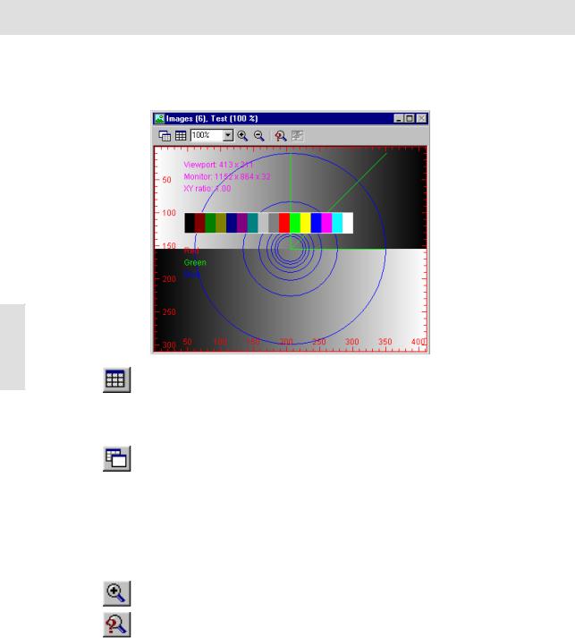
1)Use the [Ctrl + Alt + T] shortcut to create a test image.
"The image window contains a button bar with which you can quickly alter the appearance of the images in the image window.
Press [Ctrl + Alt + T] to generate a test image. Among other things, it shows you the current monitor resolution. Press [Ctrl + Alt + Shift + T] to
generate a color test image.
The test image is automatically the same size as the active viewport.
The test image will always be displayed at 100% zoom.
12 |
|
2) |
Click the Arrange Viewports button to redefine the number and arrange- |
|
ment of viewports. Select a 1x2 arrangement. |
|
" The image window will be divided up into two viewports. The test image |
|
is in the left viewport. Image buffers will be reassigned. Zoom factors will |
|
be set to Auto. Though reduced in size somewhat, the entire test image |
|
will be shown. |
3) |
Click the Single View button to display just one image in the image window |
|
- the active viewport image. |
|
" The viewport arrangement and what image buffers are shown in which |
|
viewports remain unchanged. |
|
" The Single View button changes to Tile View. |
4) |
Select one of the entries of the Zoom Factor dropdown list - or enter any |
|
zoom factor desired into the field directly; e.g., 30%. |
|
" The test image will be reduced to 30% zoom. The viewport will no longer |
|
be totally taken up by the image. Where the patterned background |
|
starts (in the viewport) is where the image stops. |
5) |
Click the Zoom In button to double the current zoom factor. |
|
" The test image will now be displayed at a zoom factor of 60%. |
6) |
Click the Adjust Zoom button to have the zoom factor adjusted to fit current |
|
viewport size. |
Acquiring and saving images
•The length/width ratio of the image will not change. Unlike the automatic zoom factor, the new zoom factor is not linked to the size of a window - i.e., even when you adjust the size of a window, the zoom factor stays the same. Automatic zoom factor is set by selecting the Auto entry from the Zoom Factor list.
7)Alter the size of the image window.
8)Click the Adjust Zoom to adjust the size of the window to the size of the current image (only available for single view).
Acquiring and saving images
This chapter describes how you can use your camera and software to acquire images and to save them to a storage medium. A step-by-step instruction briefly describes a typical sequence of steps. Afterwards, the commands used with all of the options will be described in more detail.
TWAIN The image acquisition is executed with your image acquisition software, via TWAIN. This abbreviation stands for "Technology Without An Interesting Name". TWAIN is a standardized software interface between software programs and image acquisition hardware such as digital cameras or scanners.
|
Your camera is controlled by a TWAIN driver. This allows you to make image |
|
acquisitions with other application programs which have access to a TWAIN |
|
interface. Examples for this are MS-Word and Adobe Photoshop. |
Note |
If you are using an imaging system solution provided by Olympus instead of the |
|
image acquisition software sent with your order, your camera will not require the |
|
TWAIN interface. Your camera will then be controlled directly by the correspond- |
|
ing software and entirely incorporated into the respective procedures. |
13 |
Acquiring, calibrating, and saving images
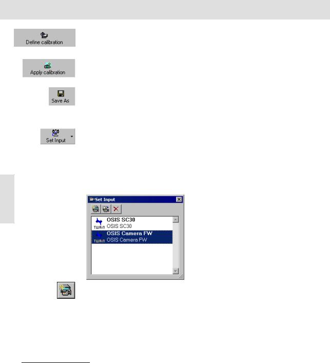
1)Click the Set Input button to select your camera.
"This step is only necessary if also a scanner is connected to your PC or if you manage several cameras with your image acquisition software and would like to choose another camera.
2)In the image buffer box, use your left mouse button to click the image buffer you would like to use to store your image.
"The selected image buffer will be highlighted in color. If it already contains an image, the next image buffer will be reserved for your image.
3)Click the Acquire Image button to open the TWAIN dialog box.
"The image will be shown live in the TWAIN dialog box.
"Use the live image to optimize the camera settings. Normally you only have to click the Auto button located in the Exposure time group. Sometimes also a white balance might be necessary.
"Click the Scan button to place the image into the selected image buffer, thus finalizing the actual image acquisition.
Related Topics
Acquire Image 16
Acquiring and saving images
4)Click the Define calibration button to determine the calibration data required for the X/Y calibration of your images.
"This step is only necessary if you would like to carry out a XY calibration of your images and the required calibration data is not yet available.
5)Click the Apply calibration button.
"This step is only necessary if you would like to calibrate the acquired image.
"You can always calibrate an image at a later time.
6)Click the Save As button to save the image as an image file to a storage medium.
Set Input
Click this button to select a camera. This is only necessary when several cameras are available and the wrong camera has been selected.
Your image acquisition software enables you to manage several cameras. Each camera is assigned to a predefined "logical input channel" within the software - if the camera driver has been correctly installed. If you want to acquire an image with a camera, the corresponding input channel must be activated.
14 |
Only one input channel can be activated. It will be highlighted in color in the dialog box's list and additionally displayed in the lower right part of the program window's status bar.
The Set Input command opens the dialog box with the with the same name.
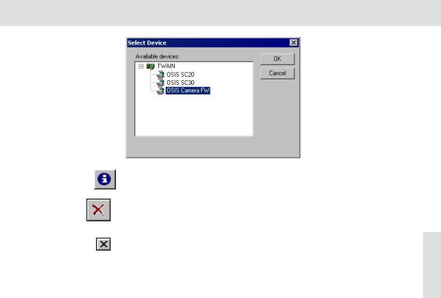
Click the New Channel button to create a new input channel for an additional camera.
Related Topics
Define calibration 20
Apply calibration 23
Save As 24
Acquiring and saving images
The New Channel command opens a dialog box in which all of the image sources, that can be currently selected by your image acquisition software, are listed. Select the desired image source. To display all image sources, click on the plus symbol.
Note |
You can also use the New Channel button, if you have deleted an input channel |
|
by mistake or if the camera driver has not been integrated successfully into the |
|
software. |
|
Click the Delete Channel, to delete a camera's input channel. You will receive a |
|
message if you really want to do this. If you select Yes, the input channel will be |
|
deleted and the corresponding entry from the Set Input dialog box's list will also |
|
be deleted. |
|
Click the button with the cross located in the upper right corner of the Set Input |
|
dialog box to close it. |
15 |
Acquiring and saving images
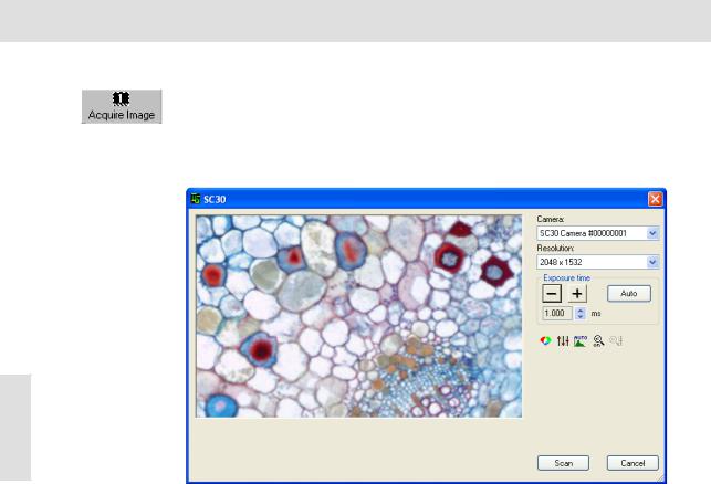
Acquire Image
Click this button to open the TWAIN dialog box for the image acquisition.
Before calling up the command, select the image buffer into which the image is to be stored. If it already contains an image, then the next image buffer will be reserved for the image.
Description of the TWAIN dialog box
This is what the TWAIN dialog box looks like for the SC30 camera.
16 |
Live image You will find your camera's live image in the left side of the TWAIN dialog box. The live image enables you to comfortably align, illuminate, and focus on the object, as well as the possibility to optimally set your camera's settings.
Camera
The Camera field shows you the selected cameras with their serial numbers.
Resolution
The Resolution list enables you to select which XY-resolution is to be used for acquiring the image. A lower resolution results from combining numerous neighboring pixels ("binning") or from partially reading out the pixels ("subsampling"). That depends on the camera type. The frame rate is increased both for binning and for subsampling. In addition the camera is more sensitive for binning. The SC30 type camera is able to use resolutions of 2048 x 1532, 1024 x 768, 680 x 512 and 508 x 384 pixels, for example.
Exposure time
You can set the exposure time in the Exposure time group.
Acquiring and saving images
Exposuretimeshorter
than 1 ms
Exposure time longer than 125 ms
The exposure time required for high-quality acquisitions depends on the illumination, the properties of the sample, and the camera being used. The exposure time should be longer than 1 ms and shorter than 125 ms. Should the exposure time be outside of these limits, you can take the following actions.
The best means of increasing the exposure time is by placing neutral density filters in your microscope's light path. If no neutral density filters are available, you should reduce your lamp voltage. But make sure that the voltage of a halogen lamp doesn't drop to below 5 V. When you have reduced your lamp voltage you will need to carry out a white balance again.
To reduce the exposure time, first remove any ND-filters that are in use. On the microscope, you can also additionally set the prism or the phototube's mirror to "only photo". Should the result still not be adequate, you can then increase the lamp voltage. After you have increased the lamp voltage, you should carry out another white balance.
Click the [-] and [+] buttons to change the exposure time in pseudo-logarithmic intervals. You can also click the arrow buttons next to the display field to alter the exposure time in linear intervals.
Click the Auto button to automatically set the exposure time.
White Balance |
|
Click the White Balance button to correct a tinge. During a white balance, the |
|
individual color channels for red, green, and blue are set in such a way, that a |
|
white or gray area of an object will be portrayed correctly in white, i.e., gray. All |
17 |
of the other colors will be shown correctly, as well. |
|
A red rectangle appears in the image. Move it with the mouse to a position as |
|
uniformly white or gray as possible. Change the size of the rectangle by moving |
|
the mouse and simultaneously depressing the mouse button. Rightclick to adopt |
|
position and size of the rectangle and execute the white balance. |
|
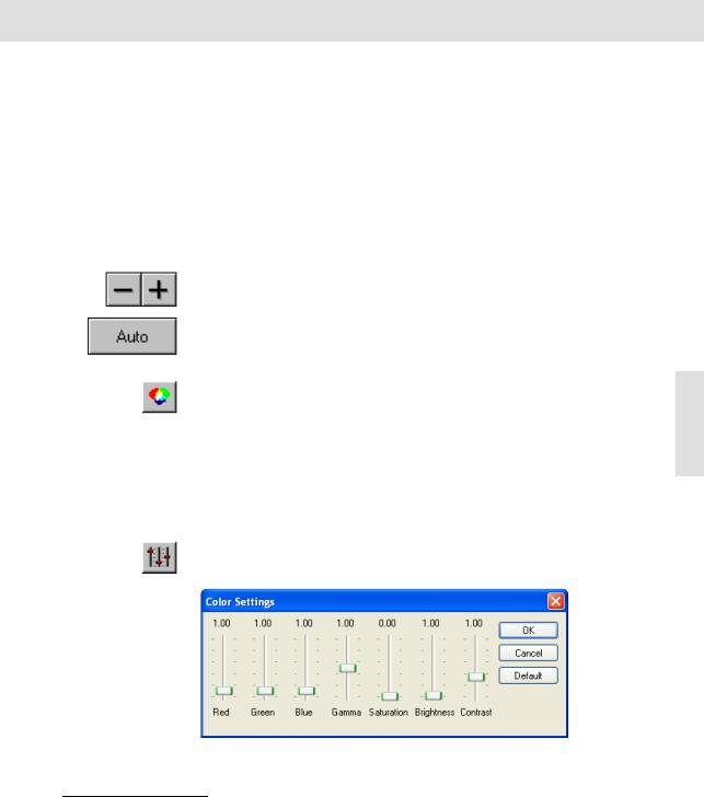
Color Settings
Click the Color Settings button to manually alter your camera's color settings. Based on the type of camera you are using, this may be done via numerous slide controls.
This is what the Color Settings dialog box looks like for the SC30 camera.
Related Topics
White Balance 8
Acquiring and saving images
18 |
Red, Green, Blue The Red, Green and Blue slide controls can be moved from 0,00 to 10,0. The set value is the factor with which the signals of the corresponding color channel are multiplied.
Gamma Use the Gamma slide control to result in a nonlinear contrast enhancement.
What is gamma? The numerical value of gamma influences how the illumination intensity on the CCD chip's pixels is converted into the color value of the respective pixels in the image buffer. Please note that this also applies for the other slide controls. If gamma equals 1, the conversion from illumination intensity into gray value i.e., color value is linear. A nonlinear contrast enhancement is the result if gamma is not equal to 1. If gamma is less than 1, the light gray values are spread more than the dark ones. This results in an improvement of contrast in the image's light areas. The image, in general, will become darker as a whole. If gamma is more than 1, the dark gray values are spread more than the light ones. This results in an improvement of contrast in the image's dark areas. The image, in general, will become lighter as a whole.
Saturation Use the Saturation slide control as an alternative to the slide controls of the individual color channels. The Saturation slide control enables you to alter the color reproduction from black and white to a maximum color saturation.
Brightness Use the Brightness slide control to change the image's intensity. Values smaller than 1 lower the image's intensity. Values greater than 1 increase the image's intensity.
Contrast Use the Contrast slide control to change the image's contrast. Values smaller than 1 lower the image's contrast. Values greater than 1 increase the image's contrast.
Default Click the Default button to set all of the slide controls to a predefined default value.
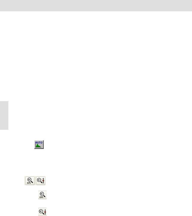
Auto Contrast
Click the Auto Contrast button, to activate or deactivate the automatic contrast enhancement. Now the image will always be shown with enhanced contrast onscreen no matter what the actual exposure conditions are, provided there is no over exposure. For this purpose, the system automatically calculates two sensible limits for displaying the intensity from the intensity distribution in the image. Intensity values below the minimal value and above the maximum values will be cut off. The intensity values in between will be spread out on the entire dynamic range of the camera.
|
Sharpen filter |
|
Use the sharpen filter to increase the sharpness using edge enhancement |
|
already with the live acquisition. |
Sharpen |
Click the Sharpen Filter On/Off button to activate/deactivate the sharpen filter. |
Filter On/Off |
The manner in which the acquired image is affected by the sharpen filter |
|
depends on the sharpen filter parameter. You can adjust this parameter by using |
|
the Sharpen Filter Settings dialog box. |
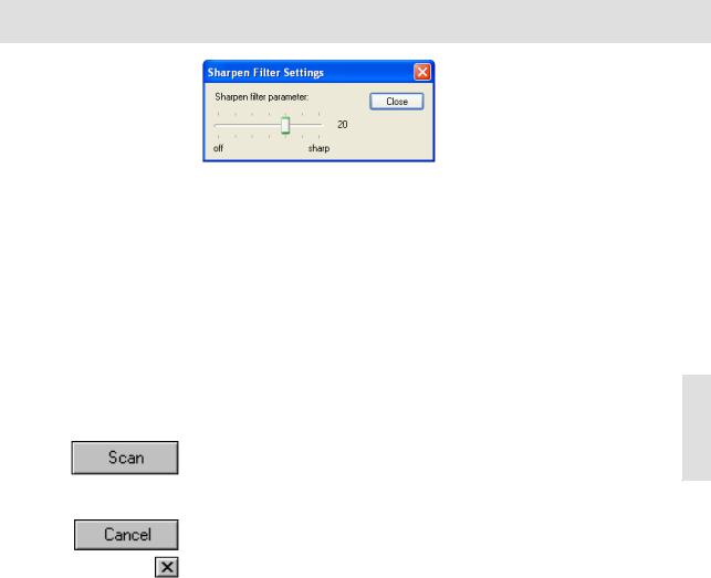
Sharpen |
Click on the Sharpen Filter Settings button to open a dialog box where you can |
Filter |
set the sharpen filter parameter: |
Settings |
|
Acquiring and saving images
To adjust the numerical value of the sharpen filter parameter, use the mouse to move the slide control to the right or left. Whether the contours of the image appear to be sharper or softer when you apply the sharpen filter, depends on the position of the Sharpen filter parameter slide control.
Increasing sharpness will accentuate edges, but also brings out more image noise. Reducing the sharpness makes the image softer. Entering a value of 0 will result in the sharpen filter having no effect at all.
Please note that when you use the sharpen filter you not only alter the monitor display, but the actual image information as well. This means that when you are planning on quantitatively evaluating your images later, you should not use the sharpen filter. Your software provides you with commands with which you can subsequently process an image's sharpness at any time.
The Sharpen Filter Settings button is only available if the sharpen filter has been |
|
|
activated. |
|
|
Scan |
19 |
|
Click the Scan button to place the image into the selected image buffer, thus |
||
|
||
finalizing your image acquisition. The TWAIN dialog box closes. You can now |
|
|
save the image as an image file. |
|
Cancel
Click the Cancel button to close the TWAIN dialog box, without acquiring an image. Only a black image will appear in the image buffer. As an alternative, you can cancel an image acquisition by clicking the button with the cross located at the upper right corner of the TWAIN dialog box.
Acquiring and saving images
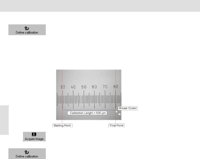
Define calibration
Click this button to determine the calibration data required for the X/Y calibration of your images. Such a calibration is only necessary and reasonable if you use your camera with a microscope or with a macro stand with one or more definite magnification ranges.
The image acquisition software enables you to calibrate images after acquisition. Calibration means that for each magnification the width and height of an object area is assigned to the pixel representing that object area. This might be, for example, 0,63 µm x 0,63 µm for a magnification of 5x. This calibration data varies for each magnification.
1) Place a stage micrometer under your microscope and focus.
The illustration shows a light microscope's micrometer.
20 |
2)Click the Acquire Image button to acquire an image of the stage micrometer.
"The image will be put into the active image buffer.
3)Click the Define calibration button to open the dialog box required to determine the calibration data.
4)Click the Calibrate... button.
"The Calibrate Image dialog box opens.
Loading...