


ASSEMBLY/SETUP
MANUAL
MX61/MX61L
200mm/300mm COMPATIBLE SEMICONDUCTOR/FPD INSPECTION MICROSCOPES
This manual is for assembly and setup of the Olympus MX61/MX61L Semiconductor/FPD Inspection Microscopes. To ensure the safety, obtain optimum performance and familiarize yourself fully with the use of this microscope, we recommend that you study this manual thoroughly before operating the microscope. As this manual will be needed when you replace the lamp or fuses or modify a setup, retain it in an easily accessible place near the work desk for future reference.
A X 7 5 9 9

MX61/MX61L
CONTENTS
IMPORTANT – Be sure to read this section for safe use of the equipment. – 1-7
1 NOMENCLATURE
2ASSEMBLY
8-10
11-24
2-1 |
Assembly Diagram ............................................................................................................................... |
............................................ 11 |
2-2 |
Detailed Assembly Procedures ........................................................................................................................... |
12-22 |
2-3 |
Modules Installed by Olympus............................................................................................................................ |
23-24 |
1 Transmitted Light Module (MX-TILLA/TILLB)
2 (Optional) Light Path Setup
3 Reflected Neutral Density Filter (ND 0.5)
3 CENTRATION OF THE MERCURY/XENON BURNER
4MICROSCOPE CONTROL FROM COMPUTER
25-26
27-37
1 |
RS-232C Communication Parameters |
2 |
Connection of the RS-232C Cable |
3 |
Connection of Connectors and Pin Assign |
|
|
4 |
Communication Specifications |
|
|
5 |
Command List |
6 |
Command Details |
7 |
Error Code List |
|
|
5 |
EXTERNAL CONTROL OF REVOLVING NOSEPIECE |
38 |
||||
|
|
|
|
|
|
|
|
1 |
Connector Used |
2 Pin Layout and Signal Names |
|
||
|
3 |
Control Specifications |
|
|
||
|
4 |
Revolving Nosepiece Position Numbers (Index Nos. on the Center of Revolving Nosepiece) |
||||
|
|
|
|
|
|
|
6 |
MAINTENANCE PART LISTS |
|
39 |
|||
|
|
|
|
|
||
|
|
|
PROPER SELECTION OF THE POWER SUPPLY CORD |
40-41 |
||
|
|
|
||||

IMPORTANT
These microscopes employ a UIS2 (UIS) (Universal Infinity System) optical design, and should be used only with UIS2 (UIS) eyepieces, objectives, observation tubes, etc. Less-than-optimal performance may result if inappropriate accessories are used.
The MX61L microscope is compatible with a stage stroke of 300 mm (12 inches) and the MX61 microscope is compatible with that of 200 mm (8 inches).
SAFETY PRECAUTIONS
1.Always use the power cord provided by Olympus. If no power cord is provided, please select the power cord by referring to the section “PROPER SELECTION OF THE POWER SUPPLY CORD” at the end of this instruction manual. If the proper power cord is not used, Olympus can no longer warrant the electrical safety performance of the equipment. Lay out the power cord at a sufficient distance from the sources of heat such as the power supply unit/light source and lamp housing to avoid contact with these heat sources.
2.To avoid potential shock hazard, always set the main switch @ to (OFF)
(OFF)
and disconnect the power cord before replacing the burner or connecting/ disconnecting motorized parts. And since the system contains motorized parts, do not plug in the power cord until all of the assembly procedures have completed.
|
}Always use the lamp bulb or burner supplied by Olympus. |
||
@ |
Bulb/Burner |
Model |
Average Life |
Halogen bulb |
· 12V100WHAL-L (Long life type) |
|
|
|
2000 hrs. |
||
|
|
(PHILIPS 7724) |
|
|
|
|
|
Fig. 1 |
|
· 12V100HAL (High-resolution type) |
50 hrs. |
|
|
(PHILIPS 7023) |
|
|
|
|
|
|
Mercury burner |
· USH-103OL |
300 hrs. |
|
|
(USHIO) |
|
|
|
|
|
|
|
· HBO103W/2 |
300 hrs. |
|
|
(OSRAM) |
|
|
|
|
|
|
Xenon burner |
· UXL-75XB-A |
200 hrs. |
|
|
(USHIO) |
|
|
|
|
|
|
Halogen bulb for |
· JCR12V-100WB |
|
|
light guide light |
(USHIO) |
1000 hrs. |
|
source |
|
|
3.Do not light the mercury or xenon burner while it is not mounted on the microscope because the UV rays in their light are harmful to your eyes. The used mercury burner should be disposed of as an industrial waste. If you cannot dispose of it properly, contact Olympus.
4.The eye point of this microscope can be adjusted in the range between 408 and 560 mm above the desktop surface. Prepare a microscope desk with an optimum height for the application of the customer.
1

MX61/MX61L
5.The desktop surface on which the microscope system is installed should be almost horizontal with a tilting angle of less than 20’ with the MX61L or less than 1° with the MX61 (to prevent spontaneous displacement of the stage) and rigid. (The weight of the microscope system with standard module combination is about 53 kg, or 116.6 lbs, with the MX61L and about 44 kg, or 96.8 lbs, with the MX61.)
}Although these microscopes are designed with excellent vibration resistance, their maximum performance can be achieved when an anti-vibration bench is used.)
6.The lamp housing surface at the rear of the microscope frame will become very hot during operation. When installing the microscope, ensure that there are ample free spaces (of more than 100 mm) around and in particular above and below the lamp housing. Also, the power cord and other cables should be laid out at distances from the microscope because contact with them may result in their fusion and an electric shock due to it.
7.To avoid a potential shock hazard, make sure that the power cord is safety grounded/earthed.
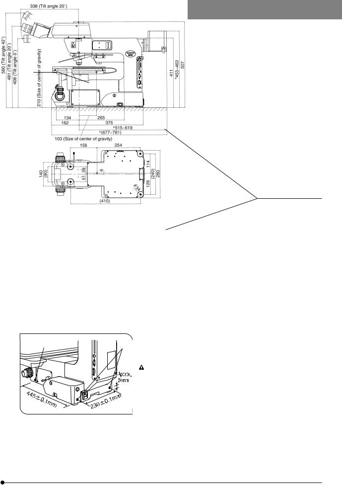
8.To allow each microscope manifest its full performance, reserve an installation space having the minimum dimensions
described below before assembly and installation of the microscope. (Sizes in |
|
) |
}The dimensions of the area enclosed in alternate long and two short dashes lines indicate the stage movement range. The dimensions marked * are variable depending on the lamp housing used.
}When maintenance is required, a larger work space can be prepared by changing the observation tube orientation or moving the stage.
}The following installation space is set according to the SEMI standard guidelines (SEMI S8-1103). It is recommended that you set the optimum installation space for each customer by referring to the following installation space data as well as the appearance of the system, eye point height, etc.
MX61L installation space
Unit: mm
MX61L
Stage movement range
Installation space
2

MX61 installation space
MX61
Stage movement range
MX61L external view, eye point and center of gravity
Eye point
(Bottom view of microscope)
Unit: mm
Installation space
Unit: mm
Position of center of gravity
(Note) The center of gravity is an approximate position when the microscope is equipped with the standard module combination for transmitted light observation. Note that the position is variable depending on the weight of
specimen, position of the stage and other modules used.
3
MX61/MX61L
MX61 external view, eye point and center of gravity
Unit: mm
Eye point
Position of center of gravity
(Bottom view of microscope)
(Note) The center of gravity is an approximate position when the microscope is equipped with the standard module combination for transmitted light observation. Note that the position is variable depending on the weight of specimen, position of the stage and other modules used.
9.To prevent toppling of the microscope system, keep the total height of the microscope below 1 meter (3.3 ft) when attachments (including Olympus optional modules and the CCD camera prepared by the customer) are mounted.
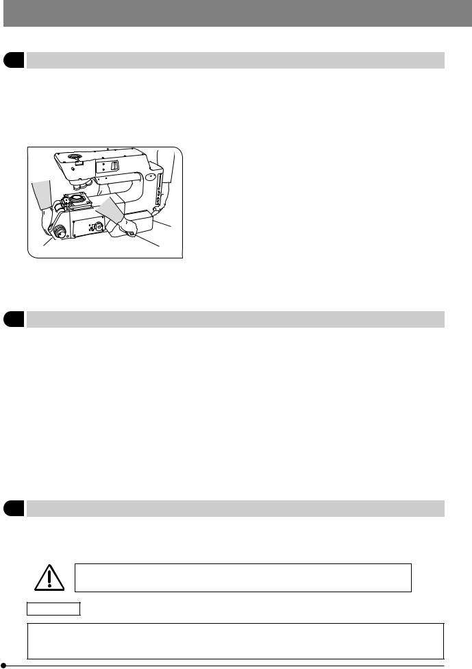
10. Each microscope has screw holes (M5, depth 10 mm) for prevention of
@ |
² |
toppling (in the case of an earthquake or microscope imbalance) on the |
|
|
|
|
|
side panels @ (x 2 holes) and the rear panel ² (x 2 holes). Clamp the |
|
|
microscope using L-shaped clamps and these screw holes as required. |
|
|
When clamping the microscope using L-shaped clamps pre- |
|
|
pared by the customer, be sure to use steel bolts (strength cat- |
|
|
egory 12.9) with as long as possible threaded sections (8 mm |
|
|
or more is recommended). |
|
Fig. 2 |
|
4
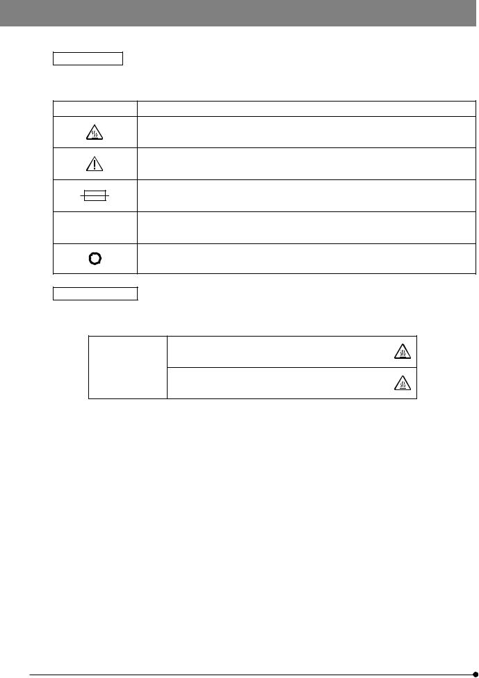
Safety Symbols
The following symbols are found on the microscopes. Study the meaning of the symbols and always use the equipment in the safest possible manner.
Symbol |
Explanation |
|
|
Indicates that the surface becomes hot, and should not be touched with bare hands.
Before use, carefully read the instruction manual. Improper handling could result in injury to the user and/or damage to the equipment.
Indicates a potential fire hazard; when replacing fuses, be sure replacement fuses are of the specified rating.
lIndicates that the main switch is ON.
Indicates that the main switch is OFF.
Caution indications
Caution indications are affixed at parts where special precaution is required when handling and using the microscope. Always heed the cautions.
|
Lamp housing/power supply |
[High temperature caution] |
|
unit |
|
Caution indication |
|
|
positions |
Light guide light source |
|
|
[High temperature caution] |
|
|
(LG-PS2) |
|
|
|
5
MX61/MX61L
1Getting Ready
1.Do not use the microscope where it is subjected to direct sunlight, high temperature and humidity, dust or vibrations. (For the operating conditions, refer to chapter 8, “SPECIFICATIONS “ in the Instruction Manual.)
2.A microscope is a precision instrument. Handle it with care and avoid subjecting it to sudden or severe impacts. Never attempt to rotate the motorized revolving nosepiece by hand; otherwise, the gear or other parts may be damaged.
3.When moving the microscope, detach the observation tube, stage, lamp housing and specimen to reduce the total system weight, and then
|
|
insert the two provided carrying rods @ firmly into the left and right side |
|
|
panels. Two persons are needed to carry the microscope; one should |
|
|
hold the front holding section ² and a carrying rod and the other person |
|
|
should hold the rear holding section ³ and the other carrying rod. Be |
|
|
sure to move the microscope cautiously. (The microscope frame weight |
|
|
is about 30 kg, or 66 lbs.) |
|
|
³ }After movement, remove the carrying rods, and either have the customer |
² |
@ |
retain them without losing or attach them to the two screw holes on the |
rear of the microscope. Attach the provided screw hole caps to the screw |
||
Fig. 3 |
|
holes left by removing the carrying rods. |
|
#Do not change the position of the microscope by sliding it on the |
|
|
|
desktop surface; otherwise, the rubber feet will be damaged. |
4.Be sure to attach the transport clamping plate(s) to the stage before transporting it.
2Maintenance and Storage
1.To clean the lenses and other glass components, simply blow dirty away using a commercially available blower and wipe gently using a piece of cleaning paper (or clean gauze).
If a lens is stained with fingerprints or oil smudges, wipe it gauze slightly moistened with commercially available absolute
alcohol.
 Since the absolute alcohol is highly flammable, it must be handled carefully.
Be sure to keep it away from open flames or potential sources of electrical sparks –– for example, electrical equipment that is being switched on or off. Also remember to always use it only in a well-ventilated room.
2.If any part of the equipment (other than glass components) gets dirty, with it with a clean cloth.
If the party is extremely dirty, do not attempt to use organic solvents to clean it; instead, use a soft, lint-free cloth slightly moistened with a diluted neutral detergent.
3.Never disassemble any part other than instructed of the microscope. This could result in malfunctions or reduced performance.
4.When not using the microscope, keep it covered with a dust cover. Make sure the lamp housing is cool before covering the microscope.
5.When disposing of the microscope. Check the regulations and rules of your local government and be sure to observe them.
3Applicable Standards
1.These devices are in compliance with or certified by the following standards.
2.Although these devices are designed for use in industrial environments, their full performances may not be manifested if they are not operated properly. Be sure to handle them properly as instructed in this manual.
These devices are designed for use in industrial environments (Class A devices).
Using them in a residential environment may affect other equipment in the environment.
CE marking
This device complies with the requirements of both directive 89/336/EEC concerning electromagnetic compatibility and directive 73/23/EEC concerning low voltage. The CE marking indicates compliance with the above directives.
6

FCC
These devices have been subjected to the compliance evaluation of the following FCC regulation: · FCC Part 15, Subpart B: Radio Frequency Equipment (Commercial and industrial areas)
NOTE: This equipment has been tested and found to comply with the limits for a Class A digital device,
pursuant to Part 15 of the FCC Rules. These limits are designed to provide reasonable protection
against harmful interference when the equipment is operated in a commercial environment. This
equipment generates, uses, and can radiate radio frequency energy and, if not installed and used in
accordance with the instruction manual, may cause harmful interference to radio communications.
Operation of this equipment in a residential area is likely to cause harmful interference in which case
the user will be required to correct the interference at his own expense.
FCC WARNING: Changes or modifications not expressly approved by the party responsible for compliance
could void the user’s authority to operate the equipment.
SEMI
These devices have been subjected to the compliance evaluations of the following guidelines under the S8 Standard.
·S2-0703: Safety Guidelines for Semiconductor Manufacturing Equipment
·S8-1103: Safety Guidelines for Ergonomics Engineering of Semiconductor Manufacturing Equipment
4Caution
If the microscope is used in a manner not specified by this manual, the safety of the user may be imperiled. In addition, the equipment may also be damaged. Always use the equipment as outlined in this manual.
The following symbols are used to set off text in this instruction manual.
!: Indicates that failure to follow the instructions in the warning could result in bodily harm to the user and/or damage to equipment (including objects in the vicinity of the equipment).
# : Indicates that failure to follow the instructions could result in damage to equipment. } : Indicates commentary (for ease of operation and maintenance).
7

MX61/MX61L
NOMENCLATURE
}The illustration shows the MX61L.
}The modules shown below are examples of those used in a typical system. Certain modules are usable even when they are not mentioned below. For these modules, refer to the latest catalogues or contact Olympus.
For the modules marked *, refer to their instruction manuals.
|
|
Observation Tube |
|
|
Motorized Revolving Nosepiece |
MX61L |
|
|
U-D5BDREMC |
||
Eyepieces |
MX-SWETTR (FN 26.5) |
||
U-D6REMC |
MX61 |
||
|
|||
SWH Series |
U-P5REMC |
||
MX-SWETTR (FN 26.5) |
|||
(FN 26.5) |
|
||
|
U-SWTR-3 (FN 26.5) |
||
WHN/WH Series |
|
||
|
U-TR30-2 (FN 22) |
||
(FN 22) |
|
||
|
U-BI30-2 (FN 22) |
||
|
|
Objectives
MPLFLN/
MPLFLN-BD
LMPLFLN/
LMPLFLN-BD
MPLN/
MPLN-BD
UMPlanFl/
UMPlanFl-BD Series
LMPlanFl/
LMPlanFl-BD Series
MPlanApo/
MPlanApo-BD Series
LMPlanApo/
LMPlanApo-BD Series
MPlan/MPlan-BD Series
Stage |
|
|
MX61L |
|
|
MX-SIC1412R2 (Transmitted light/ |
|
|
reflected light observation model) |
|
|
MX61 |
|
|
MX-SIC8R (Transmitted light/ |
|
|
reflected light observation model) |
|
|
MX-SIC6R2 |
|
|
(Reflected light observation only) |
|
|
MX-SIC6A |
Transmitted Light Module |
|
(Reflected light observation model) |
||
|
||
|
MX-TILLA |
|
|
MX-TILLB |
Microscope Frame
Flexible Light Guide
MX61L-F
LG-SF *
MX61-F
Lamp Housing
U-LH100-3/LH100L-3 (Halogen bulb) U-LH100HG/LH100HGAPO (Mercury burner)
U-LH75XEAPO (Xenon burner) (Note) The MX-HGAD adapter is
required for the mercury burner and xenon burner.
Intermediate Attachment (Only one of the following can be attached.)
U-EPA2 *
U-CA/ECA *
MX-AFSU *
U-CFU *
Breath Shield
MX-BSH
MX-BSH-ESD
Light Source
LG-PS2 *
Hand Switch
U-HSTR2
8
Stage and Holder System for the MX61
Rotary Wafer Holder BH2-WHR43 (For 3-4 inch wafers) BH2-WHR54 (For 4-5 inch wafers)
BH2-WHR65 (For 5-6 inch wafers) Rotary Wafer Holder Plate MX-WHPR86 (For 6-8 inch wafers)
5-Inch Mask Holder
BH3-MH5
Rotary Wafer Holder Plate
BH3-WHP6
4-Inch Mask Holder
BH3-MH4
Black Plate
BH3-SP6
Glass Plate
BH3-SPG6
6x6-Inch Stage
MX-SIC6A
6x6-Inch Stage
MX-SIC6R2
8x8-Inch Stage
MX-SIC8R
9
MX61/MX61L
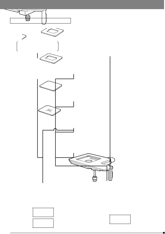
Stage and Holder System for the MX61L
6-Inch Mask Holder |
Glass Plate |
Rotary Wafer Holder for 8-inch |
||||
and 12-inch wafers |
||||||
MX-MH6 |
MX-SPG1412 |
|||||
MX-WHPR128 |
||||||
|
|
|
|
|||
|
|
|
|
|
|
|
|
|
|
|
|
|
|
|
|
|
|
|
|
|
14x12-Inch Stage
MX-SIC1412R2
10

ASSEMBLY
2-1 Assembly Diagram |
|
|
|
||
}The diagram below shows where the various modules should be |
|
Tools Used |
|||
mounted. Study the assembly instructions for only the modules to be |
(Provided with the microscope frame) |
||||
employed. |
|
|
|
Allen screwdriver (3 mm) |
|
#When assembling the equipment, make sure that all parts are free |
|
||||
|
|
||||
of dust and dirt and avoid scratching any parts or touching glass |
|
Allen wrench (3 mm) |
|||
surfaces. |
|
|
|
||
|
|
|
|
||
|
|
TV system |
Observation tube |
|
Tool holder |
|
|
Photomicrographic |
MX61L |
|
|
|
|
|
|
||
|
|
system |
MX-SWETTR |
|
|
|
|
|
|
|
|
|
|
|
MX61 |
|
|
|
Eyepieces |
|
MX-SWETTR |
|
|
|
SWH Series |
|
U-SWTR-3 |
Halogen bulb |
100 W halogen |
|
WHN Series |
|
U-TR30-2 |
lamp housing |
|
|
|
12V100WHAL-L |
|||
|
|
|
U-BI30-2 |
U-LH100-3 |
|
|
|
|
12V100WHAL |
||
|
|
|
|
U-LH100L-3 |
|
|
|
|
Intermediate attachment |
||
|
|
|
|
||
|
Motorized revolving |
|
(Only one of the following |
|
|
|
nosepiece |
|
can be attached.) |
|
|
|
U-D5BDREMC |
|
U-EPA2 |
|
High-intensity |
DIC slider |
U-D6REMC |
|
U-CA/ECA |
|
lamp housing |
U-P5REMC |
|
MX-AFSU |
|
U-LH75XEAPO |
|
U-DICR |
|
|
U-CFU |
|
U-LH100HG |
U-DICRH |
|
|
|
|
U-LH100HGAPO |
U-DICRHC |
|
|
|
Adapter |
|
|
|
|
|
|
|
|
|
|
|
MX-HGAD |
|
Breath shield |
|
|
Power cord |
||
|
|
|
|
||
MX-BSH |
|
|
|
Note 2) |
|
MX-BSH-ESD |
|
|
AF connector |
|
|
|
|
|
Light guide |
Light source |
|
|
|
Microscope frame |
LG-PS2 |
||
|
Brightfield |
LG-SF |
|
||
|
MX-61L-F |
Filters |
|
||
|
|
|
|||
|
objective |
MX61-F |
|
|
|
|
|
U-25ND6-2 |
|
||
|
adapter |
|
|
|
|
|
(Transmitted light |
|
U-25ND25-2 |
|
|
|
BD-M-AD |
|
|
||
|
module) |
|
U-25LBD |
|
|
|
|
|
|
||
Brightfield/ |
Brightfield |
MX-TILLA |
|
U-25IF550, etc. |
|
MX-TILLB |
|
|
|
||
darkfield |
objective |
|
|
|
|
|
|
|
|
||
objective |
|
|
Analyzer |
|
|
|
|
|
Hand switch Note 1) |
||
|
Holders |
|
U-AN360-3 |
||
|
|
U-HSTR2 |
|||
(See pages 9 and 10.) |
|
|
|||
|
|
|
|
||
|
|
|
Polarizer |
|
|
|
|
|
U-PO3 |
|
|
Stage
MX61L
MX-SIC1412R2
MX61
MX-SIC8R
MX-SIC6R2
MX-SIC6A
11
Note 1) Exclusive connector for the U-HSTR2 hand switch. To prevent malfunction, do not connect other modules.
Note 2) Exclusive connector for the MX-AFCB control box for use with an Olympus active AF unit. To prevent malfunction, do not connect other modules.
}The tools used can be stored in the holes on the tool holder provided with the microscope frame. Use the double-sided adhesive tape of the tool holder to attach it to a position that does not hinder operation.
!Do not attach the tool holder anywhere near the bottom of the lamp housing since it generates high-temperature heat.

MX61/MX61L
2-2 Detailed Assembly Procedures
!The system contains motorized parts. Do not plug in the power cord until all of the assembly procedures have completed.
1 |
Attaching the Stage |
(Figs. 4 & 5) |
²
Fig. 4
³
@ |
| |
Fig. 5
ƒ
1.Using the Allen wrench (3 mm), remove the transport clamping plate @ from the rear edge of the stage. (Fig. 5) The removed screws should be used to clamp the stage when attaching it.
}With the MX-SIC6R2/SIC6A, the mounting screw holes are invisible unless the upper stage is displaced. It is therefore necessary to remove the transport clamping plates from the front and rear of the stage.
#Two transport protection sheets are placed in the gaps of the MXSIC6A/SIC6R2/SIC8R stage. Be sure to remove them before using the system.
2.While holding the stage so that the coarse adjustment grip and X-axis/ Y-axis knobs are on the right, gently place the stage on the stage holder ². Using the Allen screwdriver or Allen wrench, tighten the four screws temporarily.
3.Remove the transport clamping plate(s) from the front ³ and side (MXSIC1412R2 only) | of the stage, move it to the rearmost position and,
after confirming that the stage and arm do not interfere with each other, tighten the four screws firmly. (Fig. 5)
#The clutch and belt may stick together and prevent smooth operation of the release function if the stage has not been moved for a long time. If this phenomenon occurs, take the remedial action described in page 22 in the instruction manual.
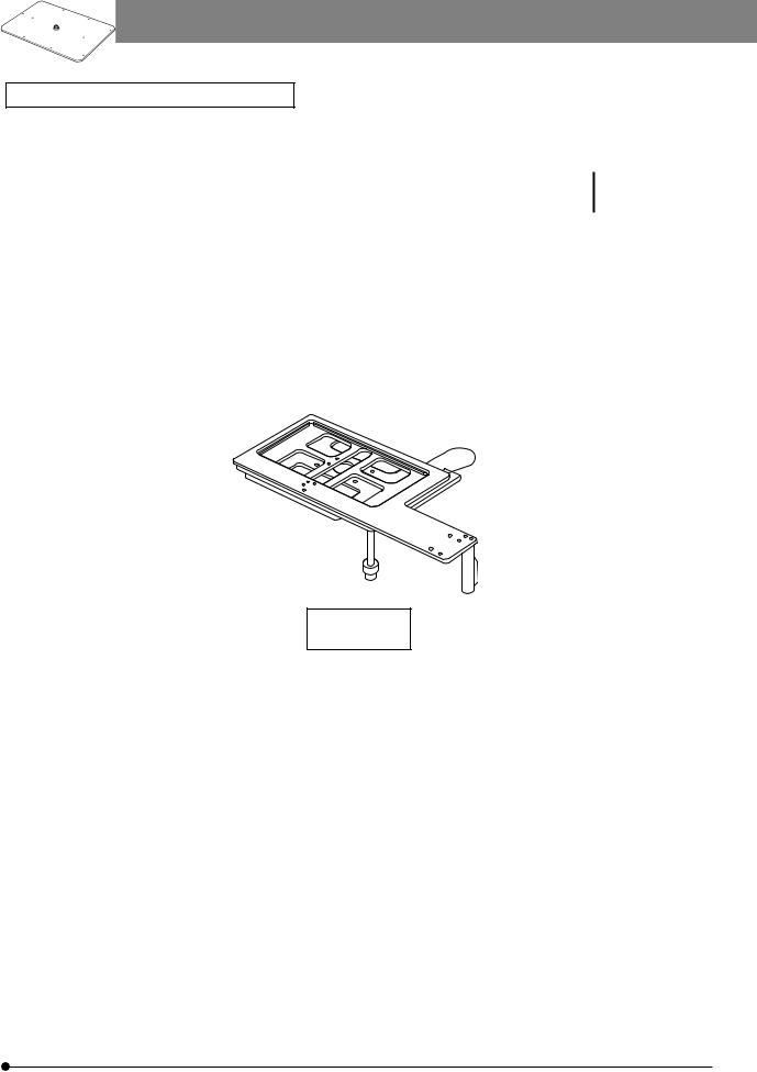
Attaching the Y-Stroke Limit Stopper (Fig. 6)
}When the MX-SIC1412R2 stage is used in transmitted light observation (possible only when the MX-TILLA is used), it is required to attach this stopper for limiting the Y-axis stroke to 10 inches in order to prevent interference between the stage and the projected part of the condenser.
1.Place the stage upside down and remove both transport clamping plates.
2.Move the stage and insert the stopper, provided with the stage, into the two stopper holes ƒ on the center stage.
3.Attach only the front transport clamping plate and then attach the stage.
Fig. 6 |
Caution Before Transporting the Stage (Fig. 5) |
Before transporting the stage, be sure to attach the transport clamping plates @³| and package the stage carefully. Do not transport the stage when it is attached to the microscope frame or inadequately packaged. Otherwise, the stage will be damaged.
12
 Loading...