


Main modules described in this manual
MVX10
MVX-2RE MVX-CA2X SZX-STAD1 SZH-STAD1 SZX-STAD2 SZ2-FO SZH-SG SZH-SC
INSTRUCTIONS
MVX10
RESEARCH MACRO ZOOM
SYSTEM MICROSCOPE
This instruction manual is for the Olympus MVX Research Macro Zoom System Microscope. To ensure the safety, obtain optimum performance and familiarize yourself fully with the use of this attachment, we recommend you study this manual thoroughly before operating the microscope. Retain this instruction manual in an easily accessible place near the work desk for future reference.
A X 7 4 4 1

This device complies with the requirements of directive 98/79/EC concerning in vitro diagnostic medical devices. CE marking means the conformity to the directive.

MVX10
CONTENTS
Correct assembly and adjustments are indispensable for the microscope to manifest its full performance. If you want to assemble the microscope by yourself, refer to Chapter 11, “ASSEMBLY” before other chapters. (P. 36 to P. 44)
IMPORTANT — Be sure to read this section for safe use of the equipment. — 1-4
1 NOMENCLATURE
2CONTROLS
3 SUMMARY OF REFLECTED FLUORESCENT LIGHT OBSERVATION PROCEDURE
4OPERATION
5
6, 7
8, 9
10-17
|
4-1 |
Base ....................................................................................................................................................................................................................... |
|
|
10 |
|
|
|
1 |
Using the Stage Plate |
2 |
Placing the Specimen |
|
|
4-2 |
Microscope Body and Focusing Assembly........................................................................................ |
10, 11 |
|||
|
|
1 |
Adjusting the Focus |
|
|
|
|
|
2 Adjusting the Rotation Tension of the Coarse Focus Adjustment Knob |
|
|||
|
|
3 |
Engaging and Disengaging the Zooming Knob Click Stop Position |
|
||
|
|
4 |
Adjusting the Aperture Iris Diaphragm |
5 |
Using the Objective Correction Collar |
|
|
4-3 |
Coaxial Fluorescence Illuminator....................................................................................................................... |
|
|
12-15 |
|
|
|
1 |
Selecting the Fluorescence Mirror Unit |
2 |
Turning the Burner ON |
|
|
|
3 |
Opening/Closing the Shutter |
4 |
Using the Field Iris Diaphragm |
|
|
|
5 |
Switching the Filter Slider Knob |
|
|
|
|
4-4 |
Observation Tube ...................................................................................................................................................................... |
|
|
15-17 |
|
|
|
1 |
Adjusting the Tilt |
2 |
Adjusting the Interpupillar Distance |
|
|
|
3 |
Adjusting the Diopter (Zoom Parfocality Adjustment) |
|
||
|
|
4 |
Using the Eye Shades |
5 |
Using the Eyepiece Micrometer Disk |
|
|
|
6 |
Selecting the Light Path |
7 |
Switching the Monaural/Stereo View |
|
|
|
|
||||
5 |
TV OBSERVATION AND PHOTOMICROGRAPHY |
18, 19 |
||||
|
|
|
|
|
|
|
1 Selecting the C-Mount Adapter Magnification
2 Attaching the C-Mount Adapter 3 Selecting the TV Camera Light Path 4 Adjusting the Parfocality Between Observation Image and Monitor Image

6 TRANSMITTED LIGHT OBSERVATION
7TROUBLESHOOTING GUIDE
8SPECIFICATIONS
9OPTICAL CHARACTERISTICS
10 OPERATION OF OTHER MODULES
20
21
22
23
24-35
10-1 |
Revolving Nosepiece MVX-2RE ..................................................................................................................... |
24, 25 |
10-2 |
Magnification Changer MVX-CA2X ....................................................................................................................... |
26 |
10-3 |
BX Stage Adapter Type 1 SZX-STAD1 .................................................................................................... |
27-29 |
10-4 |
Stage Adapter Type 1 SZH-STAD1......................................................................................................................... |
29 |
10-5 |
BX Stage Adapter Type 2 SZX-STAD2 .................................................................................................. |
30, 31 |
10-6 |
Vertical-Movement Stage SZ2-FO ................................................................................................................ |
31-33 |
10-7 |
Gliding Stage SZH-SG ................................................................................................................................................. |
33, 34 |
10-8 |
Cup Stage SZH-SC ........................................................................................................................................................... |
34, 35 |
11 ASSEMBLY |
36-45 |
|||
|
|
|
|
|
11-1 |
Assembly Diagram........................................................................................................................................................................ |
36 |
||
11-2 |
Detailed Assembly Procedures ........................................................................................................................ |
37-43 |
||
11-3 |
Centration of the Mercury (Xenon) Burner and Field Iris Diaphragm ...... |
44, 45 |
||
|
|
PROPER SELECTION OF THE POWER SUPPLY CORD |
46, 47 |
|
|
|
|||

MVX10
IMPORTANT
 SAFETY PRECAUTIONS
1.After observation of a specimen that involves the risk of infection, be sure to clean the positions that contacted the specimen to prevent infection.
·To avoid the risk that the specimen drops and splatters, be sure to remove the specimen before moving the microscope.
·If a specimen is destroyed due to an erroneous operation, immediately take the infection prevention measures.
·The microscope becomes unstable when its height is increased by a mounted attachment. To prevent the specimen from dropping if the microscope topples down, be sure to take the toppling prevention measures when mounting an attachment.
2.The applicable ultrahigh-pressure mercury burners are the USH-103OL (OLYMPUS) and HBO103W/2 (OSRAM), both of which are DC mercury burners available from Olympus.
3.Ensure that the burners are mounted and that the cords are connected securely.
4.The inside of the lam housing is very hot while the burner is on and immediately after it is turned off. Do not open the lamp housing in these periods (see page 42).
5.The power supply unit contains high-voltage parts inside. Do not attempt to disassemble it.
6.Always use the power cord provided by Olympus. If no power cord is provided, please select the power cord by referring to the section “PROPER SELECTION OF THE POWER SUPPLY CORD” at the end of this instruction manual. If the proper
power cord is not used, Olympus can no longer warrant the electrical safety performance of the equipment.
Before plugging the power cord into the wall outlet, ensure that the main switch of the power supply unit is set to “ ” (OFF).
7.Always ensure that the grounding terminal of the power supply unit is properly grounded. If the equipment is not grounded, Olympus can no longer warrant the electrical safety performance of the equipment.
8.Before opening the lamp housing for replacing the burner, be sure to set the main switch to “ ” (OFF), unplug the lamp housing output connector of the power supply unit and wait at least 10 minutes or until the burner and lamp housing
have cooled down.
9.The top of the lamp housing becomes very hot. To avoid the risk of a fire, never block the ventilation of this part. Make sure you leave a space of 10 cm or more around the lamp housing and power supply unit to dissipate heat.
10.The power cord is also used to shut off the power supply unit in case of emergency by unplugging. To facilitate this, locate the power supply unit or wall outlet so that the power cord connector (on the rear of the power supply unit) or the wall outlet is easily accessible in case of emergency.
Safety Symbols
The following symbols are found on the microscope. Study the meaning of the symbols and always use the equipment in the safest possible manner.
Symbol |
Explanation |
|
|
Indicates the presence of a high voltage (1 kV or more), which should not be touched to prevent an electric shock.
Indicates that the surface becomes hot, and should not be touched with bare hands.
Before use, carefully read the instruction manual. Improper handling could result in injury to the user and/or damage to the equipment.
lIndicates that the main switch is ON.
Indicates that the main switch is OFF.
1
Caution indications
Caution indications are affixed at parts where special precaution is required when handling and using the microscope. Always heed the cautions.
|
· Lamp housing |
[High temperature caution] |
|||
Caution indication |
(U-LH100HG, U-LH10HGAPO) |
||||
|
|
|
|||
positions |
· Power supply unit |
[High voltage caution] |
|||
|
|||||
|
|
|
|
|
|
1Getting Ready
}This instruction manual pertains only to the operating procedures of the Research Macro Zoom System. Also read the instruction manuals for the modules used in combination with the microscope system so that you can understand the comprehensive operating procedures of the system.
1.A microscope is a precision instrument. Handle it with care and avoid subjecting it to sudden or severe impact. Also be careful in handling the limiting or stopper mechanisms because an excessive force may destroy them.
2.Do not use the microscope where it is subjected to direct sunlight, high temperature and humidity, or vibration.(For the operating environment, see Section 8, “SPECIFICATIONS” on page 22.)
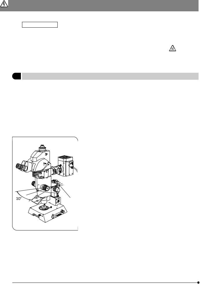
3.To prevent the microscope body from turning over, its pivot angle must be limited to 30° and the tilt angle of the desk surface must
be limited to 5° as shown in Fig.1.
4. Care is required when using an auxiliary pillar (SZH-P400/P600) because it increases the height of the microscope body and makes it unstable.
5. To adjust the microscope body height, be sure to hold the focusing assembly with one hand and then loosen the focusing assembly clamping knob @. (Fig. 1)
(Use the drop prevention collar (SZX-R) to prevent a hazard from occurring.)
Be careful not to pinch your finger during adjustment.
@
Fig. 1
2

MVX10
6.Observe the following cautions when operating the coarse focus adjustment knobs or the zooming knobs.
³ 
|
@ |
² |
| |
|
Fig. 2
Operation |
Manipulated |
|
Caution |
|
Controls |
|
|
Focusing |
Coarse focus |
1. |
If the knob hits the upper or lower lim- |
|
adjustment |
|
iting mechanism violently or it is rotated |
|
knobs @ (Fig. 2) |
|
after it hits a limiting mechanism, the |
|
|
|
internal mechanism may be damaged. |
|
|
|
|
|
|
2. |
If the knobs on the left and right are |
|
|
|
rotated in opposite directions, the in- |
|
|
|
ternal mechanism will be damaged. |
|
|
|
(The rotation tension of the knob |
|
|
|
should be adjusted using the rotation |
|
|
|
tension adjustment ring ³ on the |
|
|
|
knob. See page 10.) |
|
|
|
|
Zooming |
Zooming knobs |
1. |
If the knob hits the upper or lower lim- |
|
² (Fig. 2) |
|
iting mechanism violently or it is rotated |
|
|
|
after it has hit a limiting mechanism, |
|
|
|
the internal mechanism may be dam- |
|
|
|
aged. |
|
|
|
|
|
|
2. |
If the knobs on the left and right are |
|
|
|
rotated in opposite directions, the inter- |
|
|
|
nal mechanism will be damaged. |
|
|
|
|
7.Before moving the microscope, detach the modules including the tilting trinocular head and lamp housing to reduce the total weight. Then hold it by the base, not by the zoom microscope body.
2Maintenance and Storage
1.To clean the lenses and other glass components, simply blow dirty away using a commercially available blower and wipe gently using a piece of cleaning paper (or clean Gauze).
If a lens is strained with fingerprints or oil smudges, wipe it gauze slightly moistened with commercially available absolute alcohol.
 Since the absolute alcohol is highly flammable, it must be handled carefully.
Be sure to keep it away from open flames or potential sources of electrical sparks - for example, eletrical equipment that is being switched on or off.
Also remember to always use it only in a well-ventilated room.
2.The equipment uses plastic resins extensively in its external finish. Do not attempt to use organic solvents to clean the non-optical components of the microscope. To clean these components, use a lint-free, soft cloth lightly moistened with a diluted neutral detergent.
3.Never disassemble any part of the microscope as this could result in malfunctions or reduced performance.
4.When not using the microscope, keep it covered with the dust cover provided. Ensure that the lamp housing is cool before covering the microscope.
5.When the hour counter on the power supply unit indicates 300 hours (USH-103OL, HBO103W/2), set the main switch to “ ” (OFF) for safety, wait for more than 10 minutes and then replace the burner (see page 42). Unlike the fluorescent lamps, the mercury burner seals high-pressure gas inside. If it used after the specified service life has been exceeded,
the glass tube may be distorted accumulatively and may eventually burst, though this happens very rarely. The used mercury burner should be disposed of as an industrial waste. If you cannot dispose of it properly, contact Olympus.
6.When disposing of the microscope. Check the regulations and rules of your local government and be sure to observe them. To dispose of only the gas spring (|, Fig. 2) used in the counterbalance of the focusing assembly, follow the precautions provided with the gas spring.
3

3Caution
If the microscope is used in a manner not specified by this manual, the safety of the user may be imperiled. In addition, the microscope may also be damaged. Always use the microscope as outlined in this instruction manual.
The following symbols are used to set off text in this instruction manual.
 : Indicates that failure to follow the instructions in the warning could result in bodily harm to the user and/or damage to equipment (including objects in the vicinity of the equipment).
# : Indicates that failure to follow the instructions could result in damage to equipment. } : Indicates commentary (for ease of operation and maintenance).
4

1 |
MVX10 |
NOMENCLATURE |
}The module names listed below are typical ones that can be used with the system, and the illustration shows the system composed of modules marked {. Certain other modules are also usable even when they are not mentioned below. For these modules, refer to the latest catalogues or contact Olympus.
For the modules marked *, refer to their instruction manuals.
Observation Tube
{ Tilting Trinocular Head: MVX-TTRS
· Tube Lens Unit: MVX-TLU
Eyepieces
{ WHN10X-H
Coaxial Fluorescence Illuminator
{ MVX-RFA
<<Fluorescence mirror units >>
·U-MCFPHQ/XL
·U-MGFPHQ/XL
· U-MYFPHQ/XL · U-MRFPHQ/XL · U-MGFP/XL
· U-MGFPA/XL
Zoom Microscope Body
{ MVX-ZB10
Revolving Nosepiece
· MVX-2RE
Objective Lens
{ MVPLAPO 1X
·MVPLAPO 0.63X
·MVPLAPO 2XC
Stage Glass & base accessories
{ Stage Glass: SP-C
·Fluorescence Center Plate: SP-FL
·Stage Plate (B&W): SP-BW-2
·Base accessories
C-Mount Adapter
{ MVX-TV 1XC
· MVX-TV 0.63XC
High-Intensity Lamp Housing
{ U-LH100HG (for mercury burner)
·U-LH100HGAPO (for mercury burner)
·U-LH75XEAPO* (for xenon burner)
ND Filter
· 32ND6 · 32ND12 · 32ND25 · 32ND50
Magnification Changer
· MVX-CA2X
Focusing Assembly
{ MVX-FOF
Base
{ Transmitted Illumination Base : SZX-ILLB2*
·Transmitted Illumination Base : SZX-ILLD2*
·Transmitted Illumination Base : SZX-ILLK*
· Large Base |
: SZX-STL |
5

CONTROLS
}If the microscope is not yet assembled, go to Chapter 11, “ASSEMBLY” (pages 36 to 45).
The following illustration shows the systems with the modules enclosed in 
 . For other ancillary modules, see subsequent pages.
Tilting Trinocular Head |
|
C-Mount Adapter |
MVX-TTRS |
|
MVX-TV 1XC |
|
|
|
Coaxial Fluorescence Illuminator
MVX-RFA
Diopter adjustment ring (P. 16)
Eyepiece clamping knobs
Mirror unit turret (P. 12)
Mirror unit indicator pocket (P. 38)
Zooming knob (P. 16)
Aperture iris diaphragm knob (P. 11)
Zoom ratio indicator (P. 11)
UV shield plate
Zoom Body
MVX-ZB10
MVX objective
Light path selector lever (P. 17)
C-mount (P. 18)
Mono/stereo selector lever (P. 17)
Lamp Housing for Mercury Burner
U-LH100HG/U-LH100HGAPO
Burner centering knobs (P. 44)
Collector lens focusing knob (P. 44)
Filter slider knob (P. 15)
Field iris diaphragm lever (P. 14)
Coarse focus adjustment knob (P. 10)
Fine focus adjustment knob (P. 10)
Coarse focus adjustment knob rotation tension adjustment ring (P. 10)
Shutter knob (P. 14)
Transmitted Illumination Base
SZX-ILLB2
(Refer to the separate instruction manual.)
Focusing Assembly
MVX-FOF
6
MVX10
Fluorescence mirror units U-MCFPHQ/XL U-MGFPHQ/XL U-MYFPHQ/XL U-MRFPHQ/XL U-MGFP/XL U-MGFPA/XL
}Up to three fluorescence mirror units can be mounted by placing them in every other dovetail of the six dovetails of the MVX-RFA.
#Each fluorescence mirror unit is composed of the dichroic mirror, barrier filter and excitation filter that match a specific fluorescent protein.
}When fabricating an original fluorescence unit by your own, it is recommended to use the U-MF/XL mirror unit frame (which does not incorporate a filter). (P. 39)
Use the blank indicator sheets provided with the illuminator to write the original mirror unit name.
Power Supply Unit
}For details, see the instruction manual provided with the U-RFL-T.
U-RFL-T
Hour counter
Lamp ON LED
Main switch
I : ON
 : OFF
: OFF
Xenon Lamp Housing
U-LH75XEAPO
Power Supply Unit
U-RX-T
}For details, see the instruction manual provided with the U-LH75XEAPO and U-RX-T.
Lamp housing connector
Power cord connector
Tube Lens Unit MVX-TLU
C-mount adapter mount dovetail
 Mount dovetail
7

SUMMARY OF REFLECTED FLUORESCENT LIGHT OBSERVATION PROCEDURE
}For the observation procedures of other methods, see page 20.
3-1 Preparation
1. |
Set the shutter knob to “{” to close the shutter. |
(Page 14) |
2. |
Mount the fluorescence mirror unit(s) that match the desired observation. |
(Page 38) |
3. |
Turn the mirror unit turret to engage the desired fluorescence mirror units in the light path. |
(Page 12) |
4. |
Turn on the mercury burner and wait until the arc stabilizes (for about 5 to 10 minutes). |
|
|
(If the burner is not centered, center it.) |
(Page 14) |
3-2 Observation Procedure
|
|
|
|
|
(Controls) |
(Page) |
|
|
|
|
|
|
(P. 10) |
||
Place the specimen on the base. |
|
|
|||||
|
|
|
|
|
|
|
|
|
|
|
|
|
|
|
|
Engage the optimum mirror unit for the speci- |
|
@ Mirror unit turret |
(P. 12) |
||||
men in the light path. |
|
||||||
|
|
|
|||||
|
|
|
|
|
|
|
|
|
|
|
|
|
|
||
Set the shutter knob to “¦” to open the shut- |
² Shutter knob |
(P. 14) |
|||||
ter, and bring the specimen into focus. |
³ Coarse/fine focus adjustment knobs |
(P. 10) |
|||||
|
|
|
Engage the ND filter in the light |
| ND filter |
(P. 15) |
||
|
|
|
|||||
|
|
|
path as required. |
||||
|
|
|
|
|
|||
|
|
|
|
|
|
||
Adjust the field of view so that it is uniform |
ƒ Collector lens focusing knob |
(P. 44) |
|||||
and brightest. |
|||||||
|
|
||||||
|
|
|
Adjust the tilt. |
… Binocular assembly |
(P. 15) |
||
|
|
|
|||||
|
|
|
Adjust the interpupillar distance. |
… Binocular assembly |
(P. 16) |
||
|
|
|
|||||
|
|
|
Adjust the diopter. |
† Diopter adjustment ring |
(P. 16) |
||
|
|
|
|
|
|
||
Open the field iris diaphragm and adjust the |
‡ Field iris diaphragm lever |
(P. 14) |
|||||
aperture iris diaphragm. |
Š Aperture iris diaphragm knob |
(P. 11) |
|||||
|
|
|
|||||
|
|
|
|
|
|||
Set the zooming knob for the desired zoom ratio |
‰ Zooming knob |
(P. 16) |
|||||
and bring the specimen into focus. |
³ Coarse/fine focus adjustment knobs |
(P. 10) |
|||||
|
|
|
|||||
|
|
|
|
||||
START OF OBSERVATION |
|
|
|||||
}To interrupt observation for a short period, close the shutter. |
² Shutter knob |
(P. 14) |
|||||
8

MVX10
… |
ƒ |
|
†
|
‡
@
³
²
Š |
‰ |
}Make a photocopy of this spread and post it near the microscope for quick reference.
9

OPERATION
4-1 Base
1Using the Stage Plate
1.When performing reflected light observation, place the stage plate with the white or black side up according to the specimen.
2.When performing transmitted light observation, use the transparent stage glass.
2Placing the Specimen
Place the specimen on the approximate center of the stage plate (or stage glass). Hold the specimen with the specimen holder as required.
4-2 Microscope Body and Focusing Assembly
| @
@
²
 ³
³ 
Fig. 3
1 |
Adjusting the Focus |
(Fig. 3) |
|
|
With both the coarse focus adjustment knob @ and fine focus adjust- |
||
|
ment knob ², rotating the knob in the direction of the arrow lowers the |
||
|
microscope body. |
|
|
|
· Stroke per turn of the coarse focus adjustment knob: 36. 8mm. |
||
|
· Stroke per turn of the fine focus adjustment knob |
: 1.5 mm. |
|
|
|
|
|
2 |
Adjusting the Rotation Tension of the |
(Fig. 3) |
|
Coarse Focus Adjustment Knob |
|||
|
|||
#The rotation tension of the coarse focus adjustment knob can be adjusted with the rotation tension adjustment ring ³. Do not rotate the knobs on the left and right in opposite directions, for this will damage the internal mechanism.
}This adjustment is intended to facilitate the rotation of the knob while preventing the microscope body from lowering spontaneously. For best ease of use, it is recommended to adjust the rotation tension slightly tighter than the level at which spontaneous lowering of the microscope body occurs.
1. Rotate the rotation tension adjustment ring ³ by inserting the Allen screwdriver into the hole | on the ring periphery.
Rotating the ring clockwise increases the rotation tension of the coarse focus adjustment knob, and rotating counterclockwise decreases it.
#If the microscope body falls down by its own weight or the focus obtained by fine focusing is lost immediately, the rotation tension adjustment may be too light. In this case, rotate the ring clockwise to increase the rotation tension.
#If the rotation tension adjustment is too tight, delicate focusing will be impossible and the knob may be damaged. Particularly, never rotate the fine focus adjustment knob quickly while its rotation tension is extremely tight.
10

MVX10
|
|
|
|
|
|
|
|
3 |
Engaging and Disengaging the |
(Fig. 4) |
|
Zooming Knob Click Stop Position |
|
||
|
|
@
Fig. 4
@
Fig. 5
}When the click stop knob is engaged to ON, the click stop function is engaged for each zoom ratio indicated with the zooming knob. When the knob is disengaged to OFF, the zoom magnification can be varied continuously and finely near the click groove.
}Click stop can be provided for the nine zoom ratios from 0.8 to 5. The click stop is engaged when the microscope leaves the factory.
1.To disengage the click stop function, rotate the click stop ON-OFF screw @ counterclockwise (by about two turns from the ON position, in the direction opposite to the arrow) using the Allen screwdriver.
#Do not rotate too much, or the cover may be damaged.
2.To engage the click stop function, rotate the click stop ON-OFF screw @ fully clockwise (in the direction of the arrow) using the Allen screwdriver.
The zooming knob then stops at every position corresponding to the zoom ratio indicated on the zoom ratio indicator ².
²
4 |
Adjusting the Aperture Iris Diaphragm |
(Fig. 5) |
}Adjusting the aperture iris diaphragm improves the insufficiency of brightness in the peripheral section light at intermediate zoom ratios as well as the depth of focus.
However, setting the aperture iris diaphragm too narrowly degrades resolution.
When performing fluorescent light observation, it is recommended to open the aperture iris diaphragm fully for bright observation.
1. Adjust the aperture iris diaphragm knob @ to the left or right.
Rotating the ring toward the left “¦” opens the aperture; rotating it toward the right “  ” closes it.. Adjust while monitoring the observed image to confirm the contrast and focal depth improvement effects.
#Do not close the aperture too much, for this may cause degradation in resolution and/or insufficiency of brightness in the peripheral section.
@
Water depth 5 mm or less
Fig. 6
5 |
Using the Objective Correction Collar |
(Fig. 6) |
}The MVPLAPO 2XC objective is equipped with a correction collar @, which corrects the aberration produced by a medium such as water or plastic container.
When observing the specimen through a liquid or petri dish cover, rotate the correction collar to find the position that provides the best contrast,
·Correction is possible for aberrations equivalent to a water depth of about 5 mm.
·The effect of the correction collar may be less sensible when the zoom ratio is low or the aperture iris diaphragm is stopped down.
}When the MVX-2RE revolving nosepiece is used, hold the objective so that the revolving nosepiece does not displace from the position when
turning the correction collar @.
11
4-3 Coaxial Fluorescence Illuminator
1Selecting the Fluorescence Mirror Unit
}Use the fluorescence mirror unit that is optimum for each purpose of observation.
Mirror unit name |
Dichroic mirror |
Excitation filter |
Barrier filter |
|
Application |
|
U-MCFPHQ/XL |
DM450HQ |
BP425-445HQ |
BA460-510HQ |
|
ECFP |
|
|
|
|
|
|
|
|
U-MGFPHQ/XL |
DM485HQ |
BP460-480HQ |
BA495-540HQ |
|
EGFP |
|
|
|
|
|
|
|
|
U-MYFPHQ/XL |
DM505HQ |
BP490-500HQ |
BA515-560HQ |
|
EYFP |
|
|
|
|
|
|
|
|
U-MRFPHQ/XL |
DM565HQ |
BP530-555HQ |
BA570-625HQ |
|
RFP |
|
|
|
|
|
|
|
|
U-MGFP/XL |
DM505 |
BP460-490 |
BA510IF |
|
EGFP |
|
U-MGFPA/XL: |
|
|||||
|
|
|
|
|||
U-MGFPA/XL |
BA510-550 |
|
|
|||
|
|
|
For dye separation |
|
||
|
|
|
|
|
|
|
|
|
|
|
|
|
|
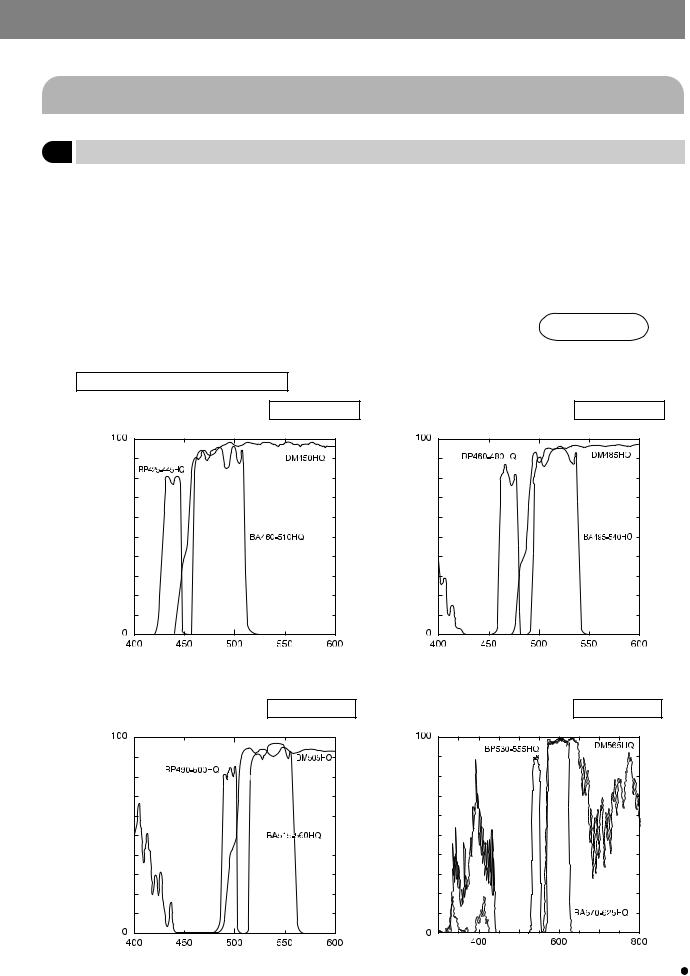
Spectral Characteristics of the Filters
1. Filter for fluorescent protein CFP U-MCFPHQ/XL
Transmittance %
Wavelength nm
3. Filter for fluorescent protein YFP U-MYFPHQ/XL
Transmittance %
2. Filter for fluorescent protein GFP U-MGFPHQ/XL
Transmittance %
Wavelength nm
4. Filter for fluorescent protein RFP U-MRFPHQ/XL
Transmittance % |
12 |
Wavelength nm |
Wavelength nm |
|
|
|
|
|
 Loading...