


NSC LMV110M5, LMV105M7X, LMV105M5X, LMV105M5, LMV102M7X Datasheet
...
December 1999
LMV101/102/105/110
Fixed-Gain Amplifiers
General Description
The LMV101/102/105/110 fixed-gain amplifier family integrates a rail-to-rail op amp, two internal gain-setting resistors and a V+/2 bias circuit into one ultra tiny package, SC70-5 or SOT23-5. Fixed inverting gains of −1, −2, −5, and −10 are available.
The core op amp in this series is an LMV321, which provides rail-to-rail output swing, excellent speed-power ratio, 1MHz bandwidth, and 1V/µs of slew rate with low supply current.
The LMV101/102/105/110 family reduces external component count. It is the most cost effective solution for applications where low voltage operation, low power consumption, space savings, and reliable performance are needed. It enables the design of small portable electronic devices, and allows the designer to place the device closer to the signal source to reduce noise pickup and increase signal integrity.
Features
(For 5V Supply, Typical Unless Otherwise Noted) |
|
|
n Fixed inverting gain available |
−1,−2,−5,−10 |
|
n DC gain accuracy @2.7V supply |
|
|
Ð LMV101/102/105 |
2 |
% (typ) |
Ð LMV110 |
6 |
% (typ) |
n Space saving packages |
SC70-5 & SOT23-5 |
|
n Industrial temperature range |
−40ÊC to +85ÊC |
|
n Low supply current |
|
130µA |
nRail-to-Rail output swing
nGuaranteed 2.7V and 5V performance
Applications
nGeneral purpose portable devices
nMobile communications
nBattery powered electronics
nActive filters
nMicrophone preamplifiers
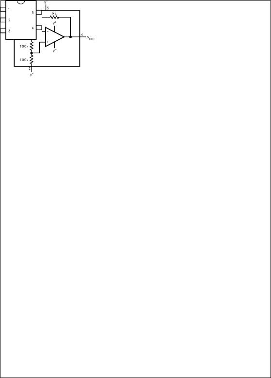
Typical Application
Phase Inverting AC Amplifier
DS101234-10
VOUT = 0.5VCC −V IN (R2/R1)
Amplifiers Gain-Fixed LMV101/102/105/110
© 1999 National Semiconductor Corporation |
DS101234 |
www.national.com |
LMV101/102/105/110
Connection Diagrams
DS101234-2
DS101234-1
5-Pin SC70-5 (M7)
DS101234-3
5-Pin SOT23-5 (M5)
Ordering Information |
|
|
|
|
|
|
||
Package |
Part number |
|
Marking |
DC Gain |
R1 |
R2 |
Transport Media |
NSC |
|
|
Drawing |
||||||
|
|
|
|
|
|
|
|
|
|
|
|
|
|
|
|
|
|
|
LMV101M7 |
|
A38 |
−1 |
100k |
100k |
1k Units Tape and Reel |
|
|
|
|
|
|
||||
|
LMV101M7X |
|
3k Units Tape and Reel |
|
||||
|
|
|
|
|
|
|
||
|
|
|
|
|
|
|
|
|
|
LMV102M7 |
|
A39 |
−2 |
100k |
200k |
1k Units Tape and Reel |
|
|
|
|
|
|
||||
SC70-5 |
LMV102M7X |
|
3k Units Tape and Reel |
MAA05A |
||||
|
|
|
|
|
||||
|
|
|
|
|
|
|
||
LMV105M7 |
|
A40 |
−5 |
50k |
250k |
1k Units Tape and Reel |
||
|
|
|
||||||
|
|
|
|
|
||||
|
LMV105M7X |
|
3k Units Tape and Reel |
|
||||
|
|
|
|
|
|
|
||
|
|
|
|
|
|
|
|
|
|
LMV110M7 |
|
A41 |
−10 |
10k |
100k |
1k Units Tape and Reel |
|
|
|
|
|
|
||||
|
LMV110M7X |
|
3k Units Tape and Reel |
|
||||
|
|
|
|
|
|
|
||
|
|
|
|
|
|
|
|
|
|
LMV101M5 |
|
A33A |
−1 |
100k |
100k |
1k Units Tape and Reel |
|
|
|
|
|
|
||||
|
LMV101M5X |
|
3k Units Tape and Reel |
|
||||
|
|
|
|
|
|
|
||
|
|
|
|
|
|
|
|
|
|
LMV102M5 |
|
A34A |
−2 |
100k |
200k |
1k Units Tape and Reel |
|
|
|
|
|
|
||||
SOT23-5 |
LMV102M5X |
|
3k Units Tape and Reel |
MA05B |
||||
|
|
|
|
|
||||
|
|
|
|
|
|
|
||
LMV105M5 |
|
A35A |
−5 |
50k |
250k |
1k Units Tape and Reel |
||
|
|
|
||||||
|
|
|
|
|
||||
|
LMV105M5X |
|
3k Units Tape and Reel |
|
||||
|
|
|
|
|
|
|
||
|
|
|
|
|
|
|
|
|
|
LMV110M5 |
|
A36A |
−10 |
10k |
100k |
1k Units Tape and Reel |
|
|
|
|
|
|
||||
|
LMV110M5X |
|
3k Units Tape and Reel |
|
||||
|
|
|
|
|
|
|
||
|
|
|
|
|
|
|
|
|
www.national.com |
2 |

Absolute Maximum Ratings (Note 1)
If Military/Aerospace specified devices are required, please contact the National Semiconductor Sales Office/ Distributors for availability and specifications.
ESD Tolerance (Note 2) |
|
Machine Model |
200V |
Human Body Model |
1500V |
Supply Voltage (V + - V− ) |
5.5V |
Output Short Circuit to V + |
(Note 3) |
Output Short Circuit to V − |
(Note 4) |
Mounting Temperature |
|
Infrared or Convection (20 sec) |
235ÊC |
Storage Temperature Range |
-65ÊC to 150ÊC |
Junction Temperature (TJ , max) |
150ÊC |
(Note 5) |
|
Operating Ratings (Note 1)
Supply Voltage |
2.7V to 5.0V |
Temperature Range |
−40ÊC ≤ TJ ≤ 85ÊC |
Thermal resistance (θJA) |
|
5-pin SC70-5 |
478ÊC/W |
5-pin SOT23-5 |
265ÊC/W |
2.7V Electrical Characteristics
Unless otherwise specified, all limits guaranteed for TJ = 25ÊC, V+ = 2.7V, V− |
= 0V, VO = V +/2 and RL > 1MΩ. Boldface lim- |
|||||
its apply at the temperature extremes. |
|
|
|
|
|
|
Symbol |
Parameter |
Conditions |
|
Typ |
Max |
Units |
|
|
|
|
(Note 6) |
(Note 7) |
|
|
|
|
|
|
|
|
VO |
Output Swing |
RL = 10kΩ to 1.35V |
|
V+−0.01 |
V +−0.1 |
V |
|
|
|
|
|
|
min |
|
|
|
|
|
|
|
|
|
|
|
0.08 |
0.18 |
V |
|
|
|
|
|
|
max |
|
|
|
|
|
|
|
IS |
Supply Current |
|
|
80 |
170 |
µA |
|
|
|
|
|
|
max |
|
|
|
|
|
|
|
|
DC Gain Accuracy |
LMV101, Gain = −1 |
|
2 |
5 |
% |
|
|
|
|
|
|
|
|
|
LMV102, Gain = −2 |
|
2 |
5 |
% |
|
|
|
|
|
|
|
|
|
LMV105, Gain = −5 |
|
2 |
6 |
% |
|
|
|
|
|
|
|
|
|
LMV110, Gain = −10 |
|
6 |
12 |
% |
|
|
|
|
|
|
|
GBW |
−3dB Bandwidth |
LMV101, Gain = −1, |
|
1.6 |
|
MHz |
|
|
R L = 2kΩ, CL = 100pF |
|
|
|
|
|
|
LMV102, Gain = −2, |
|
1.8 |
|
MHz |
|
|
R L = 2kΩ, CL = 100pF |
|
|
|
|
|
|
LMV105, Gain = −5, |
|
0.8 |
|
MHz |
|
|
R L = 2kΩ, CL = 100pF |
|
|
|
|
|
|
LMV110, Gain = −10, |
|
0.2 |
|
MHz |
|
|
R L = 2kΩ, CL = 100pF |
|
|
|
|
5V Electrical Characteristics
Unless otherwise specified, all limits guaranteed for TJ = 25ÊC, V+ = 5V, V− = 0V, VO = V +/2 and RL > 1MΩ. Boldface limits apply at the temperature extremes.
Symbol |
Parameter |
Conditions |
Typ |
Max |
Units |
|
|
|
(Note 6) |
(Note 7) |
|
|
|
|
|
|
|
V O |
Output Swing |
RL = 2kΩ to 2.5V |
V+−0.04 |
V +−0.3 |
V |
|
|
|
|
V+−0.4 |
min |
|
|
|
0.14 |
0.3 |
V |
|
|
|
|
0.4 |
max |
|
|
|
|
|
|
|
|
RL = 10kΩ to 2.5V |
V+−0.01 |
V +−0.1 |
V |
|
|
|
|
V+−0.2 |
min |
|
|
|
0.1 |
0.18 |
V |
|
|
|
|
0.28 |
max |
|
|
|
|
|
|
IO |
Output Current |
Sourcing, VO = 0V |
60 |
5 |
mA |
|
|
|
|
|
min |
|
|
|
|
|
|
|
|
Sinking, VO = 5V |
160 |
10 |
mA |
|
|
|
|
|
min |
|
|
|
|
|
|
LMV101/102/105/110
3 |
www.national.com |
LMV101/102/105/110
5V Electrical Characteristics (Continued)
Unless otherwise specified, all limits guaranteed for TJ = 25ÊC, V+ = 5V, V− = 0V, VO = V +/2 and RL > 1MΩ. Boldface limits apply at the temperature extremes.
Symbol |
Parameter |
Conditions |
Typ |
Max |
Units |
|
|
|
(Note 6) |
(Note 7) |
|
|
|
|
|
|
|
IS |
Supply Current |
|
130 |
250 |
µA |
|
|
|
|
350 |
max |
|
|
|
|
|
|
|
DC Gain Accuracy |
LMV101, Gain = −1 |
3.5 |
5 |
% |
|
|
|
|
|
|
|
|
LMV102, Gain = −2 |
3.5 |
5 |
% |
|
|
|
|
|
|
|
|
LMV105, Gain = −5 |
3.5 |
6 |
% |
|
|
|
|
|
|
|
|
LMV110, Gain = −10 |
9.0 |
12 |
% |
|
|
|
|
|
|
SR |
Slew Rate |
(Note 8) |
1 |
|
V/µs |
|
|
|
|
|
|
GBW |
−3dB Bandwidth |
LMV101, Gain = −1, |
1.6 |
|
MHz |
|
|
R L = 2kΩ, CL = 100pF |
|
|
|
|
|
LMV102, Gain = −2, |
1.8 |
|
MHz |
|
|
R L = 2kΩ, CL = 100pF |
|
|
|
|
|
LMV105, Gain = −5, |
0.8 |
|
MHz |
|
|
R L = 2kΩ, CL = 100pF |
|
|
|
|
|
LMV110, Gain = −10, |
0.2 |
|
MHz |
|
|
R L = 2kΩ, CL = 100pF |
|
|
|
Note 1: Absolute Maximum Ratings indicate limits beyond which damage to the device may occur. Operating Ratings indicate conditions for which the device is intended to be functional, but specific performance is not guaranteed. For guaranteed specifications and the test conditions, see the Electrical Characteristics.
Note 2: Human body model, 1.5kΩ in series with 100pF. Machine model, 0Ω in series with 100pF.
Note 3: Shorting circuit output to V+ will adversely affect reliability.
Note 4: Shorting circuit output to V− will adversely affect reliability.
Note 5: The maximum power dissipation is a function of TJ(max) , θJA, and TA. The maximum allowable power dissipation at any ambient temperature is P D = (TJ(max)±T A)/θJA. All numbers apply for packages soldered directly into a PC board.
Note 6: Typical Values represent the most likely parametric norm.
Note 7: All limits are guaranteed by testing or statistical analysis.
Note 8: Number specified is the slower of the positive and negative slew rates.
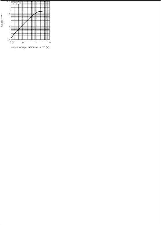
Typical Performance Characteristics (Unless otherwise specified, VS = +5V, single supply, TA = 25ÊC.)
Supply Current vs. |
Sourcing Current |
Supply Voltage |
vs. Output Voltage |
DS101234-22
DS101234-23
www.national.com |
4 |
 Loading...