


PRELIMINARY
April 1998
PC87309 SuperI/O Plug and Play Compatible Chip in Compact 100-Pin VLJ Packaging
Highlights
General Description
The PC87309 is a single-chip solution to the most commonly used ISA, EISA and MicroChannel® peripherals in a compact, 100-pin VLJ packaging. This fully Plug and Play (PnP) and PC97 compatible chip conforms to the Plug and Play ISA Specification Version 1.0a, May 5, 1994, and meets specifications defined in the PC97 Hardware Design Guide.
The PC87309 incorporates: a Floppy Disk Controller (FDC), a Mouse and Keyboard Controller (KBC), two enhanced UARTs, one of which is with Infrared (IR) support, a full IEEE 1284 parallel port and support for Power Management (PM). The chip also provides a separate configuration register set for each module.
The Infrared (IR) interface complies with the HP-SIR and SHARP-IR standards, and supports all four basic protocols for Consumer Remote Control circuitry (RC-5, RC-6, NEC, RCA and RECS 80).
For flexible UART and IR support, the PC87309 offers two operation modes:
●Mode 1: Full-IR Mode
UART1 works as UART; UART2 works as fully IRcompliant device
●Mode 2: Two-UART Mode
Either both UARTs work as UARTs, or UART1 works as UART and UART2 works as partially IR-compliant device, providing only IRRX and IRTX support
Outstanding Features
●Full SuperI/O functionality in compact, cost-effective 100-pin VLJ packaging
●PC97 compliant
PC87309 Block Diagram
|
DMA |
Floppy Drive |
|
Data Handshake |
|||||
IRQ Channels |
Interface |
|
|||||||
|
|
|
|
|
|
|
|
|
|
|
|
|
|
|
|
|
|
|
|
|
|
|
|
|
|
|
|
|
|
Plug and Play |
|
Floppy Disk |
|
High Current Driver |
|||||
|
|
|
|
|
|||||
|
|
|
IEEE 1284 |
||||||
|
Controller (FDC) |
|
|
||||||
|
(PnP) |
|
|
|
|||||
|
|
|
|
Parallel Port |
|||||
|
|
(Logical Device 0) |
|
|
|||||
|
|
|
|
|
(Logical Device 1) |
||||
|
|
|
|
|
|
|
|||
μP Address
Data and
Control
|
Serial Port |
|
|
|
|
Power Management |
|
Mouse and Keyboard |
|||||
|
|
Serial Port |
|
|
|||||||||
with IR (UART2) |
|
(UART1) |
|
(PM) Logic |
|
Controller (KBC) |
|||||||
(Logical Devices 2) |
|
(Logical Devices 3) |
|
(Logical Device 4) |
|
(Logical Devices 5 & 6) |
|||||||
|
|
|
|
|
|
|
|
|
|
|
|
|
|
|
|
|
|
|
|
|
|
|
|
|
|
|
|
|
|
|
|
|
|
|
|
|
|
|
|
|
|
Serial Infrared |
|
|
|
|
|
|
|
Data and |
Ports |
||||
|
Serial |
Control |
|
||||||||||
|
|
|
|
Interface |
|
|
|
Control |
|
|
|||
TRI-STATE® is a registered trademark of National Semiconductor Corporation.
IBM®, MicroChannel®, PC-AT® and PS/2® are registered trademarks of International Business Machines Corporation. Microsoft® and Windows® are registered trademarks of Microsoft Corporation.
Highlights
© 1998 National Semiconductor Corporation |
www.national.com |

Highlights
Features
●100% compatibility with PnP requirements specified in the “Plug and Play ISA Specification”, PC97, ISA, EISA, and MicroChannel architectures
●A special PnP module that includes:
—Flexible IRQs, DMAs and base addresses that meet the PnP requirements specified by Microsoft® in their 1995 hardware design guide for Windows® and PnP ISA Revision 1.0A
—PnP ISA mode (with isolation mechanism – Wait for Key state Motherboard PnP mode
●A Floppy Disk Controller (FDC) that provides:
—A relocatable address that is referenced by an 11-bit programmable register
—Software compatibility with the PC8477, which con-
tains a superset of the floppy disk controller functions in the μDP8473, the NEC μPD765A and the N82077
—7 IRQ channel options
—Three 8-bit DMA channel options
—16-byte FIFO
—Burst and non-burst modes
—A new high-performance, on-chip, digital data separator that does not require any external filter components
—Support for standard 5.25" and 3.5" floppy disk drives
—Perpendicular recording drive support
—Three-mode Floppy Disk Drive (FDD) support
—Full support for the IBM Tape Drive Register (TDR) implementation of AT and PS/2 drive types
●A Keyboard and mouse Controller (KBC) with:
—A relocatable address that is referenced by an 11-bit programmable register, reported as a fixed address in resource data
—7 IRQ options for the keyboard controller
—7 IRQ options for the mouse controller
—An 8-bit microcontroller
—Software compatibility with the 8042AH and PC87911 microcontrollers
—2 KB of custom-designed program ROM
—256 bytes of RAM for data
—Three programmable dedicated open drain I/O lines for keyboard controller applications
—Asynchronous access to two data registers and one status register during normal operation
—Support for both interrupt and polling
—93 instructions
—An 8-bit timer/counter
—Support for binary and BCD arithmetic
—Operation at 8 MHz,12 MHz or 16 MHz (programmable option)
—Customizing by using the PC87323VUL, which includes a RAM-based KBC, as a development platform for keyboard controller code for the PC87309
●Two UARTs that provide:
—Software compatibility with the 16550A and the 16450
—A relocatable address that is referenced by an 11-bit programmable register
—7 IRQ channel options
—Shadow register support for write-only bit monitoring
—UART data rates up to 1.5 Mbaud
●An enhanced UART and Infrared (IR) interface on the UART2 that supports:
—HP-SIR
—ASK-IR option of SHARP-IR
—DASK-IR option of SHARP-IR
—Consumer Remote Control circuitry
—A PnP compatible external transceiver
—Three 8-bit DMA options for the UART with Slow Infrared support (UART2)
●A bidirectional parallel port that includes:
—A relocatable address that is referenced by an 11-bit programmable register
—Software or hardware control
—7 IRQ channel options
—Three 8-bit DMA channel options
—Demand mode DMA support
—An Enhanced Parallel Port (EPP) that is compatible with the new version EPP 1.9, and is IEEE 1284 compliant
—An Enhanced Parallel Port (EPP) that also supports version EPP 1.7 of the Xircom specification.
—Support for an Enhanced Parallel Port (EPP) as mode 4 of the Extended Capabilities Port (ECP)
—An Extended Capabilities Port (ECP) that is IEEE 1284 compliant, including level 2
—Selection of internal pull-up or pull-down resistor for Paper End (PE) pin
—Reduction of PCI bus utilization by supporting a demand DMA mode mechanism and a DMA fairness mechanism
—A protection circuit that prevents damage to the parallel port when a printer connected to it powers up or is operated at high voltages
—Output buffers that can sink and source 14 mA
●Enhanced Power Management (PM), including:
—Reduced current leakage from pins
—Low-power CMOS technology
—Ability to shut off clocks to all modules
●Clock source:
—Source is a 48 MHz clock input signal.
●General features include:
—Access to all configuration registers is through an Index and a Data register, which can be relocated within the ISA I/O address space
—100-pin Plastic Quad Flatpack (PQFP) package
www.national.com |
2 |

|
Highlights |
|
|
Basic Configuration |
|
|
|
|
|
P12 |
|
|
|
P21,20 |
|
|
|
|
Keyboard I/O |
48 MHz |
CLKIN |
KBCLK |
Interface |
Clock |
|
KBDAT |
|
|
|
|
|
|
|
MDAT |
|
|
|
MCLK |
|
|
MR |
SIN1 |
|
|
AEN |
|
|
|
SOUT1 |
|
|
|
A11-0 |
|
|
|
RTS1 |
|
|
|
D7-0 |
EIA |
|
|
DTR1/BOUT1 |
||
|
RD |
||
|
Drivers |
||
|
CTS1 |
||
|
WR |
||
|
|
||
|
IOCHRDY |
DSR1 |
|
|
|
DCD1 |
|
Bus |
IRQ1 |
RI1 |
|
IRQ7-3 |
IRRX2,1 |
|
|
IRQ12 |
|
||
ISA |
DRQ3-1 |
IRTX |
Infrared (IR) |
DACK3-1 |
IRSL2-0 |
Interface |
|
|
TC |
|
|
|
ID3-0 |
|
|
|
PC87309 |
|
|
|
SIN2 |
|
|
|
|
|
|
|
|
SOUT2 |
|
|
PD7-0 |
RTS2 |
EIA |
|
DTR2/BOUT2 |
||
|
SLIN/ASTRB |
Drivers |
|
|
CTS2 |
||
|
STB/WRITE |
|
|
|
DSR2 |
|
|
Parallel |
AFD/DSTRB |
|
|
DCD2 |
|
||
INIT |
|
||
Port |
RI2 |
|
|
|
|
||
Connector |
ACK |
RDATA |
|
|
ERR |
|
|
|
WDATA |
|
|
|
SLCT |
|
|
|
WGATE |
|
|
|
PE |
|
|
|
HDSEL |
|
|
|
BUSY/WAIT |
Floppy |
|
|
DIR |
||
|
|
Disk |
|
|
|
STEP |
|
|
|
TRK0 |
Controller |
|
|
(FDC) |
|
|
|
INDEX |
|
|
|
Connector |
|
|
|
DSKCHG |
|
Configuration |
BADDR1,0 |
|
|
WP |
|
||
Select Logic |
CFG0 |
|
|
MTR1,0 |
|
||
|
|
|
|
|
|
DR1,0 |
|
|
|
DENSEL |
|
|
|
DRATE0 |
|
|
3 |
|
www.national.com |

Table of Contents
Table of Contents
Highlights....................................................................................................................................................... |
1 |
1.0Signal/Pin Connection and Description
1.1 |
CONNECTION DIAGRAM ......................................................................................................... |
12 |
1.2 |
SIGNAL/PIN DESCRIPTIONS ................................................................................................... |
13 |
2.0Configuration
2.1 |
HARDWARE CONFIGURATION ............................................................................................... |
19 |
|
|
2.1.1 |
Wake Up Options ........................................................................................................ |
19 |
|
2.1.2 The Index and Data Register Pair ............................................................................... |
19 |
|
2.2 |
SOFTWARE CONFIGURATION ............................................................................................... |
20 |
|
|
2.2.1 Accessing the Configuration Registers ........................................................................ |
20 |
|
|
2.2.2 |
Address Decoding ....................................................................................................... |
20 |
2.3 |
THE CONFIGURATION REGISTERS ....................................................................................... |
21 |
|
|
2.3.1 Standard Plug and Play (PnP) Register Definitions .................................................... |
21 |
|
|
2.3.2 |
Configuration Register Summary ................................................................................ |
25 |
2.4 |
CARD CONTROL REGISTERS ................................................................................................ |
28 |
|
|
2.4.1 |
SID Register ................................................................................................................ |
28 |
|
2.4.2 SuperI/O Configuration 1 Register (SIOCF1) .............................................................. |
28 |
|
|
2.4.3 SuperI/O Configuration 2 Register (SIOCF2) .............................................................. |
29 |
|
|
2.4.4 |
SRID Register .............................................................................................................. |
29 |
2.5 |
FDC CONFIGURATION REGISTERS (LOGICAL DEVICE 0) .................................................. |
30 |
|
|
2.5.1 SuperI/O FDC Configuration Register ......................................................................... |
30 |
|
|
2.5.2 |
Drive ID Register ......................................................................................................... |
30 |
2.6 |
SUPERI/O PARALLEL PORT CONFIGURATION REGISTER (LOGICAL DEVICE 1) ............. |
30 |
|
2.7 |
SUPERI/O UART2 AND INFRARED CONFIGURATION REGISTER (LOGICAL DEVICE 2) .. |
31 |
|
2.8 |
SUPERI/O UART1 CONFIGURATION REGISTER (LOGICAL DEVICE 3) .............................. |
32 |
|
2.9 |
SUPERI/O KBC CONFIGURATION REGISTER (LOGICAL DEVICE 6) .................................. |
32 |
|
2.10 |
CONFIGURATION REGISTER BITMAPS ................................................................................ |
32 |
|
3.0The Floppy Disk Controller (FDC) (Logical Device 0)
3.1 |
FDC FUNCTIONS ..................................................................................................................... |
34 |
|
|
3.1.1 |
Microprocessor Interface ............................................................................................. |
34 |
|
3.1.2 |
System Operation Modes ............................................................................................ |
34 |
3.2 |
DATA TRANSFER ..................................................................................................................... |
35 |
|
|
3.2.1 |
Data Rates ................................................................................................................... |
35 |
|
3.2.2 |
The Data Separator ..................................................................................................... |
35 |
|
3.2.3 Perpendicular Recording Mode Support ..................................................................... |
36 |
|
|
3.2.4 |
Data Rate Selection ..................................................................................................... |
36 |
|
3.2.5 |
Write Precompensation ............................................................................................... |
37 |
|
3.2.6 FDC Low-Power Mode Logic ....................................................................................... |
37 |
|
|
3.2.7 |
Reset ........................................................................................................................... |
37 |
3.3 |
THE REGISTERS OF THE FDC ............................................................................................... |
37 |
|
www.national.com |
4 |

Table of Contents
|
3.3.1 |
Status Register A (SRA) .............................................................................................. |
38 |
|
3.3.2 |
Status Register B (SRB) .............................................................................................. |
39 |
|
3.3.3 |
Digital Output Register (DOR) ..................................................................................... |
39 |
|
3.3.4 |
Tape Drive Register (TDR) .......................................................................................... |
41 |
|
3.3.5 |
Main Status Register (MSR) ........................................................................................ |
42 |
|
3.3.6 |
Data Rate Select Register (DSR) ................................................................................ |
43 |
|
3.3.7 |
Data Register (FIFO) ................................................................................................... |
43 |
|
3.3.8 |
Digital Input Register (DIR) .......................................................................................... |
44 |
|
3.3.9 |
Configuration Control Register (CCR) ......................................................................... |
45 |
3.4 THE PHASES OF FDC COMMANDS ....................................................................................... |
45 |
||
|
3.4.1 |
Command Phase ......................................................................................................... |
45 |
|
3.4.2 |
Execution Phase .......................................................................................................... |
45 |
|
3.4.3 |
Result Phase ............................................................................................................... |
47 |
|
3.4.4 |
Idle Phase .................................................................................................................... |
47 |
|
3.4.5 |
Drive Polling Phase ..................................................................................................... |
48 |
3.5 THE RESULT PHASE STATUS REGISTERS .......................................................................... |
48 |
||
|
3.5.1 |
Result Phase Status Register 0 (ST0) ......................................................................... |
48 |
|
3.5.2 |
Result Phase Status Register 1 (ST1) ......................................................................... |
49 |
|
3.5.3 |
Result Phase Status Register 2 (ST2) ......................................................................... |
49 |
|
3.5.4 |
Result Phase Status Register 3 (ST3) ......................................................................... |
50 |
3.6 |
FDC REGISTER BITMAPS ....................................................................................................... |
51 |
|
|
3.6.1 |
Standard ...................................................................................................................... |
51 |
|
3.6.2 |
Result Phase Status .................................................................................................... |
52 |
3.7 |
COMMAND SET ....................................................................................................................... |
53 |
|
|
3.7.1 |
Abbreviations Used in FDC Commands ...................................................................... |
54 |
|
3.7.2 |
The CONFIGURE Command ...................................................................................... |
55 |
|
3.7.3 |
The DUMPREG Command ......................................................................................... |
55 |
|
3.7.4 |
The FORMAT TRACK Command ............................................................................... |
56 |
|
3.7.5 |
The INVALID Command .............................................................................................. |
58 |
|
3.7.6 |
The LOCK Command .................................................................................................. |
60 |
|
3.7.7 |
The MODE Command ................................................................................................. |
60 |
|
3.7.8 |
The NSC Command .................................................................................................... |
62 |
|
3.7.9 |
The PERPENDICULAR MODE Command ................................................................. |
62 |
|
3.7.10 |
The READ DATA Command ....................................................................................... |
64 |
|
3.7.11 |
The READ DELETED DATA Command ...................................................................... |
66 |
|
3.7.12 |
The READ ID Command ............................................................................................. |
67 |
|
3.7.13 |
The READ A TRACK Command ................................................................................. |
68 |
|
3.7.14 |
The RECALIBRATE Command ................................................................................... |
68 |
|
3.7.15 |
The RELATIVE SEEK Command ................................................................................ |
69 |
3.7.16The SCAN EQUAL, the SCAN LOW OR EQUAL and the SCAN HIGH OR EQUAL
|
Commands .................................................................................................................. |
69 |
3.7.17 |
The SEEK Command .................................................................................................. |
70 |
3.7.18 The SENSE DRIVE STATUS Command .................................................................... |
71 |
|
3.7.19 The SENSE INTERRUPT Command .......................................................................... |
71 |
|
3.7.20 The SET TRACK Command ........................................................................................ |
72 |
|
3.7.21 |
The SPECIFY Command ............................................................................................ |
73 |
3.7.22 |
The VERIFY Command ............................................................................................... |
74 |
5 |
www.national.com |

Table of Contents
3.7.23 |
The VERSION Command ............................................................................................ |
76 |
3.7.24 The WRITE DATA Command ...................................................................................... |
76 |
|
3.7.25 |
The WRITE DELETED DATA Command .................................................................... |
77 |
3.8 EXAMPLE OF A FOUR-DRIVE CIRCUIT USING THE PC87309 ............................................. |
78 |
|
4.0Parallel Port (Logical Device 1)
4.1 |
PARALLEL PORT CONFIGURATION ...................................................................................... |
79 |
|
|
4.1.1 |
Parallel Port Operation Modes .................................................................................... |
79 |
|
4.1.2 |
Configuring Operation Modes ...................................................................................... |
79 |
|
4.1.3 |
Output Pin Protection .................................................................................................. |
79 |
4.2 STANDARD PARALLEL PORT (SPP) MODES ........................................................................ |
79 |
||
|
4.2.1 |
SPP Modes Register Set ............................................................................................. |
80 |
|
4.2.2 |
SPP Data Register (DTR) ............................................................................................ |
80 |
|
4.2.3 |
Status Register (STR) ................................................................................................. |
81 |
|
4.2.4 |
SPP Control Register (CTR) ........................................................................................ |
81 |
4.3 ENHANCED PARALLEL PORT (EPP) MODES ........................................................................ |
82 |
||
|
4.3.1 |
EPP Register Set ......................................................................................................... |
82 |
|
4.3.2 |
SPP or EPP Data Register (DTR) ............................................................................... |
83 |
|
4.3.3 |
SPP or EPP Status Register (STR) ............................................................................. |
83 |
|
4.3.4 |
SPP or EPP Control Register (CTR) ........................................................................... |
83 |
|
4.3.5 |
EPP Address Register (ADDR) ................................................................................... |
83 |
|
4.3.6 |
EPP Data Register 0 (DATA0) .................................................................................... |
84 |
|
4.3.7 |
EPP Data Register 1 (DATA1) .................................................................................... |
84 |
|
4.3.8 |
EPP Data Register 2 (DATA2) .................................................................................... |
84 |
|
4.3.9 |
EPP Data Register 3 (DATA3) .................................................................................... |
84 |
|
4.3.10 |
EPP Mode Transfer Operations .................................................................................. |
85 |
|
4.3.11 |
EPP 1.7 and 1.9 Data Write and Read Operations ..................................................... |
85 |
4.4 EXTENDED CAPABILITIES PARALLEL PORT (ECP) ............................................................. |
86 |
||
|
4.4.1 |
ECP Modes ................................................................................................................. |
86 |
|
4.4.2 |
Software Operation ...................................................................................................... |
86 |
|
4.4.3 |
Hardware Operation .................................................................................................... |
87 |
4.5 |
ECP MODE REGISTERS .......................................................................................................... |
87 |
|
|
4.5.1 |
Accessing the ECP Registers ...................................................................................... |
87 |
|
4.5.2 |
Second Level Offsets .................................................................................................. |
88 |
|
4.5.3 |
ECP Data Register (DATAR) ....................................................................................... |
88 |
|
4.5.4 |
ECP Address FIFO (AFIFO) Register ......................................................................... |
88 |
|
4.5.5 |
ECP Status Register (DSR) ......................................................................................... |
88 |
|
4.5.6 |
ECP Control Register (DCR) ....................................................................................... |
89 |
|
4.5.7 |
Parallel Port Data FIFO (CFIFO) Register ................................................................... |
90 |
|
4.5.8 |
ECP Data FIFO (DFIFO) Register ............................................................................... |
90 |
|
4.5.9 |
Test FIFO (TFIFO) Register ........................................................................................ |
90 |
|
4.5.10 |
Configuration Register A (CNFGA) ............................................................................. |
90 |
|
4.5.11 |
Configuration Register B (CNFGB) ............................................................................. |
91 |
|
4.5.12 |
Extended Control Register (ECR) ............................................................................... |
91 |
|
4.5.13 |
ECP Extended Index Register (EIR) ........................................................................... |
92 |
|
4.5.14 |
ECP Extended Data Register (EDR) ........................................................................... |
93 |
www.national.com |
6 |

Table of Contents
4.5.15 |
ECP Extended Auxiliary Status Register (EAR) .......................................................... |
93 |
4.5.16 |
Control0 Register ......................................................................................................... |
93 |
4.5.17 |
Control2 Register ......................................................................................................... |
93 |
4.5.18 |
Control4 Register ......................................................................................................... |
94 |
4.5.19 |
PP Confg0 Register ..................................................................................................... |
94 |
4.6 DETAILED ECP MODE DESCRIPTIONS ................................................................................. |
95 |
|
4.6.1 |
Software Controlled Data Transfer (Modes 000 and 001) ........................................... |
95 |
4.6.2 |
Automatic Data Transfer (Modes 010 and 011) .......................................................... |
95 |
4.6.3 |
Automatic Address and Data Transfers (Mode 100) ................................................... |
97 |
4.6.4 |
FIFO Test Access (Mode 110) .................................................................................... |
97 |
4.6.5 |
Configuration Registers Access (Mode 111) ............................................................... |
97 |
4.6.6 |
Interrupt Generation .................................................................................................... |
97 |
4.7 PARALLEL PORT REGISTER BITMAPS ................................................................................. |
98 |
|
4.7.1 |
EPP Modes .................................................................................................................. |
98 |
4.7.2 |
ECP Modes ................................................................................................................. |
99 |
4.8 PARALLEL PORT PIN/SIGNAL LIST ...................................................................................... |
101 |
|
5.0Enhanced Serial Port with IR -UART2 (Logical Device 2)
5.1 |
FEATURES .............................................................................................................................. |
102 |
|
5.2 |
FUNCTIONAL MODES OVERVIEW ....................................................................................... |
102 |
|
|
5.2.1 |
UART Modes: 16450 or 16550, and Extended .......................................................... |
102 |
|
5.2.2 |
Sharp-IR, IrDA SIR Infrared Modes ........................................................................... |
102 |
|
5.2.3 |
Consumer IR Mode ................................................................................................... |
102 |
5.3 |
REGISTER BANK OVERVIEW ............................................................................................... |
102 |
|
5.4 |
UART MODES – DETAILED DESCRIPTION .......................................................................... |
104 |
|
|
5.4.1 |
16450 or 16550 UART Mode ..................................................................................... |
104 |
|
5.4.2 |
Extended UART Mode ............................................................................................... |
104 |
5.5 |
SHARP-IR MODE – DETAILED DESCRIPTION ..................................................................... |
105 |
|
5.6 |
SIR MODE – DETAILED DESCRIPTION ................................................................................ |
105 |
|
5.7 |
CONSUMER-IR MODE – DETAILED DESCRIPTION ............................................................ |
105 |
|
|
5.7.1 |
Consumer-IR Transmission ....................................................................................... |
105 |
|
5.7.2 |
Consumer-IR Reception ............................................................................................ |
106 |
5.8 |
FIFO TIME-OUTS .................................................................................................................... |
106 |
|
|
5.8.1 |
UART, SIR or Sharp-IR Mode Time-Out Conditions ................................................. |
106 |
|
5.8.2 |
Consumer-IR Mode Time-Out Conditions ................................................................. |
106 |
|
5.8.3 |
Transmission Deferral ............................................................................................... |
107 |
5.9 |
AUTOMATIC FALLBACK TO A NON-EXTENDED UART MODE .......................................... |
107 |
|
5.11 |
BANK 0 – GLOBAL CONTROL AND STATUS REGISTERS ................................................. |
107 |
|
|
5.11.1 |
Receiver Data Port (RXD) or the Transmitter Data Port (TXD) ................................. |
108 |
|
5.11.2 |
Interrupt Enable Register (IER) ................................................................................. |
108 |
|
5.11.3 |
Event Identification Register (EIR) ............................................................................ |
110 |
|
5.11.4 |
FIFO Control Register (FCR) ..................................................................................... |
112 |
|
5.11.5 |
Link Control Register (LCR) and Bank Selection Register (BSR) ............................. |
112 |
|
5.11.6 |
Bank Selection Register (BSR) ................................................................................. |
113 |
|
5.11.7 |
Modem/Mode Control Register (MCR) ...................................................................... |
114 |
7 |
www.national.com |

Table of Contents
5.11.8 |
Link Status Register (LSR) ........................................................................................ |
115 |
5.11.9 |
Modem Status Register (MSR) .................................................................................. |
116 |
5.11.10 |
Scratchpad Register (SPR) ....................................................................................... |
117 |
5.11.11 |
Auxiliary Status and Control Register (ASCR) .......................................................... |
117 |
5.12 BANK 1 – THE LEGACY BAUD GENERATOR DIVISOR PORTS ......................................... |
117 |
|
5.12.1Legacy Baud Generator Divisor Ports (LBGD(L) and LBGD(H)), .............................. 118
5.12.2 Link Control Register (LCR) and Bank Select Register (BSR) .................................. |
118 |
|
5.13 BANK 2 – EXTENDED CONTROL AND STATUS REGISTERS ............................................ |
118 |
|
5.13.1 Baud Generator Divisor Ports, LSB (BGD(L)) and MSB (BGD(H)) ........................... |
119 |
|
5.13.2 Extended Control Register 1 (EXCR1) ...................................................................... |
120 |
|
5.13.3 Link Control Register (LCR) and Bank Select Register (BSR) .................................. |
121 |
|
5.13.4 Extended Control and Status Register 2 (EXCR2) .................................................... |
121 |
|
5.13.5 |
Reserved Register ..................................................................................................... |
121 |
5.13.6 TX_FIFO Current Level Register (TXFLV) ................................................................ |
121 |
|
5.13.7 RX_FIFO Current Level Register (RXFLV) ............................................................... |
122 |
|
5.14 BANK 3 – MODULE REVISION ID AND SHADOW REGISTERS .......................................... |
122 |
|
5.14.1 Module Revision ID Register (MRID) ........................................................................ |
122 |
|
5.14.2 Shadow of Link Control Register (SH_LCR) ............................................................. |
122 |
|
5.14.3 Shadow of FIFO Control Register (SH_FCR) ............................................................ |
123 |
|
5.14.4 Link Control Register (LCR) and Bank Select Register (BSR) .................................. |
123 |
|
5.15 BANK 4 – IR MODE SETUP REGISTER ................................................................................ |
123 |
|
5.15.1 |
Reserved Registers ................................................................................................... |
123 |
5.15.2 Infrared Control Register 1 (IRCR1) .......................................................................... |
123 |
|
5.15.3 Link Control Register (LCR) and Bank Select Register (BSR) .................................. |
123 |
|
5.15.4 |
Reserved Registers ................................................................................................... |
123 |
5.16 BANK 5 – INFRARED CONTROL REGISTERS ..................................................................... |
123 |
|
5.16.1 |
Reserved Registers ................................................................................................... |
124 |
5.16.2 |
(LCR/BSR) Register .................................................................................................. |
124 |
5.16.3 Infrared Control Register 2 (IRCR2) .......................................................................... |
124 |
|
5.16.4 |
Reserved Registers ................................................................................................... |
124 |
5.17 BANK 6 – INFRARED PHYSICAL LAYER CONFIGURATION REGISTERS ......................... |
124 |
|
5.17.1 Infrared Control Register 3 (IRCR3) .......................................................................... |
124 |
|
5.17.2 |
Reserved Register ..................................................................................................... |
124 |
5.17.3 SIR Pulse Width Register (SIR_PW) ......................................................................... |
124 |
|
5.17.4 Link Control Register (LCR) and Bank Select Register (BSR) .................................. |
125 |
|
5.17.5 |
Reserved Registers ................................................................................................... |
125 |
5.18BANK 7 – CONSUMER-IR AND OPTICAL TRANSCEIVER CONFIGURATION REGISTERS 125
5.18.1 Infrared Receiver Demodulator Control Register (IRRXDC) ..................................... |
125 |
5.18.2 Infrared Transmitter Modulator Control Register (IRTXMC) ...................................... |
126 |
5.18.3 Consumer-IR Configuration Register (RCCFG) ........................................................ |
128 |
5.18.4 Link Control/Bank Select Registers (LCR/BSR) ........................................................ |
129 |
5.18.5 Infrared Interface Configuration Register 1 (IRCFG1) ............................................... |
129 |
5.18.6 Reserved Register ..................................................................................................... |
129 |
5.18.7 Infrared Interface Configuration 3 Register (IRCFG3) ............................................... |
129 |
5.18.8 Infrared Interface Configuration Register 4 (IRCFG4) ............................................... |
130 |
5.19 UART2 WITH IR REGISTER BITMAPS .................................................................................. |
131 |
www.national.com |
8 |

Table of Contents
6.0Enhanced Serial Port - UART1 (Logical Device 3)
6.1 |
REGISTER BANK OVERVIEW ............................................................................................... |
136 |
|
6.2 |
DETAILED DESCRIPTION ...................................................................................................... |
136 |
|
|
6.2.1 |
16450 or 16550 UART Mode ..................................................................................... |
137 |
|
6.2.2 |
Extended UART Mode ............................................................................................... |
137 |
6.3 |
FIFO TIME-OUTS .................................................................................................................... |
137 |
|
6.4 |
AUTOMATIC FALLBACK TO A NON-EXTENDED UART MODE .......................................... |
138 |
|
|
6.4.1 |
Transmission Deferral ............................................................................................... |
138 |
6.5 |
BANK 0 – GLOBAL CONTROL AND STATUS REGISTERS ................................................. |
138 |
|
|
6.5.1 |
Receiver Data Port (RXD) or the Transmitter Data Port (TXD) ................................. |
138 |
|
6.5.2 |
Interrupt Enable Register (IER) ................................................................................. |
139 |
|
6.5.3 |
Event Identification Register (EIR) ............................................................................ |
140 |
|
6.5.4 |
FIFO Control Register (FCR) ..................................................................................... |
142 |
|
6.5.5 |
Line Control Register (LCR) and Bank Selection Register (BSR) ............................. |
142 |
|
6.5.6 |
Bank Selection Register (BSR) ................................................................................. |
143 |
|
6.5.7 |
Modem/Mode Control Register (MCR) ...................................................................... |
143 |
|
6.5.8 |
Line Status Register (LSR) ........................................................................................ |
144 |
|
6.5.9 |
Modem Status Register (MSR) .................................................................................. |
145 |
|
6.5.10 |
Scratchpad Register (SPR) ....................................................................................... |
146 |
|
6.5.11 |
Auxiliary Status and Control Register (ASCR) .......................................................... |
146 |
6.6 |
BANK 1 – THE LEGACY BAUD GENERATOR DIVISOR PORTS ......................................... |
146 |
|
6.6.1Legacy Baud Generator Divisor Ports (LBGD(L) and LBGD(H)), .............................. 147
6.6.2 Line Control Register (LCR) and Bank Select Register (BSR) .................................. |
147 |
6.7 BANK 2 – EXTENDED CONTROL AND STATUS REGISTERS ............................................ |
148 |
6.7.1 Baud Generator Divisor Ports, LSB (BGD(L)) and MSB (BGD(H)) ........................... |
148 |
6.7.2 Extended Control Register 1 (EXCR1) ...................................................................... |
149 |
6.7.3 Line Control Register (LCR) and Bank Select Register (BSR) .................................. |
149 |
6.7.4 Extended Control and Status Register 2 (EXCR2) .................................................... |
149 |
6.7.5 Reserved Register ..................................................................................................... |
150 |
6.7.6 TX_FIFO Current Level Register (TXFLV) ................................................................ |
150 |
6.7.7 RX_FIFO Current Level Register (RXFLV) ............................................................... |
150 |
6.8 BANK 3 – MODULE REVISION ID AND SHADOW REGISTERS .......................................... |
150 |
6.8.1 Module Revision ID Register (MRID) ........................................................................ |
151 |
6.8.2 Shadow of Line Control Register (SH_LCR) ............................................................. |
151 |
6.8.3 Shadow of FIFO Control Register (SH_FCR) ............................................................ |
151 |
6.8.4 Line Control Register (LCR) and Bank Select Register (BSR) .................................. |
151 |
6.9 UART1 REGISTER BITMAPS ................................................................................................. |
151 |
7.0Power Management (Logical Device 4)
7.1 |
POWER MANAGEMENT OPTIONS ....................................................................................... |
155 |
7.2 |
THE POWER MANAGEMENT REGISTERS .......................................................................... |
155 |
|
7.2.1 Power Management Index Register .......................................................................... |
155 |
|
7.2.2 Power Management Data Register ........................................................................... |
155 |
|
7.2.3 Function Enable Register 1 (FER1) ........................................................................... |
155 |
|
7.2.4 Power Management Control Register (PMC1) .......................................................... |
156 |
9 |
www.national.com |

Table of Contents
7.2.5 Power Management Control 3 Register (PMC3) ....................................................... |
156 |
7.3 POWER MANAGEMENT REGISTER BITMAPS .................................................................... |
157 |
8.0Mouse and Keyboard Controller (KBC) (Logical Devices 5 and 6)
8.1 |
SYSTEM ARCHITECTURE ..................................................................................................... |
158 |
|
8.2 |
FUNCTIONAL OVERVIEW ..................................................................................................... |
159 |
|
8.3 |
DEVICE CONFIGURATION .................................................................................................... |
159 |
|
|
8.3.1 |
I/O Address Space .................................................................................................... |
159 |
|
8.3.2 |
Interrupt Request Signals .......................................................................................... |
159 |
|
8.3.3 |
KBC Clock ................................................................................................................. |
161 |
|
8.3.4 Timer or Event Counter ............................................................................................. |
161 |
|
8.4 |
EXTERNAL I/O INTERFACES ................................................................................................ |
161 |
|
|
8.4.1 Keyboard and Mouse Interface ................................................................................. |
161 |
|
|
8.4.2 General Purpose I/O Signals ..................................................................................... |
162 |
|
8.5 |
INTERNAL KBC - PC87309 INTERFACE ............................................................................... |
163 |
|
|
8.5.1 The KBC DBBOUT Register, Offset 60h, Read Only ................................................ |
163 |
|
|
8.5.2 The KBC DBBIN Register, Offset 60h (F1 Clear) or 64h (F1 Set), Write Only .......... |
163 |
|
|
8.5.3 The KBC STATUS Register ...................................................................................... |
163 |
|
8.6 |
INSTRUCTION TIMING ........................................................................................................... |
163 |
|
9.0Interrupt and DMA Mapping
9.1 |
IRQ MAPPING ......................................................................................................................... |
164 |
9.2 |
DMA MAPPING ....................................................................................................................... |
164 |
10.0 Device Specifications
10.1 GENERAL DC ELECTRICAL CHARACTERISTICS ............................................................... |
165 |
|
10.1.1 |
Recommended Operating Conditions ....................................................................... |
165 |
10.1.2 |
Absolute Maximum Ratings ....................................................................................... |
165 |
10.1.3 |
Capacitance ............................................................................................................... |
165 |
10.1.4 |
Power Consumption under Recommended Operating Conditions ............................ |
165 |
10.2 DC CHARACTERISTICS OF PINS, BY GROUP .................................................................... |
166 |
|
10.2.1 |
Group 1 ...................................................................................................................... |
166 |
10.2.2 |
Group 2 ...................................................................................................................... |
166 |
10.2.3 |
Group 3 ...................................................................................................................... |
166 |
10.2.4 |
Group 4 ...................................................................................................................... |
167 |
10.2.5 |
Group 5 ...................................................................................................................... |
167 |
10.2.6 |
Group 6 ...................................................................................................................... |
167 |
10.2.7 |
Group 7 ...................................................................................................................... |
168 |
10.2.8 |
Group 8 ...................................................................................................................... |
168 |
10.2.9 |
Group 9 ...................................................................................................................... |
169 |
10.2.10 |
Group 10 .................................................................................................................... |
169 |
10.2.11 |
Group 11 .................................................................................................................... |
169 |
10.2.12 |
Group 12 .................................................................................................................... |
169 |
10.2.13 |
Group 13 .................................................................................................................... |
170 |
10.2.14 |
Group 14 .................................................................................................................... |
170 |
www.national.com |
10 |
Table of Contents
10.2.15 |
Group 15 .................................................................................................................... |
170 |
10.2.16 |
Group 18 .................................................................................................................... |
170 |
10.3 AC ELECTRICAL CHARACTERISTICS .................................................................................. |
171 |
|
10.3.1 |
AC Test Conditions .................................................................................................... |
171 |
10.3.2 |
Clock Timing .............................................................................................................. |
171 |
10.3.3 |
Microprocessor Interface Timing ............................................................................... |
172 |
10.3.4 |
Baud Output Timing ................................................................................................... |
174 |
10.3.5 |
Transmitter Timing ..................................................................................................... |
175 |
10.3.6 |
Receiver Timing ......................................................................................................... |
176 |
10.3.7 |
UART, Sharp-IR, SIR and Consumer Remote Control Timing .................................. |
178 |
10.3.8 |
IRSLn Write Timing ................................................................................................... |
179 |
10.3.9 |
Modem Control Timing .............................................................................................. |
179 |
10.3.10 |
FDC DMA Timing ...................................................................................................... |
180 |
10.3.11 |
ECP DMA Timing ...................................................................................................... |
181 |
10.3.12 |
UART2 DMA Timing .................................................................................................. |
182 |
10.3.13 |
Reset Timing ............................................................................................................. |
183 |
10.3.14 |
FDC - Write Data Timing ........................................................................................... |
183 |
10.3.15 |
FDC - Drive Control Timing ....................................................................................... |
184 |
10.3.16 |
FDC - Read Data Timing ........................................................................................... |
184 |
10.3.17 |
Standard Parallel Port Timing .................................................................................... |
185 |
10.3.18 |
Enhanced Parallel Port 1.7 Timing ............................................................................ |
186 |
10.3.19 |
Enhanced Parallel Port 1.9 Timing ............................................................................ |
187 |
10.3.20 |
Extended Capabilities Port (ECP) Timing .................................................................. |
188 |
Glossary ..................................................................................................................................................... |
|
189 |
11 |
www.national.com |
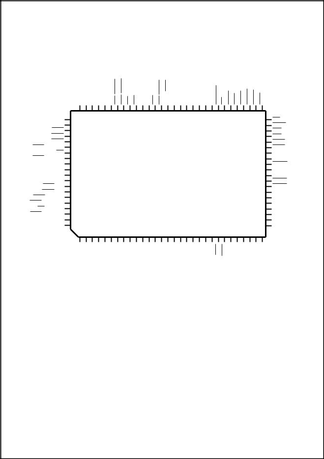
Signal/Pin Connection and Description
0.1 |
1.0 Signal/Pin Connection and Description |
|
|
|
|
|
|
|
||||||||||
Connection Signal/Pin |
|
|
|
|
|
|
|
|||||||||||
1.1 |
CONNECTION DIAGRAM |
|
|
|
|
|
|
|
|
|
|
|
|
|
|
|||
|
|
PD5 |
PD4 |
PD3 |
PD2 |
PD1 |
PD0 |
AFD/DSTRB |
SLIN/ASTRB |
INIT ERR PE SLCT ACK STB/WRITE BUSY/WAIT VSS P21 P20 MDAT MCLK KBDAT |
KBCLK |
DSKCHG WP |
INDEX TRK0 RDATA |
WGATE |
HDSEL |
STEP |
|
|
and |
|
PD6 |
80 79 78 77 76 75 74 73 72 71 70 69 68 67 66 65 64 63 62 61 60 59 58 57 56 55 54 53 52 51 |
|
||||||||||||||
|
81 |
|
|
|
|
|
|
|
|
|
|
|
|
|
50 |
DIR |
||
Description |
|
|
|
|
|
|
|
|
|
|
|
|
|
|
||||
|
PD7 |
82 |
|
|
|
|
|
|
|
|
|
|
|
|
|
49 |
WDATA |
|
|
CTS1 |
83 |
|
|
|
|
|
|
|
|
|
|
|
|
|
48 |
DR1/DENSEL |
|
|
DCD1 |
84 |
|
|
|
|
|
|
|
|
|
|
|
|
|
47 |
DR0 |
|
|
DSR1 |
85 |
|
|
|
|
|
|
|
|
|
|
|
|
|
46 |
MTR1/P12 |
|
|
BOUT1/DTR1/BADDR0 |
86 |
|
|
|
|
|
|
|
|
|
|
|
|
|
45 |
MTR0/DRATE0 |
|
|
RI1 |
87 |
|
|
|
|
|
|
|
|
|
|
|
|
|
44 |
IRTX/DENSEL |
|
|
RTS1/BADDR1 |
88 |
|
|
|
|
|
|
|
|
|
|
|
|
|
43 |
IRRX1/P12/DRATE0 |
|
|
SIN1 |
89 |
|
|
|
|
|
|
|
PC87309VLJ |
|
|
|
|
|
42 |
DACK3 |
|
|
|
VDD |
90 |
|
|
|
|
|
|
|
|
|
|
|
|
41 |
VDD |
|
|
|
VSS |
91 |
|
|
|
|
|
|
|
|
|
|
|
|
40 |
VSS |
|
|
|
SOUT1/CGF0 |
92 |
|
|
|
|
|
|
|
|
|
|
|
|
|
39 |
DACK2 |
|
|
CTS2/A11 |
93 |
|
|
|
|
|
|
|
|
|
|
|
|
|
38 |
DACK1 |
|
|
DCD2/P12 |
94 |
|
|
|
|
|
|
|
|
|
|
|
|
|
37 |
DRQ3 |
|
|
DSR2/DRATE0 |
95 |
|
|
|
|
|
|
|
|
|
|
|
|
|
36 |
DRQ2 |
|
BOUT2/DTR2/IRSL2/ID2 |
96 |
|
|
|
|
|
|
|
|
|
|
|
|
|
35 |
DRQ1 |
|
|
|
RI2/DENSEL |
97 |
|
|
|
|
|
|
|
|
|
|
|
|
|
34 |
MR |
|
|
RTS2/IRSL1/ID1 |
98 |
|
|
|
|
|
|
|
|
|
|
|
|
|
33 |
CLKIN |
|
|
SIN2/ID3 |
99 |
|
|
|
|
|
|
|
|
|
|
|
|
|
32 |
IRQ12 |
|
SOUT2/IRSL0/IRRX2/ID0 |
100 |
|
|
|
|
|
|
|
|
|
|
|
|
|
31 |
IRQ7 |
|
|
|
|
1 |
2 |
3 |
4 |
5 |
6 |
7 |
8 |
9 10 11 12 13 14 15 16 17 18 19 20 21 22 23 24 25 26 27 28 29 30 |
|
||||||
|
|
|
D0 |
D1 |
D2 |
D3 |
D4 |
D5 |
D6 |
D7 |
A0 A1 A2 A3 A4 A5 VSS A6 A7 A8 A9 A10 AEN |
IOCHRDY |
IORD IOWR |
TC IRQ1 IRQ3 |
IRQ4 |
IRQ5 |
IRQ6 |
|
|
www.national.com |
|
|
|
|
|
|
|
|
12 |
|
|
|
|
|
|
|
|

|
|
|
|
|
|
|
|
Signal/Pin Connection and Description |
||||||||||||||
|
1.2 SIGNAL/PIN DESCRIPTIONS |
|
|
The Module column indicates the functional module that is |
||||||||||||||||||
|
TABLE 1-1 lists the signals of the PC87309 in alphabetical |
associated with these pins. In this column, the System label |
||||||||||||||||||||
|
indicates internal functions that are common to more than |
|||||||||||||||||||||
|
order and shows the pin(s) associated with each. TABLE |
|||||||||||||||||||||
|
one module. The I/O and Group # column describes wheth- |
|||||||||||||||||||||
|
1-2 on page 18 lists the signals that are multiplexed in Full- |
|||||||||||||||||||||
|
er the pin is an input, output, or bidirectional pin (marked as |
|||||||||||||||||||||
|
IR and Two-UART modes. TABLE 1-3 on page 18 lists the |
|||||||||||||||||||||
|
Input, Output or I/O, respectively). |
|||||||||||||||||||||
|
pins that have strap functions during reset. |
|
||||||||||||||||||||
|
|
|
|
|
|
|
|
|
|
|
|
|
|
|
||||||||
|
|
|
|
|
|
|
TABLE 1-1. Signal/Pin Description Table |
|||||||||||||||
|
|
|
|
|
|
|
|
|
|
|
|
|
|
|
|
|
|
|
|
|||
|
|
Signal/Pin |
Pin |
Module |
I/O and |
|
|
|
|
|
|
Function |
|
|||||||||
|
|
Name |
Number |
Group # |
|
|
|
|
|
|
|
|||||||||||
|
|
|
|
|
|
|
|
|
|
|
|
|
|
|
|
|
||||||
|
|
|
|
|
|
|
|
|||||||||||||||
|
|
|
|
|
|
|
|
|||||||||||||||
|
|
A11-0 |
93, 20-16, |
ISA-Bus |
Input |
ISA-Bus Address –A11-0 are used for address decoding on any |
|
|||||||||||||||
|
|
|
|
|
|
14-9 |
|
Group 1 |
access except DMA accesses, on the condition that the AEN signal is |
|
||||||||||||
|
|
|
|
|
|
|
|
|
low. |
|
|
|
|
|
|
|
|
|
|
|
|
|
|
|
|
|
|
|
|
|
|
A11 is multiplexed with |
|
|
on pin 93 and available in Full-IR mode |
|
|||||||||
|
|
|
|
|
|
|
|
|
CTS2 |
|||||||||||||
|
|
|
|
|
|
|
|
|
only. Since A11 is required to support full ISA PnP mode (for |
|
||||||||||||
|
|
|
|
|
|
|
|
|
decoding A79h), this mode is not available in Two-UART mode. |
|
||||||||||||
|
|
|
|
|
|
|
|
|
See Section 2.2.2. |
|
||||||||||||
|
|
|
|
|
|
|
|
|
|
|
||||||||||||
|
|
|
|
|
|
68 |
Parallel Port |
Input |
Acknowledge –This input signal is pulsed low by the printer to |
|
||||||||||||
|
|
ACK |
||||||||||||||||||||
|
|
|
|
|
|
|
|
Group 3 |
indicate that it has received data from the parallel port. This pin is |
|
||||||||||||
|
|
|
|
|
|
|
|
|
internally connected to an internal weak pull-up. |
|
||||||||||||
|
|
|
|
|
74 |
Parallel Port |
I/O |
Automatic Feed –When this signal is low the printer should |
|
|||||||||||||
|
|
AFD |
||||||||||||||||||||
|
|
|
|
|
|
|
|
Group 8 |
automatically feed a line after printing each line. This pin is in TRI- |
|
||||||||||||
|
|
|
|
|
|
|
|
|
STATE after a 0 is loaded into the corresponding control register bit. |
|
||||||||||||
|
|
|
|
|
|
|
|
|
An external 4.7 KΩ pull-up resistor should be attached to this pin. |
|
||||||||||||
|
|
|
|
|
|
|
|
|
This signal is multiplexed with |
|
|
|
|
|
See TABLE 4-12 on page 101 |
|
||||||
|
|
|
|
|
|
|
|
|
DSTRB. |
|||||||||||||
|
|
|
|
|
|
|
|
|
for more information. |
|
||||||||||||
|
|
|
|
|
|
|
|
|||||||||||||||
|
|
AEN |
21 |
ISA-Bus |
Input |
DMA Address Enable –This input signal disables function selection |
|
|||||||||||||||
|
|
|
|
|
|
|
|
Group 1 |
via A11-0 when it is high. Access during DMA transfer is not affected |
|
||||||||||||
|
|
|
|
|
|
|
|
|
by this signal. This pin is used for external decoding of A11-15 in |
|
||||||||||||
|
|
|
|
|
|
|
|
|
Two-UART mode or A15-12 in Full-IR mode. |
|
||||||||||||
|
|
|
|
|
|
|
|
|
||||||||||||||
|
|
|
|
|
|
73 |
Parallel Port |
Output |
Address Strobe (EPP) –This signal is used in EPP mode as an |
|
||||||||||||
|
|
ASTRB |
||||||||||||||||||||
|
|
|
|
|
|
|
|
Group 8 |
address strobe. It is active low. |
|
||||||||||||
|
|
|
|
|
|
|
|
|
This signal is multiplexed with |
SLIN. |
|
See TABLE 4-12 on page 101 for |
|
|||||||||
|
|
|
|
|
|
|
|
|
more information. |
|
||||||||||||
|
|
|
|
|
|
|
||||||||||||||||
|
BADDR1,0 |
88,86 |
Configuration |
Input |
Base Address Strap Pins 0 and 1 –These pins determine the base |
|
||||||||||||||||
|
|
|
|
|
|
|
|
Group 4 |
addresses of the Index and Data registers, the value of the Plug and |
|
||||||||||||
|
|
|
|
|
|
|
|
|
Play ISA Serial Identifier and the configuration state immediately after |
|
||||||||||||
|
|
|
|
|
|
|
|
|
reset. These pins are pulled down by internal 30 KΩ resistors. |
|
||||||||||||
|
|
|
|
|
|
|
|
|
External 10 KΩ pull-up resistors to VDD should be employed. |
|
||||||||||||
|
|
|
|
|
|
|
|
|
BADDR1 is multiplexed with |
|
|
|
|
|
|
|||||||
|
|
|
|
|
|
|
|
|
RTS1. |
|||||||||||||
|
|
|
|
|
|
|
|
|
BADDR0 is multiplexed with |
|
|
|
and BOUT1. |
|
||||||||
|
|
|
|
|
|
|
|
|
DTR1 |
|||||||||||||
|
|
|
|
|
|
|
|
|
See TABLE 2-1 and Section 2.1. |
|
||||||||||||
|
|
|
|
|
|
|
||||||||||||||||
|
BOUT2,1 |
96,86 |
UART1, |
Output |
Baud Output –This multi-function pin provides the associated serial |
|
||||||||||||||||
|
|
|
|
|
|
|
UART2 |
Group 12 |
channel Baud Rate generator output signal if test mode is selected, |
|
||||||||||||
|
|
|
|
|
|
|
|
|
i.e., bit 7 of the EXCR1 register is set. See “Bit 7 - Baud Generator |
|
||||||||||||
|
|
|
|
|
|
|
|
|
Test (BTEST)” on page 121. |
|
||||||||||||
|
|
|
|
|
|
|
|
|
After Master Reset this pin provides the DTR function. |
|
||||||||||||
|
|
|
|
|
|
|
|
|
BOUT2 is multiplexed with DTR2, IRSL2 and ID2. |
|
||||||||||||
|
|
|
|
|
|
|
|
|
BOUT1 is multiplexed with DRT1 and BADDR0. |
|
||||||||||||
|
|
|
|
|
|
|
||||||||||||||||
|
BUSY |
66 |
Parallel Port |
Input |
Busy –This pin is set high by the printer when it cannot accept |
|
||||||||||||||||
|
|
|
|
|
|
|
|
Group 2 |
another character. It is internally connected to a weak pull-down |
|
||||||||||||
|
|
|
|
|
|
|
|
|
resistor. |
|
|
|
|
|
|
|
|
|
|
|
|
|
|
|
|
|
|
|
|
|
|
This signal is multiplexed with |
|
See TABLE 4-12 on page 101 for |
|
||||||||||
|
|
|
|
|
|
|
|
|
WAIT. |
|||||||||||||
|
|
|
|
|
|
|
|
|
more information. |
|
||||||||||||
|
|
|
|
|
|
|
|
|
|
|
|
|
|
|
|
|
|
|
|
|
|
|
|
|
|
|
|
|
|
|
|
|
|
|
|
|
|
|
|
|
|
|
|
|
|
DESCRIPTIONS SIGNAL/PIN
13 |
www.national.com |

SIGNAL/PIN |
|
|
|
|
|
|
|
|
|
|
|
|
|
|
Signal/Pin Connection and Description |
||||||||||||||||||||||
|
|
|
|
|
|
|
|
|
|
|
|
|
|
|
|
|
|
|
|
|
|
|
|
|
|
|
|
|
|
|
|
|
|
|
|
|
|
|
|
Signal/Pin |
Pin |
Module |
I/O and |
|
|
|
|
|
|
Function |
|
||||||||||||||||||||||||
|
|
|
|
|
|
|
|
|
|
||||||||||||||||||||||||||||
|
|
|
Name |
Number |
Group # |
|
|
|
|
|
|
|
|||||||||||||||||||||||||
|
|
|
|
|
|
|
|
|
|
|
|
|
|
|
|
|
|
|
|
|
|
|
|
|
|
||||||||||||
|
|
|
|
|
|
|
|
|
|||||||||||||||||||||||||||||
|
|
|
|
|
|
|
|
|
|||||||||||||||||||||||||||||
DESCRIPTIONS |
|
|
CFG0 |
92 |
Configuration |
Input |
This pin selects between Full-IR and Two-UART mode as the default |
|
|||||||||||||||||||||||||||||
|
|
|
|
|
|
|
|
|
|
|
|
|
|
Group 4 |
configuration upon power up. It is pulled down by internal 30 KΩ |
|
|||||||||||||||||||||
|
|
|
|
|
|
|
|
|
|
|
|
|
|
|
|
resistors. External 10 KΩ pull-up resistors to VDD should be |
|
||||||||||||||||||||
|
|
|
|
|
|
|
|
|
|
|
|
|
|
|
|
employed. |
|
||||||||||||||||||||
|
|
|
|
|
|
|
|
|
|
|
|
|
|
|
|
This signal is multiplexed with SOUT1. |
|
||||||||||||||||||||
|
|
|
|
|
|
|
|
|
|
|
|
|
|
|
|
See TABLE 2-1 and Section 2.1. |
|
||||||||||||||||||||
|
|
|
|
|
|
|
|
||||||||||||||||||||||||||||||
|
|
CLKIN |
33 |
Clock |
Input |
Clock In –A TTL or CMOS compatible 48 MHz clock. |
|
||||||||||||||||||||||||||||||
|
|
|
|
|
|
|
|
|
|
|
|
|
|
|
Group 1 |
|
|
|
|
|
|
|
|
|
|
|
|
|
|
|
|
|
|
|
|
|
|
|
|
|
|
|
|
|
|
|
|
|
|
|
|
|
|
|
|
||||||||||||||||||||
|
|
|
|
|
|
|
|
|
|
|
|
|
93,83 |
UART1, |
Input |
UART1 and UART2 Clear to Send –When low, these signals indicate |
|
||||||||||||||||||||
|
|
|
CTS2,1 |
||||||||||||||||||||||||||||||||||
|
|
|
|
|
|
|
|
|
|
|
|
|
|
UART2 |
Group 1 |
that the modem or other data transfer device is ready to exchange data. |
|
||||||||||||||||||||
|
|
|
|
|
|
|
|
|
|
|
|
|
|
|
|
|
CTS2 |
|
is multiplexed with A11, and available only in Two-UART mode. |
|
|||||||||||||||||
|
|
|
|
|
|
|
|
|
|||||||||||||||||||||||||||||
|
|
|
D7-0 |
8-1 |
ISA-Bus |
I/O |
ISA-Bus Data –Bidirectional data lines to the microprocessor. D0 is |
|
|||||||||||||||||||||||||||||
|
|
|
|
|
|
|
|
|
|
|
|
|
|
|
Group 5 |
the LSB and D7 is the MSB. These signals have 24 mA (sink) |
|
||||||||||||||||||||
|
|
|
|
|
|
|
|
|
|
|
|
|
|
|
|
buffered outputs. |
|
||||||||||||||||||||
|
|
|
|
|
|
|
|
|
|
|
|
42 |
ISA-Bus |
Input |
|
DMA Acknowledge 1,2 and 3 –These active low input signals |
|
||||||||||||||||||||
|
|
|
DACK3 |
|
|||||||||||||||||||||||||||||||||
|
|
|
|
|
|
|
|
|
|
|
39,38 |
|
Group 1 |
|
acknowledge a request for DMA services and enable the IOWR and |
|
|||||||||||||||||||||
|
|
|
DACK2,1 |
|
|
||||||||||||||||||||||||||||||||
|
|
|
|
|
|
|
|
|
|
|
|
|
|
|
|
|
IORD input signals during a DMA transfer. These DMA signals can be |
|
|||||||||||||||||||
|
|
|
|
|
|
|
|
|
|
|
|
|
|
|
|
|
mapped to the following logical devices: FDC, UART or Parallel Port. |
|
|||||||||||||||||||
|
|
|
|
|
|
|
|
|
|
|
|
|
|
|
|||||||||||||||||||||||
|
|
|
|
|
|
|
|
|
|
|
|
94,84 |
UART1, |
Input |
UART1 and UART2 Data Carrier Detected –When low, this signal |
|
|||||||||||||||||||||
|
|
|
DCD2,1 |
||||||||||||||||||||||||||||||||||
|
|
|
|
|
|
|
|
|
|
|
|
|
|
UART2 |
Group 1 |
indicates that the modem or other data transfer device has detected |
|
||||||||||||||||||||
|
|
|
|
|
|
|
|
|
|
|
|
|
|
|
|
the data carrier. |
|
||||||||||||||||||||
|
|
|
|
|
|
|
|
|
|
|
|
|
|
|
|
|
|
|
|
is multiplexed with P12 and available only in Two-UART mode. |
|
||||||||||||||||
|
|
|
|
|
|
|
|
|
|
|
|
|
|
|
|
|
DCD2 |
||||||||||||||||||||
|
|
|
|
|
|
|
|
|
|||||||||||||||||||||||||||||
|
|
|
DENSEL |
97, 48 or |
FDC |
Output |
Density Select –Indicates that a high FDC density data rate (500 |
|
|||||||||||||||||||||||||||||
|
|
|
|
|
|
|
|
|
|
|
|
|
44 |
|
Group 11 |
Kbps or 1 Mbps) or a low density data rate (250 or 300 Kbps) is |
|
||||||||||||||||||||
|
|
|
|
|
|
|
|
|
|
|
|
|
|
|
|
selected. |
|
||||||||||||||||||||
|
|
|
|
|
|
|
|
|
|
|
|
|
|
|
|
DENSEL polarity is controlled by bit 5 of the SuperI/O FDC |
|
||||||||||||||||||||
|
|
|
|
|
|
|
|
|
|
|
|
|
|
|
|
Configuration register as described in Section 2.5.1. |
|
||||||||||||||||||||
|
|
|
|
|
|
|
|
|
|
|
|
|
|
|
|
This signal is multiplexed with: IRTX, , |
|
|
|
|
or |
|
|
|
|
|
|
|
|
|
|||||||
|
|
|
|
|
|
|
|
|
|
|
|
|
|
|
|
DR1, |
R12. |
||||||||||||||||||||
|
|
|
|
|
|
|
|
|
50 |
FDC |
Output |
Direction –This output signal determines the direction of the Floppy |
|
||||||||||||||||||||||||
|
|
|
DIR |
||||||||||||||||||||||||||||||||||
|
|
|
|
|
|
|
|
|
|
|
|
|
|
|
Group 11 |
Disk Drive (FDD) head movement (active = step in, inactive = step |
|
||||||||||||||||||||
|
|
|
|
|
|
|
|
|
|
|
|
|
|
|
|
out) during a seek operation. During reads or writes, DIR is inactive. |
|
||||||||||||||||||||
|
|
|
|
|
|
|
|
|
|
|
|
|
48, 47 |
FDC |
Output |
|
Drive Select 0 and 1 –These active low output signals are the |
|
|||||||||||||||||||
|
|
|
DR1,0 |
|
|||||||||||||||||||||||||||||||||
|
|
|
|
|
|
|
|
|
|
|
|
|
|
|
Group 11 |
|
decoded drive select output signals. |
DR0 |
and DR1 are controlled by |
|
|||||||||||||||||
|
|
|
|
|
|
|
|
|
|
|
|
|
|
|
|
|
Digital Output Register (DOR) bits 0 and 1. They are encoded with |
|
|||||||||||||||||||
|
|
|
|
|
|
|
|
|
|
|
|
|
|
|
|
|
information to control four FDDs when bit 7 of the SuperI/O FDC |
|
|||||||||||||||||||
|
|
|
|
|
|
|
|
|
|
|
|
|
|
|
|
|
Configuration register is 1, as described in Section 2.5.1. |
|
|||||||||||||||||||
|
|
|
|
|
|
|
|
|
|
|
|
|
|
|
|
|
|
|
can optionally become a logical OR of |
|
|
and |
|
|
when |
|
|||||||||||
|
|
|
|
|
|
|
|
|
|
|
|
|
|
|
|
|
DR0 |
DR0 |
MTR0 |
||||||||||||||||||
|
|
|
|
|
|
|
|
|
|
|
|
|
|
|
|
|
MTR0/DRATE0 is used as DRATE0. |
|
|||||||||||||||||||
|
|
|
|
|
|
|
|
|
|
|
|
|
|
|
|
|
|
|
is multiplexed with DENSEL and is available only in Two-UART |
|
|||||||||||||||||
|
|
|
|
|
|
|
|
|
|
|
|
|
|
|
|
|
DR1 |
||||||||||||||||||||
|
|
|
|
|
|
|
|
|
|
|
|
|
|
|
|
|
mode. Optionally, it can become a logical OR of DR1 and MTR1 |
|
|||||||||||||||||||
|
|
|
|
|
|
|
|
|
|
|
|
|
|
|
|
when MTR1/P12 is used as P12. |
|
||||||||||||||||||||
|
|
|
|
|
|
|
|
|
|
|
|
|
|
|
|
|
See |
|
for more information. |
|
|||||||||||||||||
|
|
|
|
|
|
|
|
|
|
|
|
|
|
|
|
|
MTR0,1 |
||||||||||||||||||||
|
|
|
DRATE0 |
95, 45 or |
FDC |
Output |
Data Rate 0 –This output signal reflects the value of bit 0 of the |
|
|||||||||||||||||||||||||||||
|
|
|
|
|
|
|
|
|
|
|
|
|
43 |
|
Group 14 |
Configuration Control Register (CCR) or the Data Rate Select Register |
|
||||||||||||||||||||
|
|
|
|
|
|
|
|
|
|
|
|
|
|
|
|
(DSR), whichever was written to last. Output from the pin is totem-pole |
|
||||||||||||||||||||
|
|
|
|
|
|
|
|
|
|
|
|
|
|
|
|
buffered (6 mA sink, 6 mA source). |
|
||||||||||||||||||||
|
|
|
|
|
|
|
|
|
|
|
|
|
|
|
|
This signal is multiplexed with IRRX1/P12, |
|
or |
|
|
|
||||||||||||||||
|
|
|
|
|
|
|
|
|
|
|
|
|
|
|
|
MTR0 |
DSR2 |
||||||||||||||||||||
|
|
|
|
|
|
|
|
|
|||||||||||||||||||||||||||||
|
|
|
DRQ3-1 |
37-35 |
ISA-Bus |
Output |
DMA Request 1, 2 and 3 –These active high output signals inform |
|
|||||||||||||||||||||||||||||
|
|
|
|
|
|
|
|
|
|
|
|
|
|
|
Group 13 |
the DMA controller that a data transfer is needed. These DMA signals |
|
||||||||||||||||||||
|
|
|
|
|
|
|
|
|
|
|
|
|
|
|
|
can be mapped to the following logical devices: Floppy Disk Controller |
|
||||||||||||||||||||
|
|
|
|
|
|
|
|
|
|
|
|
|
|
|
|
(FDC), UART or parallel port. |
|
||||||||||||||||||||
|
|
|
|
|
|
|
|
|
|
||||||||||||||||||||||||||||
|
|
|
|
|
|
|
|
|
|
|
|
|
58 |
FDC |
Input |
Disk Change –This input signal indicates whether or not the drive |
|
||||||||||||||||||||
|
|
|
DSKCHG |
||||||||||||||||||||||||||||||||||
|
|
|
|
|
|
|
|
|
|
|
|
|
|
|
Group 1 |
door has been opened. The state of this pin is available from the |
|
||||||||||||||||||||
|
|
|
|
|
|
|
|
|
|
|
|
|
|
|
|
Digital Input Register (DIR). This pin can also be configured as the |
|
||||||||||||||||||||
|
|
|
|
|
|
|
|
|
|
|
|
|
|
|
|
RGATE data separator diagnostic input signal via the MODE |
|
||||||||||||||||||||
|
|
|
|
|
|
|
|
|
|
|
|
|
|
|
|
command. See the MODE command in Section 3.7.7. |
|
||||||||||||||||||||
|
|
|
|
|
|
|
|
|
|
|
|
|
|
|
|
|
|
|
|
|
|
|
|
|
|
|
|
|
|
|
|
|
|
|
|
|
|
|
|
|
|
|
|
|
|
|
|
|
|
|
|
|
|
|
|
|
|
|
|
|
|
|
|
|
|
|
|
|
|
|
|
|
|
|
|
www.national.com |
14 |

|
|
|
|
|
|
|
|
|
|
|
|
|
|
Signal/Pin Connection and Description |
SIGNAL/PIN |
||||||||||||||||
|
|
|
|
|
|
|
|
|
|
|
|
|
|
|
|
|
|
|
|
|
|
|
|
|
|
|
|
|
|
|
|
|
|
Signal/Pin |
Pin |
Module |
I/O and |
|
|
|
|
|
|
|
|
|
|
|
Function |
|
|||||||||||||
|
|
|
|
|
|
|
|
|
|
|
|
|
|
|
|||||||||||||||||
|
|
Name |
Number |
Group # |
|
|
|
|
|
|
|
|
|
|
|
|
|
||||||||||||||
|
|
|
|
|
|
|
|
|
|
|
|
|
|
|
|
|
|
|
|
||||||||||||
|
|
|
|
|
|
|
|
|
|
|
|
|
|
|
|
|
|
||||||||||||||
|
|
|
|
|
|
|
|
|
|
|
|
|
|
|
|
|
|
||||||||||||||
|
|
|
|
|
|
|
|
|
|
|
|
95,85 |
UART1, |
Input |
Data Set Ready –When low, this signal indicates that the data |
|
|
||||||||||||||
|
|
DSR2,1 |
DESCRIPTIONS |
||||||||||||||||||||||||||||
|
|
|
|
|
|
|
|
|
|
|
|
|
UART2 |
Group 1 |
transfer device, e.g., modem, is ready to establish a communications |
|
|||||||||||||||
|
|
|
|
|
|
|
|
|
|
|
|
|
|
|
link. |
|
|
||||||||||||||
|
|
|
|
|
|
|
|
|
|
|
|
|
|
|
|
|
|
is multiplexed with DRATE0 and available only in Two-UART |
|
|
|||||||||||
|
|
|
|
|
|
|
|
|
|
|
|
|
|
|
|
DSR2 |
|
||||||||||||||
|
|
|
|
|
|
|
|
|
|
|
|
|
|
|
|
mode. |
|
|
|||||||||||||
|
|
|
|
|
|
|
|
|
|
|
|
|
|
|
|
|
|||||||||||||||
|
|
|
|
|
|
|
|
|
|
|
74 |
Parallel Port |
Output |
Data Strobe –This signal is used in EPP mode as a data strobe. It |
|
|
|||||||||||||||
|
|
DSTRB |
|
||||||||||||||||||||||||||||
|
|
|
|
|
|
|
|
|
|
|
|
|
|
Group 8 |
is active low. |
|
|
||||||||||||||
|
|
|
|
|
|
|
|
|
|
|
|
|
|
|
|
DSTRB |
is multiplexed with |
AFD. |
|
See TABLE 4-12 on page 101 for |
|
|
|||||||||
|
|
|
|
|
|
|
|
|
|
|
|
|
|
|
|
more information. |
|
|
|||||||||||||
|
|
|
|
|
|
|
|
|
|
|
|
|
|
|
|
||||||||||||||||
|
|
|
|
|
|
|
|
|
|
|
96,86 |
UART1, |
Output |
Data Terminal Ready –When low, this output signal indicates to the |
|
|
|||||||||||||||
|
|
DTR2,1 |
|
||||||||||||||||||||||||||||
|
|
|
|
|
|
|
|
|
|
|
|
|
UART2 |
Group 12 |
modem or other data transfer device that the UART1 or UART2 is |
|
|
||||||||||||||
|
|
|
|
|
|
|
|
|
|
|
|
|
|
|
ready to establish a communications link. |
|
|
||||||||||||||
|
|
|
|
|
|
|
|
|
|
|
|
|
|
|
A Master Reset (MR) deactivates this signal high, and loopback |
|
|
||||||||||||||
|
|
|
|
|
|
|
|
|
|
|
|
|
|
|
operation holds this signal inactive. |
|
|
||||||||||||||
|
|
|
|
|
|
|
|
|
|
|
|
|
|
|
|
|
is multiplexed with BADDR0 and with BOUT1. |
|
|
||||||||||||
|
|
|
|
|
|
|
|
|
|
|
|
|
|
|
|
DTR1 |
|
||||||||||||||
|
|
|
|
|
|
|
|
|
|
|
|
|
|
|
|
|
is multiplexed with IRSL2/ID2/BOUT2 and is available only in |
|
|
||||||||||||
|
|
|
|
|
|
|
|
|
|
|
|
|
|
|
|
DTR2 |
|
||||||||||||||
|
|
|
|
|
|
|
|
|
|
|
|
|
|
|
|
Two-UART mode. (BOUT2 is multiplexed implicitly and controlled by |
|
|
|||||||||||||
|
|
|
|
|
|
|
|
|
|
|
|
|
|
|
|
UART2.) |
|
|
|||||||||||||
|
|
|
|
|
|
|
|
|
|
|
|
|
|
|
|||||||||||||||||
|
|
|
|
|
|
|
|
|
71 |
Parallel Port |
Input |
Error –This input signal is set active low by the printer when it has |
|
|
|||||||||||||||||
|
|
ERR |
|
||||||||||||||||||||||||||||
|
|
|
|
|
|
|
|
|
|
|
|
|
|
Group 3 |
detected an error. This pin is internally connected to an internal weak |
|
|
||||||||||||||
|
|
|
|
|
|
|
|
|
|
|
|
|
|
|
pull-up. |
|
|
||||||||||||||
|
|
|
|
|
|
|
|
|
52 |
FDC |
Output |
Head Select –This output signal determines which side of the FDD |
|
|
|||||||||||||||||
|
|
HDSEL |
|
||||||||||||||||||||||||||||
|
|
|
|
|
|
|
|
|
|
|
|
|
|
Group 11 |
is accessed. Active low selects side 1, inactive selects side 0. |
|
|
||||||||||||||
|
|
|
|
|
|
|
|
||||||||||||||||||||||||
|
ID3 |
99 |
UART2 |
Input |
Identification – These ID signals identify the infrared transceiver for |
|
|
||||||||||||||||||||||||
|
ID2 |
96 |
|
Group 1 |
Plug and Play support. These pins are read after reset. |
|
|
||||||||||||||||||||||||
|
ID1 |
98 |
|
|
ID0,1,2 are multiplexed implicitly with IRSL0,1,2 respectively by the |
|
|
||||||||||||||||||||||||
|
|
|
UART2 cell. |
|
|
||||||||||||||||||||||||||
|
ID0 |
100 |
|
|
|
|
|||||||||||||||||||||||||
|
|
|
ID3 is multiplexed with SIN2. |
|
|
||||||||||||||||||||||||||
|
|
|
|
|
|
|
|
|
|
|
|
|
|
|
|
|
|||||||||||||||
|
|
|
|
|
|
|
|
|
|
|
|
|
|
|
ID2 is multiplexed with BOUT2, |
|
IRSL2. |
|
|
||||||||||||
|
|
|
|
|
|
|
|
|
|
|
|
|
|
|
DTR2, |
|
|||||||||||||||
|
|
|
|
|
|
|
|
|
|
|
|
|
|
|
|
ID1 is multiplexed with |
|
|
|
IRSL1 |
|
|
|||||||||
|
|
|
|
|
|
|
|
|
|
|
|
|
|
|
|
RTS2, |
|
||||||||||||||
|
|
|
|
|
|
|
|
|
|
|
|
|
|
|
|
ID0 is multiplexed with SOUT2,IRSL0, IRRX2 |
|
|
|||||||||||||
|
|
|
|
|
|
|
|
|
|
|
|
|
|||||||||||||||||||
|
|
|
|
|
|
|
|
56 |
FDC |
Input |
Index –This input signal indicates the beginning of an FDD track. |
|
|
||||||||||||||||||
|
|
INDEX |
|
||||||||||||||||||||||||||||
|
|
|
|
|
|
|
|
|
|
|
|
|
|
Group 1 |
|
|
|
|
|
|
|
|
|
|
|
|
|
|
|
|
|
|
|
|
|
|
|
|
|
|
|
|
|
||||||||||||||||||||
|
|
|
|
|
|
72 |
Parallel Port |
I/O |
Initialize –When this signal is active low, it causes the printer to be |
|
|
||||||||||||||||||||
|
|
INIT |
|
||||||||||||||||||||||||||||
|
|
|
|
|
|
|
|
|
|
|
|
|
|
Group 8 |
initialized. This signal is in TRI-STATE after a 1 is loaded into the |
|
|
||||||||||||||
|
|
|
|
|
|
|
|
|
|
|
|
|
|
|
corresponding control register bit. |
|
|
||||||||||||||
|
|
|
|
|
|
|
|
|
|
|
|
|
|
|
An external 4.7 KΩ pull-up resistor should be employed. |
|
|
||||||||||||||
|
|
|
|
|
|
|
|
|
|||||||||||||||||||||||
|
|
IOCHRDY |
22 |
ISA-Bus |
Output |
I/O Channel Ready –This is the I/O channel ready open drain output |
|
|
|||||||||||||||||||||||
|
|
|
|
|
|
|
|
|
|
|
|
|
|
Group 15 |
signal. When IOCHRDY is driven low, the EPP extends the host cycle. |
|
|
||||||||||||||
|
|
|
|
|
|
|
|
|
|
|
|
|
|||||||||||||||||||
|
|
|
|
|
|
|
23 |
ISA-Bus |
Input |
I/O Read –An active low |
|
|
|
input signal indicates that the |
|
|
|||||||||||||||
|
|
IORD |
RD |
|
|||||||||||||||||||||||||||
|
|
|
|
|
|
|
|
|
|
|
|
|
|
Group 1 |
|
microprocessor has read data. |
|
|
|||||||||||||
|
|
|
|
|
|
|
|
|
|
|
|
|
|||||||||||||||||||
|
|
|
|
|
|
|
24 |
ISA-Bus |
Input |
|
I/O Write – |
|
is an active low input signal that indicates a write |
|
|
||||||||||||||||
|
|
IOWR |
|
WR |
|
||||||||||||||||||||||||||
|
|
|
|
|
|
|
|
|
|
|
|
|
|
Group 1 |
|
operation from the microprocessor to the controller. |
|
|
|||||||||||||
|
|
|
|
|
|
|
|
|
|
||||||||||||||||||||||
|
|
IRQ1 |
26 |
ISA-Bus |
I/O |
|
Interrupt Requests 1, 3, 4, 5, 6, 7 and 12 –IRQ polarity and push- |
|
|
||||||||||||||||||||||
|
|
IRQ7-3 |
31-27 |
|
Group 10 |
|
pull or open-drain output selection is software configurable by the |
|
|
||||||||||||||||||||||
|
|
IRQ12 |
32 |
|
|
|
logical device mapped to the IRQ line. |
|
|
||||||||||||||||||||||
|
|
|
|
|
Keyboard Controller (KBC) or Mouse interrupts can be configured by |
|
|
||||||||||||||||||||||||
|
|
|
|
|
|
|
|
|
|
|
|
|
|
|
|
|
|
||||||||||||||
|
|
|
|
|
|
|
|
|
|
|
|
|
|
|
|
the Interrupt Request Type Select 0 register (index 71h) as either |
|
|
|||||||||||||
|
|
|
|
|
|
|
|
|
|
|
|
|
|
|
|
edge or level. |
|
|
|||||||||||||
|
|
|
|
|
|
|
|
|
|||||||||||||||||||||||
|
|
IRRX2,1 |
100,43 |
UART2 |
Input |
Infrared Reception 1 and 2 –Infrared serial input data. |
|
|
|||||||||||||||||||||||
|
|
|
|
|
|
|
|
|
|
|
|
|
|
Group 18 |
IRRX1 is multiplexed with P12/DRATE0 and is available only in Two- |
|
|
||||||||||||||
|
|
|
|
|
|
|
|
|
|
|
|
|
|
|
UART mode. |
|
|
||||||||||||||
|
|
|
|
|
|
|
|
|
|
|
|
|
|
|
IRRX2 is multiplexed with SOUT2/IRSL0/ID0 and is available only in |
|
|
||||||||||||||
|
|
|
|
|
|
|
|
|
|
|
|
|
|
|
Full-IR mode. |
|
|
||||||||||||||
|
|
|
|
|
|
|
|
|
|
|
|
|
|
|
|
|
|
|
|
|
|
|
|
|
|
|
|
|
|
|
|
|
|
|
|
|
|
|
|
|
|
|
|
|
|
|
|
|
|
|
|
|
|
|
|
|
|
|
|
|
|
|
|
15 |
www.national.com |

SIGNAL/PIN |
|
|
|
|
|
|
|
Signal/Pin Connection and Description |
|||||||
|
|
|
|
|
|
|
|
|
|
|
|
|
|
|
|
|
|
Signal/Pin |
Pin |
Module |
I/O and |
|
|
Function |
|
||||||
|
|
|
|
|
|
||||||||||
|
|
|
Name |
Number |
Group # |
|
|
|
|||||||
|
|
|
|
|
|
|
|
|
|
|
|||||
|
|
|
|
|
|
|
|
|
|
||||||
|
|
|
|
|
|
|
|
|
|
||||||
DESCRIPTIONS |
|
|
IRSL0 |
100 |
UART2 |
Output |
|
Infrared Control Signals 0, 1 and 2 –These signals control the |
|
||||||
|
|
IRSL1 |
98 |
|
Group 12 |
|
Infrared analog front end. The pins on which these signals are driven |
|
|||||||
|
|
|
IRSL2 |
96 |
|
|
|
is determined by the SuperI/O Configuration 2 register (index 22h). |
|
||||||
|
|
|
|
|
|
SeeTABLE 1-2 for more information. |
|
||||||||
|
|
|
|
|
|
|
|
|
|
|
|||||
|
|
|
|
|
|
|
|
|
|
IRSL0 is multiplexed on pin 100 with SOUT2, IRRX2 and ID0, and is |
|
||||
|
|
|
|
|
|
|
|
|
|
available only in Full-IR mode. |
|
||||
|
|
|
|
|
|
|
|
|
|
IRSL1 is multiplexed on pin 98 with |
|
|
and ID1, and is available |
|
|
|
|
|
|
|
|
|
|
|
RTS2 |
||||||
|
|
|
|
|
|
|
|
|
only in Full-IR mode. |
|
|||||
|
|
|
|
|
|
|
|
|
IRSL2 is multiplexed on pin 96 with |
|
BOUT2 and ID2, and is |
|
|||
|
|
|
|
|
|
|
|
|
DTR2, |
||||||
|
|
|
|
|
|
|
|
|
|
available only in Full-IR mode. |
|
||||
|
|
|
|
|
|
|
|
|
|||||||
|
|
|
IRTX |
44 |
UART2 |
Output |
Infrared Transmit –Infrared serial output data. |
|
|||||||
|
|
|
|
|
|
|
|
Group 12 |
This signal is multiplexed with DENSEL only in Two-UART mode. |
|
|||||
|
|
|
|
|
|
|
|
||||||||
|
|
KBCLK |
59 |
KBC |
I/O |
Keyboard Clock –This I/O pin transfers the keyboard clock between |
|
||||||||
|
|
|
|
|
|
|
|
Group 6 |
the SuperI/O chip and the external keyboard using the PS/2 protocol. |
|
|||||
|
|
|
|
|
|
|
|
|
This pin is connected internally to the internal TO signal of the KBC. |
|
|||||
|
|
|
|
|
|
|
|
||||||||
|
|
KBDAT |
60 |
KBC |
I/O |
Keyboard Data –This I/O pin transfers the keyboard data between |
|
||||||||
|
|
|
|
|
|
|
|
Group 6 |
the SuperI/O chip and the external keyboard using the PS/2 protocol. |
|
|||||
|
|
|
|
|
|
|
|
|
This pin is connected internally to KBC’s P10. |
|
|||||
|
|
|
|
|
|
|
|
||||||||
|
|
MCLK |
61 |
KBC |
I/O |
Mouse Clock –This I/O pin transfers the mouse clock between the |
|
||||||||
|
|
|
|
|
|
|
|
Group 6 |
SuperI/O chip and the external keyboard using the PS/2 protocol. |
|
|||||
|
|
|
|
|
|
|
|
|
This pin is connected internally to KBC’s T1. |
|
|||||
|
|
|
|
|
|
|
|
||||||||
|
|
MDAT |
62 |
KBC |
I/O |
Mouse Data –This I/O pin transfers the mouse data between the |
|
||||||||
|
|
|
|
|
|
|
|
Group 6 |
SuperI/O chip and the external keyboard using the PS/2 protocol. |
|
|||||
|
|
|
|
|
|
|
|
|
This pin is connected internally to KBC’s P11. |
|
|||||
|
|
|
|
|
|
|
|
||||||||
|
|
MR |
34 |
ISA-Bus |
Input |
Master Reset –An active high MR input signal resets the controller |
|
||||||||
|
|
|
|
|
|
|
|
Group 1 |
to the idle state, and resets all disk interface output signals to their |
|
|||||
|
|
|
|
|
|
|
|
|
inactive states. MR also clears the DOR, DSR and CCR registers, |
|
|||||
|
|
|
|
|
|
|
|
|
and resets the MODE command, CONFIGURE command, and LOCK |
|
|||||
|
|
|
|
|
|
|
|
|
command parameters to their default values. MR does not affect the |
|
|||||
|
|
|
|
|
|
|
|
|
SPECIFY command parameters. MR sets the configuration registers |
|
|||||
|
|
|
|
|
|
|
|
|
to their selected default values. |
|
|||||
|
|
|
|
|
|
|
|
|
|
|
|||||
|
|
|
|
|
|
46,45 |
FDC |
Output |
Motor Select 1,0 –These motor enable lines for drives 0 and 1 are |
|
|||||
|
|
|
MTR1,0 |
||||||||||||
|
|
|
|
|
|
|
|
Group 11 |
controlled by bits D7-4 of the Digital Output Register (DOR). They are |
|
|||||
|
|
|
|
|
|
|
|
|
output signals that are active when they are low. They are encoded with |
|
|||||
|
|
|
|
|
|
|
|
|
information to control four FDDs when bit 7 of the SuperI/O FDC |
|
|||||
|
|
|
|
|
|
|
|
|
Configuration register is set See TABLE 1-2 for more information. See |
|
|||||
|
|
|
|
|
|
|
|
|
|
DR1,0. |
|
||||
|
|
|
|
|
|
|
|
|
|
|
is multiplexed with DRATE0 only in Two-UART mode. |
|
|||
|
|
|
|
|
|
|
|
|
|
MTR0 |
|||||
|
|
|
|
|
|
|
|
|
|
|
is multiplexed with P12 only in Two-UART mode. |
|
|||
|
|
|
|
|
|
|
|
|
|
MTR1 |
|||||
|
|
|
|
|
|
|
|
|
|||||||
|
|
|
P12 |
94, 46 or |
KBC |
I/O |
I/O Port –KBC quasi-bidirectional port for general purpose input and |
|
|||||||
|
|
|
|
|
|
43 |
|
Group 7 |
output. |
|
|||||
|
|
|
|
|
|
|
|
|
P12 is multiplexed on pin 43 with IRRX1 and DRATE0, on pin 46 with |
|
|||||
|
|
|
|
|
|
|
|
|
|
MTR1, and on pin 94 with DCD2. |
|
||||
|
|
|
|
|
|
|
|
|
|||||||
|
|
|
P21,P20 |
64,63 |
KBC |
I/O |
I/O Port –KBC open-drain signals for general purpose input and |
|
|||||||
|
|
|
|
|
|
|
|
Group 7 |
output. These signals are controlled by KBC firmware. |
|
|||||
|
|
|
|
|
|
|
|
||||||||
|
|
PD7-0 |
82-75 |
Parallel Port |
I/O |
Parallel Port Data –These bidirectional signals transfer data to and |
|
||||||||
|
|
|
|
|
|
|
|
Group 9 |
from the peripheral data bus and the appropriate parallel port data |
|
|||||
|
|
|
|
|
|
|
|
|
register. These signals have a high current drive capability. See |
|
|||||
|
|
|
|
|
|
|
|
|
Section 10.1. |
|
|||||
|
|
|
|
|
|
|
|
||||||||
|
|
PE |
70 |
Parallel Port |
Input |
Paper End –This input signal is set high by the printer when it is out |
|
||||||||
|
|
|
|
|
|
|
|
Group 2 |
of paper. This pin has an internal weak pull-up or pull-down resistor. |
|
|||||
|
|
|
|
|
|
|
|
Group 3 |
|
|
|
|
|
|
|
|
|
|
|
|
|
|
|
|
|
||||||
|
|
|
|
|
54 |
FDC |
Input |
Read Data –This input signal holds raw serial data read from the |
|
||||||
|
|
|
RDATA |
||||||||||||
|
|
|
|
|
|
|
|
Group 1 |
Floppy Disk Drive (FDD). |
|
|||||
|
|
|
|
|
|
|
|
|
|
|
|
|
|
|
|
|
|
|
|
|
|
|
|
|
|
|
|
|
|
|
|
www.national.com |
16 |

|
|
|
|
|
|
|
|
|
|
|
|
Signal/Pin Connection and Description |
SIGNAL/PIN |
|||||||||||||
|
|
|
|
|
|
|
|
|
|
|
|
|
|
|
|
|
|
|
|
|
|
|
|
|
|
|
|
|
Signal/Pin |
Pin |
Module |
I/O and |
|
|
|
|
|
|
|
Function |
|
||||||||||||
|
|
|
|
|
|
|
|
|
|
|
||||||||||||||||
|
|
Name |
Number |
Group # |
|
|
|
|
|
|
|
|
|
|||||||||||||
|
|
|
|
|
|
|
|
|
|
|
|
|
|
|
|
|
||||||||||
|
|
|
|
|
|
|
|
|
|
|
|
|
|
|
|
|||||||||||
|
|
|
|
|
|
|
|
|
|
|
|
|
|
|
|
|||||||||||
|
|
|
|
|
|
|
|
|
|
97,87 |
UART1 |
Input |
Ring Indicators (Modem) –When low, this signal indicates that a |
|
|
|||||||||||
|
|
RI2,1 |
DESCRIPTIONS |
|||||||||||||||||||||||
|
|
|
|
|
|
|
|
|
|
|
|
Group 1 |
telephone ring signal has been received by the modem. |
|
||||||||||||
|
|
|
|
|
|
|
|
|
|
|
|
|
|
|||||||||||||
|
|
|
|
|
|
|
|
|
|
|
|
|
The |
RI1 |
and |
RI2 |
pins have schmitt-trigger input buffers. |
|
|
|||||||
|
|
|
|
|
|
|
|
|
|
|
|
|
|
RI2 is multiplexed with DENSEL and available only in Two-UART |
|
|
||||||||||
|
|
|
|
|
|
|
|
|
|
|
|
|
|
mode. |
|
|
||||||||||
|
|
|
|
|
|
|
|
|
|
|
|
|
|
|
||||||||||||
|
|
|
|
|
|
|
|
|
|
98,88 |
UART1, |
Output |
Request to Send –When low, these output signals indicate to the |
|
|
|||||||||||
|
|
RTS2,1 |
|
|||||||||||||||||||||||
|
|
|
|
|
|
|
|
|
|
|
UART2 |
Group 12 |
modem or other data transfer device that the corresponding UART1 |
|
|
|||||||||||
|
|
|
|
|
|
|
|
|
|
|
|
|
or UART2 is ready to exchange data. |
|
|
|||||||||||
|
|
|
|
|
|
|
|
|
|
|
|
|
A Master Reset (MR) sets |
|
|
to inactive high. Loopback operation |
|
|
||||||||
|
|
|
|
|
|
|
|
|
|
|
|
|
RTS |
|
||||||||||||
|
|
|
|
|
|
|
|
|
|
|
|
|
|
holds it inactive. |
|
|
||||||||||
|
|
|
|
|
|
|
|
|
|
|
|
|
|
|
is multiplexed on pin 98 with IRSL1 and ID1, and available only |
|
|
|||||||||
|
|
|
|
|
|
|
|
|
|
|
|
|
|
RTS2 |
|
|||||||||||
|
|
|
|
|
|
|
|
|
|
|
|
|
|
in Two-UART mode. RTS1 is multiplexed on pin 88 with BADDR1. |
|
|
||||||||||
|
|
|
|
|
|
|
|
|
||||||||||||||||||
|
|
SIN2,1 |
99,89 |
UART1, |
Input |
Serial Input –This input signal receives composite serial data from |
|
|
||||||||||||||||||
|
|
|
|
|
|
|
|
|
|
|
UART2 |
Group 1 |
the communications link (peripheral device, modem or other data |
|
|
|||||||||||
|
|
|
|
|
|
|
|
|
|
|
|
|
transfer device). |
|
|
|||||||||||
|
|
|
|
|
|
|
|
|
|
|
|
|
SIN2 is multiplexed on pin 99 with ID3 and available only in Two- |
|
|
|||||||||||
|
|
|
|
|
|
|
|
|
|
|
|
|
UART mode. |
|
|
|||||||||||
|
|
|
|
|
|
|
|
|||||||||||||||||||
|
SLCT |
69 |
Parallel Port |
Input |
Select –This input signal is set active high by the printer when the |
|
|
|||||||||||||||||||
|
|
|
|
|
|
|
|
|
|
|
|
Group 2 |
printer is selected. This pin is internally connected to a nominal 25 KΩ |
|
|
|||||||||||
|
|
|
|
|
|
|
|
|
|
|
|
|
pull-down resistor. |
|
|
|||||||||||
|
|
|
|
|
|
|
|
73 |
Parallel Port |
I/O |
Select Input –When this signal is active low it selects the printer. |
|
|
|||||||||||||
|
|
SLIN |
|
|||||||||||||||||||||||
|
|
|
|
|
|
|
|
|
|
|
|
Group 8 |
This signal is in TRI-STATE after a 0 is loaded into the corresponding |
|
|
|||||||||||
|
|
|
|
|
|
|
|
|
|
|
|
|
control register bit. Use an external 4.7 KΩ pull-up resistor. |
|
|
|||||||||||
|
|
|
|
|
|
|
|
|
|
|
|
|
This signal is multiplexed with |
|
|
|
|
|
||||||||
|
|
|
|
|
|
|
|
|
|
|
|
|
ASTRB. |
|
||||||||||||
|
|
|
|
|
|
|
|
|
||||||||||||||||||
|
|
SOUT2,1 |
100,92 |
UART1, |
Output |
Serial Output –This output signal sends composite serial data to the |
|
|
||||||||||||||||||
|
|
|
|
|
|
|
|
|
|
|
UART2 |
Group 12 |
communications link (peripheral device, modem or other data transfer |
|
|
|||||||||||
|
|
|
|
|
|
|
|
|
|
|
|
|
device). |
|
|
|||||||||||
|
|
|
|
|
|
|
|
|
|
|
|
|
The SOUT2,1 signals are set active high after a Master Reset (MR). |
|
|
|||||||||||
|
|
|
|
|
|
|
|
|
|
|
|
|
SOUT2 is multiplexed on pin 100 with IRRX2, IRSL0 and ID0, and is |
|
|
|||||||||||
|
|
|
|
|
|
|
|
|
|
|
|
|
available only in Two-UART mode. |
|
|
|||||||||||
|
|
|
|
|
|
|
|
|
|
|
|
|
SOUT1 is multiplexed on pin 92 with CFG0. |
|
|
|||||||||||
|
|
|
|
|
|
|
|
|
|
|
|
|
||||||||||||||
|
|
|
|
|
|
|
67 |
Parallel Port |
I/O |
Data Strobe –This output signal indicates to the printer that valid |
|
|
||||||||||||||
|
|
STB |
|
|||||||||||||||||||||||
|
|
|
|
|
|
|
|
|
|
|
|
Group 8 |
data is available at the printer port. |
|
|
|||||||||||
|
|
|
|
|
|
|
|
|
|
|
|
|
This signal is in TRI-STATE after a 0 is loaded into the corresponding |
|
|
|||||||||||
|
|
|
|
|
|
|
|
|
|
|
|
|
control register bit. |
|
|
|||||||||||
|
|
|
|
|
|
|
|
|
|
|
|
|
An external 4.7 KΩ pull-up resistor should be employed. |
|
|
|||||||||||
|
|
|
|
|
|
|
|
|
|
|
|
|
|
For Input mode see bit 5, described in Section 4.5.16. |
|
|
||||||||||
|
|
|
|
|
|
|
|
|
|
|
|
|
|
This signal is multiplexed with |
|
|
|
|
||||||||
|
|
|
|
|
|
|
|
|
|
|
|
|
|
WRITE. |
|
|||||||||||
|
|
|
|
|
|
|
|
|
|
|
|
|||||||||||||||
|
|
|
|
|
|
|
|
|
51 |
FDC |
Output |
Step –This output signal issues pulses to the disk drive at a software |
|
|
||||||||||||
|
|
STEP |
|
|||||||||||||||||||||||
|
|
|
|
|
|
|
|
|
|
|
|
Group 11 |
programmable rate to move the head during a seek operation. |
|
|
|||||||||||
|
|
|
|
|
|
|
|
|||||||||||||||||||
|
TC |
25 |
ISA-Bus |
Input |
DMA Terminal Count –The DMA controller issues TC to indicate the |
|
|
|||||||||||||||||||
|
|
|
|
|
|
|
|
|
|
|
|
Group 1 |
termination of a DMA transfer. TC is accepted only when a DACK |
|
|
|||||||||||
|
|
|
|
|
|
|
|
|
|
|
|
|
|
signal is active. |
|
|
||||||||||
|
|
|
|
|
|
|
|
|
|
|
|
|
|
TC is active high in PC-AT mode, and active low in PS/2 mode. |
|
|
||||||||||
|
|
|
|
|
|
|
|
|
|
|
||||||||||||||||
|
|
|
|
|
|
|
|
55 |
FDC |
Input |
Track 0 –This input signal indicates to the controller that the head of |
|
|
|||||||||||||
|
|
TRK0 |
|
|||||||||||||||||||||||
|
|
|
|
|
|
|
|
|
|
|
|
Group 1 |
the selected floppy disk drive is at track 0. |
|
|
|||||||||||
|
|
|
|
|
|
|
|
|
||||||||||||||||||
|
VDD |
90,41 |
Power |
Input |
|
Main 5 V Power Supply –This signal is the 5 V supply voltage for |
|
|
||||||||||||||||||
|
|
|
|
|
|
|
|
|
|
|
Supply |
|
|
the digital circuitry. |
|
|
||||||||||
|
|
|
|
|
|
|
|
|
|
|
|
|
|
|
|
|
|
|
|
|
|
|
|
|
|
|
|
|
|
|
|
|
|
|
|
|
|||||||||||||||||
|
|
VSS |
91,65,40, |
Power |
Output |
|
Ground –This signal provides the ground for the digital circuitry. |
|
|
|||||||||||||||||
|
|
|
|
|
|
|
|
|
|
15 |
Supply |
|
|
|
|
|
|
|
|
|
|
|
|
|
|
|
|
|
|
|
|
|
|
|
|
|
|
|
|
|
|
|
|
|
|
|
|
|
|
|
|
|
|
|
|
|
|
|
|
|
|
|
|
|
||||||||||||||||
|
|
|
|
|
|
|
66 |
Parallel Port |
Input |
|
Wait –In EPP mode, the parallel port device uses this signal to |
|
|
|||||||||||||
|
|
WAIT |
|
|
||||||||||||||||||||||
|
|
|
|
|
|
|
|
|
|
|
|
Group 2 |
|
extend its access cycle. WAIT is active low. This signal is multiplexed |
|
|
||||||||||
|
|
|
|
|
|
|
|
|
|
|
|
|
|
with BUSY. See TABLE 4-12 on page 101 for more information. |
|
|
||||||||||
|
|
|
|
|
|
|
|
|
|
|
|
|
|
|
|
|
|
|
|
|
|
|
|
|
|
|
17 |
www.national.com |

SIGNAL/PIN |
|
|
|
|
|
|
|
|
|
|
|
|
|
|
|
|
Signal/Pin Connection and Description |
|
|
|
|||||||||||||||||||||||
|
|
|
|
|
|
|
|
|
|
|
|
|
|
|
|
|
|
|
|
|
|
|
|
|
|
|
|
|
|
|
|
|
|
|
|
|
|
|
|
|
|
|
|
|
|
Signal/Pin |
|
Pin |
|
Module |
I/O and |
|
|
|
|
|
|
|
|
|
|
|
|
|
|
|
Function |
|
|||||||||||||||||||
|
|
|
|
|
|
|
|
|
|
|
|
|
|
|
|
|
|
|
|
|
|||||||||||||||||||||||
|
|
|
Name |
Number |
|
Group # |
|
|
|
|
|
|
|
|
|
|
|
|
|
|
|
|
|||||||||||||||||||||
|
|
|
|
|
|
|
|
|
|
|
|
|
|
|
|
|
|
|
|
|
|
|
|
|
|
|
|
|
|
|
|||||||||||||
|
|
|
|
|
|
|
|
|
|
|
|
|
|
|
|
|
|
|
|
|
|
|
|
|
|
|
|
|
|
|
|
|
|
|
|
|
|
|
|
|
|||
|
|
|
|
|
|
|
|
|
|
|
|
|
|
|
|
|
|
|
|
|
|
|
|
|
|
|
|
|
|
|
|
|
|
|
|
|
|
|
|
|
|||
|
|
|
|
|
|
|
|
49 |
|
|
|
|
FDC |
Output |
Write Data (FDC) –This output signal holds the write |
|
|||||||||||||||||||||||||||
DESCRIPTIONS |
|
|
WDATA |
|
|
|
|||||||||||||||||||||||||||||||||||||
|
|
|
|
|
|
|
|
|
|
|
|
|
|
|
|
Group 11 |
precompensated serial data that is written to the selected floppy disk |
|
|||||||||||||||||||||||||
|
|
|
|
|
|
|
|
|
|
|
|
|
|
|
|
|
|
|
|
|
|
drive. Precompensation is software selectable. |
|
||||||||||||||||||||
|
|
|
|
|
|
|
|
53 |
|
|
|
|
FDC |
Output |
Write Gate (FDC) –This output signal enables the write circuitry of |
|
|||||||||||||||||||||||||||
|
|
|
WGATE |
|
|
|
|||||||||||||||||||||||||||||||||||||
|
|
|
|
|
|
|
|
|
|
|
|
|
|
|
|
|
Group 11 |
the selected disk drive. WGATE is designed to prevent glitches during |
|
||||||||||||||||||||||||
|
|
|
|
|
|
|
|
|
|
|
|
|
|
|
|
|
|
|
|
|
|
power up and power down. This prevents writing to the disk when |
|
||||||||||||||||||||
|
|
|
|
|
|
|
|
|
|
|
|
|
|
|
|
|
|
|
|
|
|
power is cycled. |
|
|
|
||||||||||||||||||
|
|
|
|
|
|
|
|
|
|
|
|
|
|
|
|
|
|
|
|
|
|
|
|
|
|
|
|
|
|
|
|
|
|
|
|
|
|
|
|||||
|
|
|
|
|
|
57 |
|
|
|
|
FDC |
|
|
Input |
Write Protected –This input signal indicates that the disk in the |
|
|||||||||||||||||||||||||||
|
|
|
WP |
|
|
|
|||||||||||||||||||||||||||||||||||||
|
|
|
|
|
|
|
|
|
|
|
|
|
|
|
|
|
Group 1 |
selected drive is write protected. |
|
|
|
||||||||||||||||||||||
|
|
|
|
|
|
|
|
|
|
|
|
|
|
|
|
|
|
|
|
|
|
|
|
|
|
|
|
|
|
|
|
|
|
|
|
|
|||||||
|
|
|
|
|
|
67 |
|
|
Parallel Port |
Output |
Write Strobe –In EPP mode, this active low signal is a write strobe. |
|
|||||||||||||||||||||||||||||||
|
|
|
WRITE |
||||||||||||||||||||||||||||||||||||||||
|
|
|
|
|
|
|
|
|
|
|
|
|
|
|
|
|
Group 8 |
This signal is multiplexed with |
|
|
See TABLE 4-12 on page 101 for |
|
|||||||||||||||||||||
|
|
|
|
|
|
|
|
|
|
|
|
|
|
|
|
|
STB. |
||||||||||||||||||||||||||
|
|
|
|
|
|
|
|
|
|
|
|
|
|
|
|
|
|
|
|
|
|
more information. |
|
|
|
||||||||||||||||||
|
|
|
|
|
|
|
|
|
|
|
|
|
|
|
|
|
|
|
|
|
|
|
|
|
|
|
|
|
|
|
|
|
|
|
|
|
|
|
|
|
|||
|
|
|
|
|
|
|
|
|
|
|
|
TABLE 1-2. Multiplexed Pins in Full-IR and Two-UART Modes |
|||||||||||||||||||||||||||||||
|
|
|
|
|
|
|
|
|
|
|
|
|
|
|
|
|
|
|
|
|
|
|
|
|
|
|
|||||||||||||||||
|
|
|
|
|
|
|
|
|
|
|
|
|
|
|
|
|
Full-IR Mode |
|
|
|
|
|
Two-UART Mode |
|
|
||||||||||||||||||
|
|
|
|
|
|
|
|
|
|
Pin |
|
|
|
|
|
CFG0 = 0 |
|
|
|
|
|
|
|
|
|
|
CFG0 = 1 |
|
|
|
|||||||||||||
|
|
|
|
|
|
|
|
|
|
|
|
|
|
|
|
|
|
|
|
|
|
|
|
|
|
|
|
|
|
|
|
|
|
|
|
|
|
|
|
|
|
||
|
|
|
|
|
|
|
|
|
|
|
|
|
Signal/Pin Name |
Direction |
Signal/Pin Name |
|
Direction |
|
|
||||||||||||||||||||||||
|
|
|
|
|
|
|
|
|
|
|
|
|
|
|
|
|
|
|
|
|
|
|
|
|
|
|
|
|
|
|
|
|
|
|
|||||||||
|
|
|
|
|
|
|
|
|
|
|
|
|
|
|
|
|
|
|
|
|
|
|
|
|
|
|
|
|
|
|
|
|
|
|
|||||||||
|
|
|
|
|
|
|
|
|
|
93 |
|
|
|
|
A11 |
I |
|
|
|
|
|
|
|
|
|
|
|
|
|
|
|
|
I |
|
|||||||||
|
|
|
|
|
|
|
|
|
|
|
|
|
CTS2 |
||||||||||||||||||||||||||||||
|
|
|
|
|
|
|
|
|
|
94 |
|
|
|
|
|
|
|
|
|
|
I/O |
|
|
|
|
|
|
|
|
|
|
|
|
|
|
|
|
I |
|
||||
|
|
|
|
|
|
|
|
|
P12 |
DCD2 |
|||||||||||||||||||||||||||||||||
|
|
|
|
|
|
|
|
|
|
95 |
|
DRATE0 |
O |
|
|
|
|
|
|
|
|
|
|
|
|
|
|
|
I |
|
|||||||||||||
|
|
|
|
|
|
|
|
|
|
|
|
|
DSR2 |
||||||||||||||||||||||||||||||
|
|
|
|
|
|
|
|
|
|
|
|
|
|
|
|
|
|
|
|
|
|
|
|
|
|
|
|
||||||||||||||||
|
|
|
|
|
|
|
|
|
|
96 |
|
IRSL2/ID2 |
I/O |
|
|
|
|
|
|
|
|
|
|
|
|
|
|
|
|
|
|
O |
|
||||||||||
|
|
|
|
|
|
|
|
|
|
|
DTR2/BOUT2 |
|
|||||||||||||||||||||||||||||||
|
|
|
|
|
|
|
|
|
|
|
|
|
|
|
|
|
|
|
|
|
|
|
|
|
|
|
|
||||||||||||||||
|
|
|
|
|
|
|
|
|
|
97 |
|
DENSEL |
I/O |
|
|
|
|
|
|
|
|
|
|
|
|
|
I |
|
|||||||||||||||
|
|
|
|
|
|
|
|
|
|
|
|
|
|
|
RI2 |
||||||||||||||||||||||||||||
|
|
|
|
|
|
|
|
|
|
|
|
|
|
|
|
|
|
|
|
|
|
|
|
|
|
||||||||||||||||||
|
|
|
|
|
|
|
|
|
|
98 |
|
IRSL1/ID1 |
I/O |
|
|
|
|
|
|
|
|
|
|
|
|
|
O |
|
|||||||||||||||
|
|
|
|
|
|
|
|
|
|
|
|
|
RTS2 |
||||||||||||||||||||||||||||||
|
|
|
|
|
|
|
|
|
|
|
|
|
|
|
|
|
|
|
|
|
|
|
|
|
|
||||||||||||||||||
|
|
|
|
|
|
|
|
|
|
99 |
|
|
|
|
ID3 |
I |
|
|
|
|
|
SIN2 |
|
I |
|
|
|||||||||||||||||
|
|
|
|
|
|
|
|
|
|
|
|
|
|
|
|
|
|
|
|
|
|||||||||||||||||||||||
|
|
|
|
|
|
|
|
|
|
100 |
|
IRRX2/IRSL0/ID0 |
I/O |
|
|
|
SOUT2 |
|
O |
|
|
||||||||||||||||||||||
|
|
|
|
|
|
|
|
|
|
|
|
|
|
|
|
|
|
||||||||||||||||||||||||||
|
|
|
|
|
|
|
|
|
|
431 |
|
IRRX1 |
I |
IRRX1/P12/DRATE0 |
|
I/O |
|
|
|||||||||||||||||||||||||
|
|
|
|
|
|
|
|
|
|
441 |
|
|
IRTX |
O |
|
IRTX/DENSEL |
|
O |
|
|
|||||||||||||||||||||||
|
|
|
|
|
|
|
|
|
|
451 |
|
|
|
|
|
|
|
|
|
|
O |
|
|
|
|
|
|
|
|
|
|
|
|
|
|
|
|
|
|
O |
|
||
|
|
|
|
|
|
|
|
|
|
|
|
MTR0 |
MTR0/DRATE0 |
|
|||||||||||||||||||||||||||||
|
|
|
|
|
|
|
|
|
|
461 |
|
|
|
|
|
|
|
|
|
|
O |
|
|
|
|
|
|
|
|
|
|
|
|
|
|
|
|
|
|
I/O |
|
||
|
|
|
|
|
|
|
|
|
|
|
|
MTR1 |
|
|
MTR1/P12 |
|
|||||||||||||||||||||||||||
|
|
|
|
|
|
|
|
|
|
481 |
|
|
|
|
|
|
|
|
O |
|
|
|
|
|
|
|
|
|
|
|
|
|
|
|
|
|
|
O |
|
||||
|
|
|
|
|
|
|
|
|
|
|
|
|
DR1 |
|
DR1/DENSEL |
|
|||||||||||||||||||||||||||
1.These pins have additional multiplexing options in Two-UART mode, controlled by a configuration register. They do not automatically change functions.
TABLE 1-3. Pins with a Strap Function During Reset
Function |
Pin |
|
|
|
Symbols |
|
|
|
|
|
|
|
|
|
|
|
|
|
|
|
BADDR0 |
86 |
|
|
|
DTR1/BOUT1/BADDR0 |
|
|
|
|||||
|
|
|
|
|
||
BADDR1 |
88 |
|
|
|
|
|
|
|
RTS1/BADDR1 |
||||
CFG0 |
92 |
|
|
SOUT1/CFG0 |
||
|
|
|
|
|
|
|
www.national.com |
18 |

|
Configuration |
2.0 Configuration |
● PnP Motherboard mode – system wakes up in Config |
|
state. |
The PC87309VLJ is partially configured by hardware, during reset. The configuration can also be changed by software, by changing the values of the configuration registers.
The configuration registers are accessed using an Index register and a Data register. During reset, hardware strapping options define the addresses of the configuration registers. See Section 2.1.2 "The Index and Data Register Pair".
After the Index and Data register pair have determined the addresses of the configuration registers, the addresses of the Index and Data registers can be changed within the ISA I/O address space, and a 11-bit programmable register controls references to their addresses and to the addresses of the other registers.
This chapter describes the hardware and software configuration processes. For each, it describes configuration of the Index and Data register pair first. See Sections 2.1 "HARDWARE CONFIGURATION" and 2.2 "SOFTWARE CONFIGURATION" on page 20.
Section 2.3 "THE CONFIGURATION REGISTERS" on page 21 presents an overview of the configuration registers of the PC87309VLJ and describes each in detail.
2.1HARDWARE CONFIGURATION
The PC87309VLJ Hardware Cofiguration is based on three strap-pins: BADDR0, BADDR1 and CFG0.
The PC87309VLJ wakes up with the KBC active (enabled) and all the other logical devices wake up inactive (disabled). This is always true and is not affected by strapping.
Clock source is 48MHz, fed via CLKIN.
2.1.1Wake Up Options
The PC87309VLJ supports three available Wake Up Options:
●Full PnP ISA with Full-IR mode.
●PnP Motherboard with Full-IR mode.
●PnP Motherboard with Two-UART mode.
TABLE 2-1 "Strap Pins and Base Addresses" on page 20 shows the strap pins and their applicable wake up options.
The three available wake up options are a combination of the four basic modes which are determined by three strappins during reset:
BADDR0 and BADDR1 strap-pins select one of two basic modes.
●Full PnP ISA mode – System wakes up in Wait for Key state. (Not available when in Two-UART mode - see CFG0 in TABLE 2-1).
Index and Data register addresses are as defined in the
“Plug and Play ISA Specification, Version 1.0a, May 5, 1994.”
The BIOS configures the PC87309VLJ. Index and Data register addresses are different from the addresses of the PnP Index and Data registers. Configuration registers can be accessed as if the serial isolation procedure had already been done, and the PC87309VLJ is selected.
The BIOS may switch the addresses of the Index and Data registers to the PnP ISA addresses of the Index and Data registers, by using software to modify the base address bits, as shown in Section 2.4.3 on page 29.
CFG0 strap-pin selects between the following two modes:
●Mode 1: Full-IR Mode
UART1 works as UART; UART2 works as fully IRcompliant device
●Mode 2: Two-UART Mode
Either both UART1 and UART2 work as UARTs, or UART 1 works as UART and UART2 works as partially IR-compliant device, providing only IRRX and IRTX support
2.1.2The Index and Data Register Pair
During reset, a hardware strapping option on the BADDR0 and BADDR1 pins defines an address for the Index and Data Register pair.
TABLE 2-1 "Strap Pins and Base Addresses" shows the base addresses for the Index and Data registers that hardware sets for each combination of values of the Base Address strap pins (BADDR0 and BADDR1). You can access and change the content of the configuration registers at any time, as long as the base addresses of the Index and Data registers are defined.
When BADDR1 is low (0), the PnP protocol defines the addresses of the Index and Data register, and the system wakes up from reset in the Wait for Key state.
When BADDR1 is high (1), the addresses of the Index and Data register are according to TABLE 2-1 "Strap Pins and Base Addresses", and the system wakes up from reset in the Config state.
This configures the PC87309VLJ with default values, automatically, without software intervention. After reset, use software as described in Section 2.2 "SOFTWARE CONFIGURATION" on page 20 to modify the selected base address of the Index and Data register pair, and the defaults for configuration registers.
The PnP soft reset has no effect on the logical devices, except for the effect of the Activate registers (index 30h) in each logical device.
Configuration 0.2
19 |
www.national.com |

CONFIGURATION SOFTWARE
Configuration
TABLE 2-1. Strap Pins and Base Addresses
CFG0 |
BADDR1 |
BADDR0 |
Address |
Configuration Type |
||
|
|
|||||
Index Register |
Data Register |
|||||
|
|
|
|
|||
|
|
|
|
|
|
|
|
|
|
|
|
|
|
0 |
0 |
x |
0279h |
Write: 0A79h |
Full PnP ISA mode |
|
Write Only |
Read: RD_DATA Port |
Full-IR mode |
||||
|
|
|
||||
|
|
|
|
|
|
|
0 |
1 |
0 |
015Ch Read/Write |
015Dh Read/Write |
PnP Motherboard mode |
|
Full-IR mode |
||||||
|
|
|
|
|
||
|
|
|
|
|
|
|
0 |
1 |
1 |
002Eh Read/Write |
002Fh Read/Write |
PnP Motherboard mode |
|
Full-IR mode |
||||||
|
|
|
|
|
||
|
|
|
|
|
|
|
1 |
x |
0 |
015Ch Read/Write |
015Dh Read/Write |
PnP Motherboard mode |
|
Two-UART mode |
||||||
|
|
|
|
|
||
|
|
|
|
|
|
|
1 |
x |
1 |
002Eh Read/Write |
002Fh Read/Write |
PnP Motherboard mode |
|
Two-UART mode |
||||||
|
|
|
|
|
||
|
|
|
|
|
|
|
2.2SOFTWARE CONFIGURATION
2.2.1Accessing the Configuration Registers
Only two system I/O addresses are required to access any of the configuration registers. The Index and Data register pair is used to access registers for all read and write operations.
In a write operation, the target configuration register is identified, based on a value that is loaded into the Index register. Then, the data to be written into the configuration register is transferred via the Data register.
Similarly, for a read operation, first the source configuration register is identified, based on a value that is loaded into the Index register. Then, the data to be read is transferred via the Data register.
Reading the Index register returns the last value loaded into the Index register. Reading the Data register returns the data in the configuration register pointed to by the Index register.
If, during reset, the Base Address 1 (BADDR1) signal is low (0), the Index and Data registers are not accessible immediately after reset. As a result, all configuration registers of the PC87309VLJ are also not accessible at this time. To access these registers, you must apply the PnP ISA protocol.
If during reset, the Base Address 1 (BADDR1) signal is high (1), all configuration registers are accessible immediately after reset.
It is up to the configuration software to guarantee no conflicts between the registers of the active (enabled) logical devices, between IRQ signals and between DMA channels. If conflicts of this type occur, the results are unpredictable.
To maintain compatibility with other SuperI/O‘s, the value of reserved bits may not be altered. Use read-modify-write.
2.2.2Address Decoding
The address decoding of all logical devices, as well as the configuration registers, consists of 11 non-zero address bits (A10-0) and AEN. The supported I/O range is 0 to 3FFh. The only non-zero A11 address decoding is the PnP WRITEA_DATA port at ISA address A79h, when working in full PnP mode.
In full PnP mode, the addresses of the Index and Data registers that access the Configuration Registers are decoded using pins A10-0, according to the ISA PnP specification.
In PnP Motherboard mode, the addresses of the Index and Data registers that access the Configuration Registers are decoded using pins A10-1. Pin A0 distinguishes between these two registers.
KBC and mouse register addresses are decoded using pins A1,0 and A10-3. Pin A2 distinguishes between the device registers.
Power Management (PM) register addresses are decoded using pins A10-1.
FDC and UART register addresses are decoded using pins A10-3.
Parallel Port (PP) modes determine which pins are used for register addresses. TABLE 2-2 shows which address pins are used to decode base address and which address pins are used to distinguish between registers in each mode.
TABLE 2-2. Address Pins Used for Parallel Port
|
Pins Used to |
Pins Used to |
PP Mode |
Decode Base |
Distinguish between |
|
Address |
Registers |
|
|
|
|
|
|
SPP |
A10-2 |
A1,0 |
|
|
|
ECP |
A9-2 |
A1,0 and A10 |
|
|
|
EPP |
A10-3 |
A2-0 |
|
|
|
NOTE: When working with the Parallel Port in ECP mode and enabling the registers at base (address)+403h, base+404h, base+405h (the default state) both the Parallel Port base address and the ECP registers are 8 byte aligned and take 8 bytes of the I/O space.
www.national.com |
20 |
Configuration
TABLE 2-3. Parallel Port Address Range Allocation
|
SuperI/O Parallel Port |
|
||||
Parallel Port Mode |
Configuration Register Bits |
Decoded Range a |
||||
|
7 |
6 |
5 |
4 |
|
|
|
|
|
|
|
|
|
|
|
|
|
|
|
|
SPP |
0 |
0 |
x |
x |
Three registers, from base (address) to base + 02h |
|
|
|
|
|
|
|
|
EPP (Non IEEE1284 Mode 4) |
0 |
1 |
x |
x |
Eight registers, from base to base + 07h |
|
|
|
|
|
|
|
|
IEEE1284, No Mode 4, |
1 |
0 |
0 |
0 |
Six registers, from base to base + 02h and from |
|
No Internal Configuration |
base + 400h to base + 402h |
|||||
|
|
|
|
|||
|
|
|
|
|
|
|
IEEE1284 with Mode 4, |
1 |
1 |
1 |
0 |
11 registers, from base to base + 07h and from |
|
No Internal Configuration |
base + 400h to base + 402h |
|||||
|
|
|
|
|||
|
|
|
|
|
|
|
IEEE1284 with Mode 4, |
1 |
0 |
0 |
1 |
16 registers, from base to base + 07h and from |
|
|
or |
|
|
base + 400h to base + 407h |
||
Configuration within Parallel Port |
|
|
|
|||
1 |
1 |
1 |
1 |
|
||
|
|
|||||
|
|
|
|
|
|
|
a. The SuperI/O processor does not decode the Parallel Port outside this range.
A15-11 are read only 0 in all base address registers. To ensure full 16-bit decoding as required by PC95/PC97, you must externally decode A15-11 (in Two-UART mode) or A15-12 (in Full-IR mode), and drive them via AEN as shown below:
●In Two-UART mode (A11 not available) AEN<=(AEN|A11|A12|A13|A14|A15) where | = logical OR
●In Full-IR mode (A11 available on pin 93) AEN<=(AEN|A12|A13|A14|A15)
where | = logical OR
2.3THE CONFIGURATION REGISTERS
The configuration registers control the setup of the PC87309VLJ. Their major functions are to:
●Identify the chip
●Enable major functions (such as, the Keyboard Controller (KBC) for the keyboard and the mouse, the Floppy Disc Controller (FDC), UARTs, parallel and general purpose ports, power management and pin functionality)
●Define the I/O addresses of these functions
●Define the status of these functions upon reset
●FDC Configuration Registers (Logical Device 0)
—SuperI/O FDC Configuration Register
—Drive ID Register
●SuperI/O Parallel Port Configuration Register (Logical Device 1)
●SuperI/O UART2 and Infrared Configuration Register (Logical Device 2)
●SuperI/O UART1 Configuration Register (Logical Device 3)
●SuperI/O KBC Configuration Register (Logical Device 6)
2.3.1Standard Plug and Play (PnP) Register Definitions
TABLES 2-4 through 2-9 describe the standard PnP registers. For more detailed information on these registers, refer the “Plug and Play ISA Specification, Version 1.0a, May 5, 1994”
Section 2.3.2 "Configuration Register Summary" on page 25 summarizes information for each register of each function. In addition, the following non-standard, or card control, registers are described in detail, in Section 2.4 "CARD CONTROL REGISTERS" on page 28.
●Card Control Registers
—SID Register
—SuperI/O Configuration 1 Register (SIOCF1)
—SuperI/O Configuration 2 Register (SIOCF2)
—SRID Register
—NSC-Test Register
REGISTERS CONFIGURATION THE
21 |
www.national.com |

REGISTERS CONFIGURATION THE
Configuration
TABLE 2-4. Plug and Play (PnP) Standard Control Registers
Index |
Name |
Description |
|
|
|
|
|
|
00h |
Set RD_DATA Port |
Writing to this location modifies the address of the port used for reading from the |
|
|
PnP ISA cards. Data bits 7-0 are loaded into I/O read port address bits 9-2. |
|
|
Reads from this register are ignored. Bits1 and 0 are fixed at the value 11. |
|
|
|
01h |
Serial Isolation |
Reading this register causes a PnP card in the Isolation state to compare one bit |
|
|
of the ID of the board. This register is read only. |
|
|
|
02h |
Config Control |
This register is write-only. The values are not sticky, that is, hardware automatically |
|
|
clears the bits and there is no need for software to do so. |
|
|
Bit 0 - Reset |
|
|
Writing this bit resets all logical devices (except the KBC, Logical Device 6) and |
|
|
restores the contents of configuration registers to their power-up (default) values. |
|
|
In addition, all the logical devices enter their default state and the CSN is |
|
|
preserved. |
|
|
Bit 1 - Return to the Wait for Key state. |
|
|
Writing this bit puts the device in the Wait for Key state, with CSN preserved and |
|
|
logical devices not affected. This bit is ignored in Motherboard PnP mode. |
|
|
Bit 2 - Reset CSN to 0. |
|
|
|
03h |
Wake[CSN] |
A write to this port causes all cards that have a CSN that matches the write data |
|
|
in bits 7-0 to go from the Sleep state to either the Isolation state, if the write data |
|
|
for this command is zero, or the Config state, if the write data is not zero. It also |
|
|
resets the pointer to the byte-serial device. |
|
|
This register is write-only. |
|
|
|
04h |
Resource Data |
This address holds the next byte of resource information. The Status register must |
|
|
be polled until bit 0 of this register is set to 1 before this register can be read. |
|
|
This register is read-only. |
|
|
|
005 |
Status |
When bit 0 of this register is set to 1, the next data byte is available for reading |
|
|
from the Resource Data register. |
|
|
This register is read-only. |
|
|
|
06h |
Card Select |
Writing to this port assigns a CSN to a card. The CSN is a value uniquely assigned |
|
Number (CSN) |
to each ISA card after the serial identification process so that each card may be |
|
|
individually selected during a Wake[CSN] command. |
|
|
This register is read/write. |
|
|
|
07h |
Logical Device |
This register selects the current logical device. All reads and writes of memory, I/O, |
|
Number |
interrupt and DMA configuration information access the registers of the logical |
|
|
device written here. In addition, the I/O Range Check and Activate commands |
|
|
operate only on the selected logical device. |
|
|
This register is read/write. |
|
|
|
20h - 2Fh |
Card Level, |
Vendor defined registers. |
|
Vendor Defined |
|
|
|
|
www.national.com |
22 |

Configuration
TABLE 2-5. Plug and Play (PnP) Logical Device Control Registers
Index |
Name |
Definition |
|
|
|
|
|
|
0030h |
Activate |
For each logical device there is one Activate register that controls whether or not |
|
|
the logical device is active on the ISA bus. |
|
|
This is a read/write register. |
|
|
Before a logical device is activated, I/O Range Check must be disabled. |
|
|
Bit 0 - Logical Device Activation Control |
|
|
0: Do not activate the logical device. |
|
|
1: Activate the logical device. |
|
|
Bits 7-1 - Reserved |
|
|
These bits are reserved and return 0 on reads. |
|
|
|
0031h |
I/O Range Check |
This register is used to perform a conflict check on the I/O port range programmed |
|
|
for use by a logical device. |
|
|
This register is read/write. |
|
|
Bit 0 - I/O Range Check control |
|
|
0: The logical device drives 00AAh. |
|
|
1: The logical device responds to I/O reads of the logical device's assigned I/O |
|
|
range with a 0055h when I/O Range Check is enabled. |
|
|
Bit 1 - Enable I/O Range Check |
|
|
0: I/O Range Check is disabled. |
|
|
1: I/O Range Check is enabled. (I/O Range Check is valid only when the logical |
|
|
device is inactive). |
|
|
Bits 7-2 - Reserved |
|
|
These bits are reserved and return 0 on reads. |
|
|
|
TABLE 2-6. Plug and Play (PnP) I/O Space Configuration Registers
Index |
Name |
Definition |
|
|
|
|
|
|
60h |
I/O Port Base |
Read/write value indicating the selected I/O lower limit address bits 15-8 for I/O |
|
Address Bits (15-8) |
descriptor 0. Bits 7-3 (for A15-11) are read only 00000b. |
|
Descriptor 0 |
|
|
|
|
61h |
I/O Port Base |
Read/write value indicating the selected I/O lower limit address bits 7-0 for I/O |
|
Address Bits (7-0) |
descriptor 0. |
|
Descriptor 0 |
|
|
|
|
62h |
I/O Port Base |
Read/write value indicating the selected I/O lower limit address bits 15-8 for I/O |
|
Address Bits (15-8) |
descriptor 1. Bits 7-3 (for A15-11) are ready only 00000b. |
|
Descriptor 1 |
|
|
|
|
63h |
I/O Port Base |
Read/write value indicating the selected I/O lower limit address bits 7-0 for I/O |
|
Address Bits (7-0) |
descriptor 1. |
|
Descriptor 1 |
|
|
|
|
REGISTERS CONFIGURATION THE
23 |
www.national.com |

REGISTERS CONFIGURATION THE
|
|
|
Configuration |
|
|
|
TABLE 2-7. Plug and Play (PnP) Interrupt Configuration Registers |
||
|
|
|
|
|
|
Index |
Name |
Definition |
|
|
|
|
|
|
|
|
|
|
|
|
70h |
Interrupt Request |
Read/write value indicating selected interrupt level. |
|
|
|
Level Select 0 |
Bits3-0 select the interrupt level used for interrupt 0. A value of 1 selects IRQL 1, a |
|
|
|
|
|
|
|
|
|
value of 15 selects IRQL 15. IRQL 0 is not a valid interrupt selection and |
|
|
|
|
(represents no interrupt selection. |
|
|
|
|
|
|
|
71h |
Interrupt Request |
Read/write value that indicates the type and level of the interrupt request level |
|
|
|
Type Select 0 |
selected in the previous register. |
|
|
|
|
If a card supports only one type of interrupt, this register may be read-only. |
|
|
|
|
Bit 0 - Type of the interrupt request selected in the previous register. |
|
|
|
|
0: Edge |
|
|
|
|
1: Level |
|
|
|
|
Bit1 - Level of the interrupt request selected in the previous register. (See also |
|
|
|
|
Section 9.1). |
|
|
|
|
0: Low polarity. (Implies open-drain output with strong pull-up for a short time, |
|
|
|
|
followed by weak pull-up). |
|
|
|
|
1: High polarity. (Implies push-pull output). |
|
|
|
|
|
|
|
|
TABLE 2-8. Plug and Play (PnP) DMA Configuration Registers |
||
|
|
|
|
|
|
Index |
Name |
Definition |
|
|
|
|
|
|
|
|
|
|
|
|
74h |
DMA Channel |
Read/write value indicating selected DMA channel for DMA 0. |
|
|
|
Select 0 |
Bits 2-0 select the DMA channel for DMA 0. A value of 0 selects DMA channel 0; |
|
|
|
|
|
|
|
|
|
a value of 7 selects DMA channel 7. |
|
|
|
|
Selecting DMA channel 4, the cascade channel, indicates that no DMA channel is |
|
|
|
|
active. |
|
|
|
|
|
|
|
75h |
DMA Channel |
Read/write value indicating selected DMA channel for DMA 1 |
|
|
|
Select 1 |
Bits 2-0 select the DMA channel for DMA 1. A value of 0 selects DMA channel 0; |
|
|
|
|
|
|
|
|
|
a value of 7 selects DMA channel 7. |
|
|
|
|
Selecting DMA channel 4, the cascade channel, indicates that no DMA channel is |
|
|
|
|
active. |
|
|
|
|
|
|
|
|
TABLE 2-9. Plug and Play (PnP) Logical Device Configuration Registers |
||
|
|
|
|
|
|
Index |
Name |
Definition |
|
|
|
|
|
|
|
|
|
|
|
|
F0h-FEh |
Logical Device |
Vendor defined. |
|
|
|
Configuration |
|
|
|
|
Vendor Defined |
|
|
|
|
|
|
|
|
|
|
|
|
www.national.com |
24 |

Configuration
2.3.2Configuration Register Summary
The tables in this section specify the Index, type (read/write), reset values and configuration register or action that controls each register associated with each function.
When the reset value is not fixed, the table indicates what controls the value or points to another section that provides this information.
Soft reset is related to a reset executed by utilizing the reset bit (bit 0) of the Configuration Control Register. (See TABLE 2-4 "Plug and Play (PnP) Standard Control Registers" on page 22.
Access to the KBC Configuration Registers for Logical Device 6 (see TABLE 2-17 "KBC Configuration Registers for Keyboard - Logical Device 6" on page 28) is controlled by bit 4 of the SIOCF1 Register. Setting this bit to 1 locks the KBC Configuration Registers and disables access to Logical Device 6. All writes are ignored and all reads return 0 when you attempt to access the locked registers. However, locking the KBC configuration registers does not affect access to the KBC Command Data and Status Registers.
TABLE 2-10. Card Control Registers
Index |
Type |
Hard Reset |
Soft Reset |
Configuration Register or Action |
|
|
|
|
|
|
|
|
|
|
00h |
W |
00h |
PnP ISA |
Set RD_DATA Port. |
|
|
|
|
|
01h |
R |
|
|
Serial Isolation. |
|
|
|
|
|
02h |
W |
PnP ISA |
PnP ISA |
Configuration Control. |
|
|
|
|
|
03h |
W |
00h |
PnP ISA |
Wake[CSN]. |
|
|
|
|
|
04h |
R |
|
|
Resource Data. |
|
|
|
|
|
05h |
R |
|
|
Status. |
|
|
|
|
|
06h |
R/W |
00h |
PnP ISA |
Card Select Number (CSN). |
|
|
|
|
|
07h |
R/W |
00h |
PnP ISA |
Logical Device Number. |
|
|
|
|
|
20h |
R |
E0h |
E0h |
Read only SID Register. |
|
|
|
|
Bits 2-0 - Revision ID |
|
|
|
|
Bit 7-3 - Chip ID |
|
|
|
|
|
21h |
R/W |
See Section 2.4.2. |
No Effect |
SuperI/O Configuration 1 Register (SIOCF1). |
|
|
|
|
|
22h |
R/W |
See Section 2.4.3. |
No Effect |
SuperI/O Configuration 2 Register (SIOCF2). |
|
|
|
|
|
27h |
R |
xx |
xx |
SRID Register. |
|
|
|
|
Bits 7-0 - Revision ID |
|
|
|
|
|
2Eh |
|
xx |
xx |
Reserved for National Semiconductor use only. |
|
|
|
|
|
TABLE 2-11. FDC Configuration Registers - Logical Device 0
Index |
R/W |
Hard Reset |
Soft Reset |
Configuration Register or Action |
|
|
|
|
|
|
|
|
|
|
30h |
R/W |
00h or 01h |
00h or 01h |
Activate. |
|
|
See CFG0 in |
See CFG0 in |
See also FER1 of the Power Management device |
|
|
Section 2.1.1. |
Section 2.1.1. |
(Logical Device 4). |
|
|
|
|
|
31h |
R/W |
00h |
00h |
I/O Range Check. |
|
|
|
|
|
60h |
R/W |
03h |
03h |
Base Address MSB Register. |
|
|
|
|
Bits 7-3 (for A15-11) are read only, 00000b. |
|
|
|
|
|
61h |
R/W |
F2h |
F2h |
Base Address LSB Register. |
|
|
|
|
Bits 2 and 0 (for A2 and A0) are read only, 0,0. |
|
|
|
|
|
70h |
R/W |
06h |
06h |
Interrupt Select. |
|
|
|
|
|
71h |
R/W |
03h |
03h |
Interrupt Type. |
|
|
|
|
Bit 1 is read/write; other bits are read only. |
|
|
|
|
|
74h |
R/W |
02h |
02h |
DMA Channel Select. |
|
|
|
|
|
75h |
R |
04h |
04h |
Report no DMA assignment. |
|
|
|
|
|
F0h |
R/W |
See Section 2.5.1. |
No Effect |
SuperI/O FDC Configuration Register. |
|
|
|
|
|
F1h |
R/W |
See Section 2.5.2. |
No Effect |
Drive ID Register. |
|
|
|
|
|
REGISTERS CONFIGURATION THE
25 |
www.national.com |

REGISTERS CONFIGURATION THE
Configuration
TABLE 2-12. Parallel Port Configuration Registers - Logical Device 1
Index |
R/W |
Hard Reset |
Soft Reset |
Configuration Register or Action |
|
|
|
|
|
|
|
|
|
|
30h |
R/W |
00h |
00h |
Activate. |
|
|
|
|
See also FER1 of the Power Management device |
|
|
|
|
(Logical Device 4). |
|
|
|
|
|
31h |
R/W |
00h |
00h |
I/O Range Check. |
|
|
|
|
|
60h |
R/W |
02h |
02h |
Base Address MSB register. |
|
|
|
|
Bits 7-3 (for A15-11) are read only, 00000b. |
|
|
|
|
|
61h |
R/W |
78h |
78h |
Base Address LSB register. |
|
|
|
|
Bits 1,0 (for A1,0) are read only, 00b. |
|
|
|
|
See Section 2.2.2 on page 20. |
|
|
|
|
|
70h |
R/W |
07h |
07h |
Interrupt Select. |
|
|
|
|
|
71h |
R/W |
00h |
00h |
Interrupt Type. |
|
|
|
|
Bit 0 is read only. It reflects the interrupt type |
|
|
|
|
dictated by the Parallel Port operation mode and |
|
|
|
|
configured by the SuperI/O Parallel Port |
|
|
|
|
Configuration register. This bit is set to 1 (level |
|
|
|
|
interrupt) in Extended Mode and cleared (edge |
|
|
|
|
interrupt) in all other modes. |
|
|
|
|
Bit 1 is a read/write bit. |
|
|
|
|
Bits 7-2 are read only. |
|
|
|
|
|
74h |
R/W |
04h |
04h |
DMA Channel Select. |
|
|
|
|
|
75h |
R |
04h |
04h |
Report no DMA assignment. |
|
|
|
|
|
F0h |
R/W |
See Section 2.6 |
No Effect |
SuperI/O Parallel Port Configuration register. |
|
|
|
|
|
TABLE 2-13. UART2 and Infrared Configuration Registers - Logical Device 2
Index |
R/W |
Hard Reset |
Soft Reset |
Configuration Register or Action |
|
|
|
|
|
|
|
|
|
|
30h |
R/W |
00h |
00 |
Activate. |
|
|
|
|
See also FER1 of the Power Management device |
|
|
|
|
(Logical Device 4). |
|
|
|
|
|
31h |
R/W |
00h |
00h |
I/O Range Check. |
|
|
|
|
|
60h |
R/W |
02h |
02h |
Base Address MSB register. |
|
|
|
|
Bits 7-3 (for A15-11) are read only, 00000b. |
|
|
|
|
|
61h |
R/W |
F8h |
F8h |
Base Address LSB register. |
|
|
|
|
Bit 2-0 (for A2-0) are read only, 000b. |
|
|
|
|
|
70h |
R/W |
03h |
03h |
Interrupt Select. |
|
|
|
|
|
71h |
R/W |
03h |
03h |
Interrupt Type. |
|
|
|
|
Bit 1 is R/W; other bits are read only. |
|
|
|
|
|
74h |
R/W |
04h |
04h |
DMA Channel Select 0 (RX_DMA). |
|
|
|
|
|
75h |
R/W |
04h |
04h |
DMA Channel Select 1 (TX_DMA). |
|
|
|
|
|
F0h |
R/W |
See Section 2.7 |
No Effect |
SuperI/O UART2 Configuration register. |
|
|
|
|
|
www.national.com |
26 |

Configuration
TABLE 2-14. UART1 Configuration Registers - Logical Device 3
Index |
R/W |
Hard Reset |
Soft Reset |
Configuration Register or Action |
|
|
|
|
|
|
|
|
|
|
30h |
R/W |
00h |
00h |
Activate. |
|
|
|
|
See also FER1 of the Power Management device |
|
|
|
|
(Logical Device 4). |
|
|
|
|
|
31h |
R/W |
00h |
00h |
I/O Range Check. |
|
|
|
|
|
60h |
R/W |
03h |
03h |
Base Address MSB Register. |
|
|
|
|
Bits 7-3 (for A15-11) are read only, 00000b. |
|
|
|
|
|
61h |
R/W |
F8h |
F8h |
Base Address LSB Register. |
|
|
|
|
Bits 2-0 (for A2-0) are read only as 000b. |
|
|
|
|
|
70h |
R/W |
04h |
04h |
Interrupt Select. |
|
|
|
|
|
71h |
R/W |
03h |
03h |
Interrupt Type. |
|
|
|
|
Bit 1 is read/write. Other bits are read only. |
|
|
|
|
|
74h |
R |
04h |
04h |
Report no DMA Assignment. |
|
|
|
|
|
75h |
R |
04h |
04h |
Report no DMA Assignment. |
|
|
|
|
|
F0h |
R/W |
See Section 2.8 |
No Effect |
SuperI/O UART 1 Configuration register. |
|
|
|
|
|
TABLE 2-15. Power Management Configuration Registers - Logical Device 4
Index |
R/W |
Hard Reset |
Soft Reset |
Configuration Register or Action |
|
|
|
|
|
|
|
|
|
|
30h |
R/W |
00 |
00 |
Activate. |
|
|
|
|
When bit 0 is cleared, the registers of this logical |
|
|
|
|
device are not accessible. The registers are |
|
|
|
|
maintained. |
|
|
|
|
|
31h |
R/W |
00h |
00h |
I/O Range Check. |
|
|
|
|
|
60h |
R/W |
00h |
00h |
Base Address MSB register. |
|
|
|
|
Bits 7-3 (for A15-11) are read only, 00000b. |
|
|
|
|
|
61h |
R/W |
00h |
00h |
Base Address LSB Register. |
|
|
|
|
Bit 0 (for A0) is read only 0. |
|
|
|
|
|
74h |
R |
04h |
04h |
Report no DMA assignment. |
|
|
|
|
|
75h |
R |
04h |
04h |
Report no DMA assignment. |
|
|
|
|
|
TABLE 2-16. KBC Configuration Registers for Mouse - Logical Device 5
Index |
R/W |
Hard Reset |
Soft Reset |
Configuration Register or Action |
|
|
|
|
|
|
|
|
|
|
30h |
R/W |
00h |
00h |
Activate. |
|
|
|
|
When the mouse of the KBC mouse is inactive, |
|
|
|
|
the IRQ selected by the Mouse Interrupt Select |
|
|
|
|
Register (index 70h) is not asserted. |
|
|
|
|
This register has no effect on host KBC |
|
|
|
|
commands handling the PS/2 mouse. |
|
|
|
|
|
70h |
R/W |
0Ch |
0Ch |
Mouse Interrupt (KBC IRQ12 pin) Select. |
|
|
|
|
|
71h |
R/W |
02h |
02h |
Mouse Interrupt Type. |
|
|
|
|
Bits 1,0 are read/write; other bits are read only. |
|
|
|
|
|
74h |
R |
04h |
04h |
Report no DMA assignment. |
|
|
|
|
|
75h |
R |
04h |
04h |
Report no DMA assignment. |
|
|
|
|
|
REGISTERS CONFIGURATION THE
27 |
www.national.com |

REGISTERS CONTROL CARD
Configuration
TABLE 2-17. KBC Configuration Registers for Keyboard - Logical Device 6
Index |
R/W |
Hard Reset |
Soft Reset |
Configuration Register or Action |
|
|
|
|
|
|
|
|
|
|
30h |
R/W |
01h |
No Effect |
Activate. |
|
|
|
|
See also FER1 of Power Management device |
|
|
|
|
(Logical Device 4). |
|
|
|
|
|
31h |
R/W |
00h |
No Effect |
I/O Range Check. |
|
|
|
|
|
60h |
R/W |
00h |
No Effect |
Base Address MSB Register. |
|
|
|
|
Bits 7-3 (for A15-11) are read only, 00000b. |
|
|
|
|
|
61h |
R/W |
60h |
No Effect |
Base Address LSB Register. |
|
|
|
|
Bits 2-0 are read only 000b. |
|
|
|
|
|
62h |
R/W |
00h |
No Effect |
Command Base Address MSB Register. |
|
|
|
|
Bits 7-3 (for A15-11) are read only, 00000b. |
|
|
|
|
|
63h |
R/W |
64h |
No Effect |
Command Base Address LSB. |
|
|
|
|
Bits 2-0 are read only 100b. |
|
|
|
|
|
70h |
R/W |
01h |
No Effect |
KBC Interrupt (KBC IRQ1 pin) Select. |
|
|
|
|
|
71h |
RW |
02h |
No Effect |
KBC Interrupt Type. |
|
|
|
|
Bits 1,0 are read/write; others are read only. |
|
|
|
|
|
74h |
R |
04h |
No Effect |
Report no DMA assignment. |
|
|
|
|
|
75h |
R |
04h |
No Effect |
Report no DMA assignment. |
|
|
|
|
|
F0h |
R/W |
See Section 2.9. |
No Effect |
SuperI/O KBC Configuration Register. |
|
|
|
|
|
2.4CARD CONTROL REGISTERS
This section describes the registers at first level indexes in the range 20h - 2Fh.
2.4.1SID Register
This read-only register contains the identity number of the chip. The PC87309VLJ is identified by the value E0h in this register.
7 |
6 |
5 |
4 |
3 |
2 |
1 |
0 |
|
SID |
||||
|
|
|
|
|
|
|
|
|
|
|
|
Register, |
|
1 |
1 |
1 |
0 |
0 |
0 |
0 |
0 |
Reset |
|||||
Index 20h |
|||||||||||||
|
|
|
|
|
|
|
|
|
|
|
|
||
1 |
1 |
1 |
0 |
0 |
0 |
0 |
0 |
Required |
|
||||
|
|
|
|
|
|
|
|
|
|
|
|
|
|
|
|
|
|
|
|
|
|
|
|
|
|
|
|
|
|
|
|
|
|
|
|
|
|
|
|
|
|
|
|
|
|
|
|
|
|
|
|
|
|
|
|

 Chip ID
2.4.2SuperI/O Configuration 1 Register (SIOCF1)
This register can be read or written. It is reset by hardware according to the BADDRs and the CFG0 strap pins see TABLE 2-1 "Strap Pins and Base Addresses" on page 20.
7 |
6 |
5 |
4 |
3 |
2 |
1 |
0 |
SuperI/O Configuration 1 |
|
|
Register (SIOCF1), |
||||||||
0 |
0 |
0 |
0 |
x |
1 |
x |
x |
Reset |
Index 21h |
Required
 BADDR0 BADDR1
PC-AT or PS/2 Drive Mode Select CFG0
KBC-Lock
Lock Scratch Bit
General Purpose Scratch Bits
Bit 1,0 - BADDR1 and BADDR0
Initialized on reset by BADDR1 and BADDR0 strap pins (BADDR0 on bit 0). These bits select the addresses of the configuration Index and Data registers and the PnP ISA Serial Identifier. See TABLE 2-1 "Strap Pins and Base Addresses" on page 20.
Bit 2 - PC-AT or PS/2 Drive Mode Select
0:PS/2 drive mode.
1:PC-AT drive mode. (Default)
Bit 3 - CFG0 Bit
Initialized on reset by CFG0 strap pin. This read-only bit selects between Full-IR and Two-UART modes.
0:Full-IR mode.
1:Two-UART mode.
www.national.com |
28 |
Configuration
Bit 4 - KBC-Lock
This bit Locks the access to the configuration registers of the KBC, Logical Device 6.
0:Access is enabled.
1:Access is disabled. Writes are ignored and reads returns 0 upon access to Logical Device 6.
Bit 5 - Lock Scratch Bit
This bit controls bits 7 and 6 of this register. Once this bit is set to 1 by software, it can be cleared to 0 only by a hardware reset.
0:Bits 7 and 6 of this register are read/write bits.
1:Bits 7 and 6 of this register are read only bits.
Bit 1 - MTR1/P12 Select
0:Pin 46 is MTR1
1:Pin 46 is P12 (open drain with MTR1 current sink characteristics)
Bit 2 - DR0,1 Function
DR0 and DR1 function in a single, motor-drive-select operation. DR0 is affected only when MTR0 is de-se- lected (bit 0 is set to 1); DR1 is affected only when MTR1 is de-selected (bit 1 is set to 1).
0:No change in DR0,1 function
1:DR0,1 become a logical OR of DR0,1 and MTR0,1 when bits 0,1 are set to 1, respectively.
Bit 3 - DR1/DENSEL Select
Bits 7,6 - General Purpose Scratch Bits |
|
|
|
|
|
0: Pin |
48 is DR1 |
||||
When bit 5 is set to 1, these bits are read only. After re- |
|||||
1: Pin |
48 is DENSEL |
||||
set they can be read or written. Once changed to read- |
|||||
|
|
|
|
||
only, they can be changed back to be read/write bits |
Bits 5,4 - IRRX/P12/DRATE0 Select |
||||
only by a hardware reset. |
|||||
X0:Pin |
43 is IRRX1 |
||||
|
|||||
2.4.3SuperI/O Configuration 2 Register (SIOCF2)
This is a read/write register in Two-UART mode only. (In Full-IR mode, it is a read only 00h register and cannot be modified.) It controls the function multiplexing of the following pins:
●Pin 43 - IRRX/P12/DRATE0
●Pin 44 - IRTX/DENSEL
●Pin 45 - MTR0/DRATE0
●Pin 46 - MTR1/P12
●Pin 48 - DR1/DENSEL
In addition, it controls the function of DR0,1 pins when MTR0,1 are de-selected.
Configuring the same function by software on more than one pin is illegal, and may cause unpredictable results.
7 |
6 |
5 |
4 |
3 |
2 |
1 |
0 |
|
SuperI/O Configuration 2 |
||||||||||||
|
|
|
|
|
|
|
|
|
|
|
|
|
|
|
|
|
|
|
|
Register (SIOCF2), |
|
0 |
0 |
0 |
0 |
0 |
0 |
0 |
0 |
|
|||||||||||||
|
|
Reset |
Index 22h |
||||||||||||||||||
|
|
|
|
|
|
|
|
|
|
|
|
|
|
|
|
|
|
Required |
|
||
|
|
|
|
|
|
|
|
|
|
|
|
|
|
|
|
|
|
|
|
|
|
|
|
|
|
|
|
|
|
|
|
|
|
|
|
|
|
|
|
|
|
|
|
|
|
|
|
|
|
|
|
|
|
|
|
|
|
|
|
|
|
MTR0/DRATE0 Select |
|||
|
|
|
|
|
|
|
|
|
|
|
|
|
|
|
|
|
|
|
|||
|
|
|
|
|
|
|
|
|
|
|
|
|
|
|
|
MTR1/P12 Select |
|||||
|
|
|
|
|
|
|
|
|
|
|
|
|
|
|
|||||||
|
|
|
|
|
|
|
|
|
|
|
|
DR0,1 |
Function |
|
|||||||
|
|
|
|
|
|
|
|
|
|
|
|
||||||||||
|
|
|
|
|
|
|
|
|
|
|
|
||||||||||
|
|
|
|
|
|
|
|
|
DR1/DENSEL Select |
|
|||||||||||
|
|
|
|
|
|
|
|
|
|||||||||||||
|
|
|
|
|
|
|
IRRX1/P12/DRATE0 Select |
|
|||||||||||||
|
|
|
|
|
|
|
|
||||||||||||||
|
|
|
|
|
|
|
|
|
|
|
|
|
|
|
|
|
|
|
|
|
|
01: Pin 43 is P12
11: Pin 43 is DRATE0
Bit 6 - IRTX/DENSEL Select
0:Pin 44 is IRTX
1:Pin 44 is DENSEL (with IRTX DC characteristics)
Bit 7 - Reserved
This is read only 0.
2.4.4SRID Register
This read-only register contains the identity number of the chip revision. SRID is incremented on each revision.
7 |
6 |
5 |
4 |
3 |
2 |
1 |
0 |
|
SRID |
|
|
Register, |
|||||||||
x |
x |
x |
x |
x |
x |
x |
x |
Reset |
||
Index 27h |
||||||||||
|
|
|
|
|
|
|
|
Required |
|
|
|
|
|
|
|
Chip Revision ID |
|
||||
IRTX/DENSEL Select
Reserved
Bit 0 - MTR0/DRATE0 Select
0:Pin 45 is MTR0
1:Pin 45 is DRATE0 (with MTR0 DC characteristics)
REGISTERS CONTROL CARD
29 |
www.national.com |
0) DEVICE (LOGICAL REGISTERS CONFIGURATION FDC
Configuration
2.5 FDC CONFIGURATION REGISTERS (LOGICAL |
2.5.2 Drive ID Register |
DEVICE 0) |
This read/write register is reset by hardware to 00h. These |
|
|
2.5.1 SuperI/O FDC Configuration Register |
bits control bits 5 and 4 of the enhanced TDR register. |
|
This read/write register is reset by hardware to 20h.
7 |
6 |
5 |
4 |
3 |
2 |
1 |
0 |
|
Super I/O FDC |
|
0 |
0 |
1 |
0 |
0 |
0 |
0 |
0 |
Reset |
Configuration |
|
Register, |
||||||||||
|
|
|
|
|
|
|
|
Required |
||
|
|
|
|
|
|
|
|
|||
|
|
|
|
|
|
|
|
Index F0h |
TRI-STATE Control
Reserved
DENSEL Polarity Control
TDR Register Mode
Four Drive Control
Bit 0 - TRI-STATE Control
When set, this bit causes the FDC pins to be in TRISTATE (except the IRQ and DMA pins) when the FDC is inactive (disabled).
This bit is ORed with a bit of PMC1 register of Logical Device 4.
0:FDC pins are not put in TRI-STATE.
1:FDC pins are put in TRI-STATE.
Bits 4-1 - Reserved
Bit 5 - DENSEL Polarity Control
0:DENSEL is active low for 500 Kbps or 1 Mbps data rates.
1:DENSEL is active high for 500 Kbps or 1 Mbps data rates. (Default)
Bit 6 - TDR Register Mode
0:PC-AT Compatible drive mode (bits 7 through 2 of TDR are not driven).
1:Enhanced drive mode (bits 7 through 2 of TDR are driven on TDR read).
Bit 7 - Four Drive Control
0:Two floppy drives are directly controlled by DR1-0, MTR1-0.
1:Four floppy drives are controlled with the aid of an external decoder.
7 |
6 |
5 |
4 |
3 |
2 |
1 |
0 |
Drive ID Register, |
|
0 |
0 |
0 |
0 |
0 |
0 |
0 |
0 |
Reset |
Index F1h |
|
|
|
|
|
|
|
|
Required |
|
|
|
|
|
|
|
|
|
Drive 0 ID |
|
|
|
|
|
|
|
Drive 1 ID |
|
||
|
|
|
Reserved |
|
|
|
|
||
Bits 1,0 - Drive 0 ID
These bits are reflected on bits 5 and 4, respectively, of the Tape Drive Register (TDR) of the FDC when drive 0 is accessed. See Section 3.3.4 "Tape Drive Register (TDR)" on page 41.
Bits 3,2 - Drive 1 ID
These bits are reflected on bits 5 and 4, respectively, of the TDR register of the FDC when drive 1 is accessed. See Section 3.3.4 "Tape Drive Register (TDR)" on page 41.
Bits 7-4 - Reserved
2.6SUPERI/O PARALLEL PORT CONFIGURATION REGISTER (LOGICAL DEVICE 1)
This read/write register is reset by hardware to F2h. To maintain compatibility with future chips, it is recommended not to change bits 7-4 during normal operation. Before changing from any EPP mode to another mode, initialize bits 3-0 of CTR to 0100b. (See 4.2.4 on page 81.)
7 |
6 |
5 |
4 |
3 |
2 |
1 |
0 |
SuperI/O Parallel Port |
|
Configuration Register, |
|||||||||
1 |
1 |
1 |
1 |
0 |
0 |
1 |
0 |
Reset |
Index F0h |
|
|
|
|
|
|
|
|
Required |
|
|
|
|
|
|
|
|
|
|
|
|
|
|
|
|
|
|
|
|
|
TRI-STATE Control
Clock Enable
Reserved
Reserved
Configuration Bits within the Parallel Port

 Parallel Port Mode Select
Bit 0 - TRI-STATE Control
When set, this bit causes the parallel port pins to be in TRI-STATE (except IRQ and DMA pins) when the parallel port is inactive (disabled). This bit is ORed with a bit of the PMC1 register of Logical Device4.
www.national.com |
30 |
 Loading...