


LM4050CIM3X-5.0
NSC LM4050CIM3X-5.0, LM4050CIM3X-4.1, LM4050CIM3X-2.5, LM4050CIM3-8.2, LM4050CIM3-5.0 Datasheet
...
LM4050
Precision Micropower Shunt Voltage Reference
General Description
Ideal for space critical applications, the LM4050 precision
voltage reference is available in the sub-miniature (3 mm x
1.3 mm) SSOT-23 surface-mount package. The LM4050’s
design eliminates theneed for an external stabilizing capaci-
tor while ensuring stability with any capacitive load, thus
making the LM4050 easy to use. Further reducing design ef-
fort is the availability of several fixed reverse breakdownvolt-
ages: 2.500V, 4.096V, 5.000V, 8.192V, and 10.000V. The
minimum operating current increases from 60 µA for the
LM4050-2.5 to 100 µA for the LM4050-10.0. All versions
have a maximum operating current of 15 mA.
The LM4050 utilizes fuse and zener-zap reverse breakdown
voltage trim during wafer sort to ensure that the prime parts
have an accuracy of better than
±
0.1% (A grade) at 25˚C.
Bandgap reference temperature drift curvature correction
and low dynamic impedance ensure stable reverse break-
down voltage accuracy over a wide range of operating tem-
peratures and currents.
All grades and voltage options of the LM4050 operate be-
tween −40˚C and +85˚C. Selected parts can operate in the
extended temperature range, from −40˚C and +125˚C.
Features
n Small packages: SSOT-23
n No output capacitor required
n Tolerates capacitive loads
n Fixed reverse breakdown voltages of 2.500V, 4.096V,
5.000V, 8.192V, and 10.000V
Key Specifications (LM4050-2.5)
n Output voltage tolerance
(A grade, 25˚C)
±
0.1% (max)
n Low output noise
(10 Hz to 10 kHz) 41 µV
rms
(typ)
n Wide operating current range 60 µA to 15 mA
n Industrial temperature range −40˚C to +85˚C
n Extended temperature range −40˚C to +125˚C
n Low temperature coefficient 50 ppm/˚C (max)
Applications
n Portable, Battery-Powered Equipment
n Data Acquisition Systems
n Instrumentation
n Process Control
n Energy Management
n Product Testing
n Automotive
n Precision Audio Components
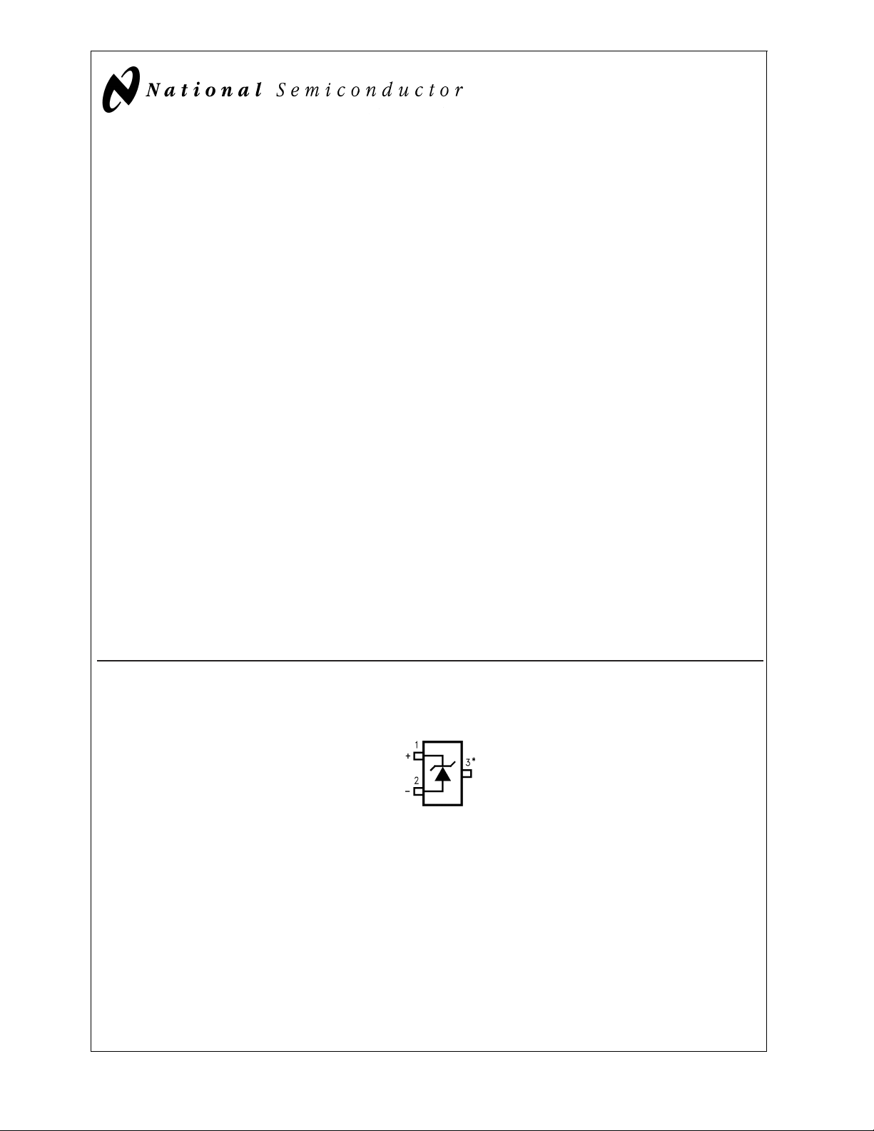
Connection Diagrams
SSOT-23
DS101045-1
*This pin must be left floating or connected to pin 2.
Top View
See NS Package Number MF03A
May 2000
LM4050 Precision Micropower Shunt Voltage Reference
© 2000 National Semiconductor Corporation DS101045 www.national.com
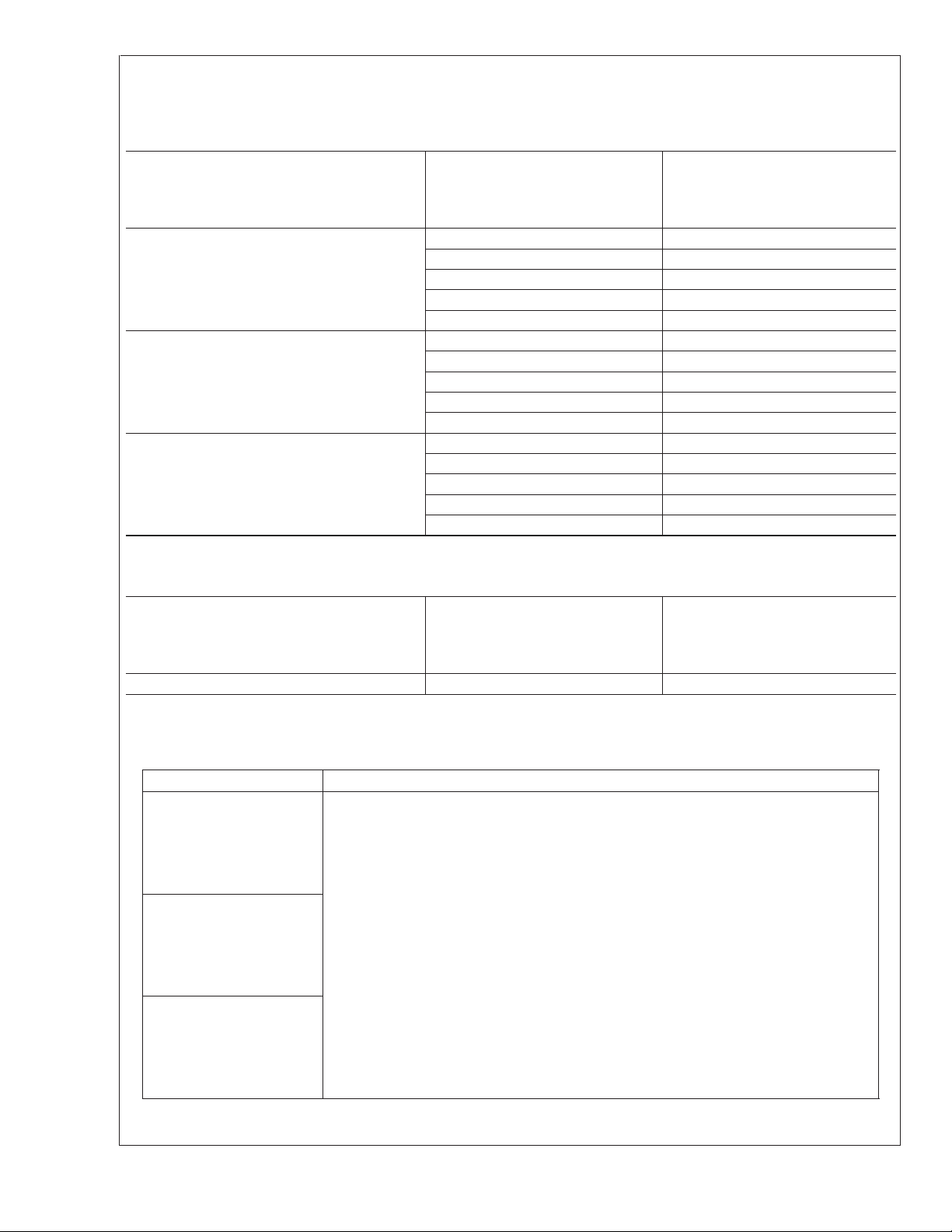
Ordering Information
Industrial Temperature Range (−40 ˚C to +85 ˚C)
Reverse Breakdown
Voltage Tolerance at 25˚C and Average
Reverse Breakdown
Voltage Temperature Coefficient
LM4050 Supplied as 1000 Units,
Tape and Reel
LM4050 Supplied as 3000 Units,
Tape and Reel
±
0.1%, 50 ppm/˚C max (A grade)
LM4050AIM3-2.5 LM4050AIM3X-2.5
LM4050AIM3-4.1 LM4050AIM3X-4.1
LM4050AIM3-5.0 LM4050AIM3X-5.0
LM4050AIM3-8.2 LM4050AIM3X-8.2
LM4050AIM3-10 LM4050AIM3X-10
±
0.2%, 50 ppm/˚C max (B grade)
LM4050BIM3-2.5 LM4050BIM3X-2.5
LM4050BIM3-4.1 LM4050BIM3X-4.1
LM4050BIM3-5.0 LM4050BIM3X-5.0
LM4050BIM3-8.2 LM4050BIM3X-8.2
LM4050BIM3-10 LM4050BIM3X-10
±
0.5%, 50 ppm/˚C max (C grade)
LM4050CIM3-2.5 LM4050CIM3X-2.5
LM4050CIM3-4.1 LM4050CIM3X-4.1
LM4050CIM3-5.0 LM4050CIM3X-5.0
LM4050CIM3-8.2 LM4050CIM3X-8.2
LM4050CIM3-10 LM4050CIM3X-10
Extended Temperature Range (−40 ˚C to +125 ˚C)
Reverse Breakdown
Voltage Tolerance at 25˚C and Average
Reverse Breakdown
Voltage Temperature Coefficient
LM4050 Supplied as 1000 Units,
Tape and Reel
LM4050 Supplied as 3000 Units,
Tape and Reel
±
0.5%, 50 ppm/˚C max (C grade) LM4050CEM3-2.5 LM4050CEM3X-2.5
SSOT-23 Package Marking Information
Only three fields of marking are possible on the SSOT-23’s small surface. This table gives the meaning of the three fields.
Part Marking Field Definition
RCA First Field:
RDA R = Reference
REA Second Field:
RFA C = 2.500V Voltage Option
RGA D = 4.096V Voltage Option
RCB E = 5.000V Voltage Option
RDB F = 8.192V Voltage Option
REB G = 10.000V Voltage Option
RFB
RGB Third Field:
RCC A–C = Initial Reverse Breakdown Voltage or Reference Voltage Tolerance
RDC A =
±
0.1%, B =
±
0.2%, C = +0.5%,
REC
RFC
RGC
LM4050
www.national.com 2

Absolute Maximum Ratings (Note 1)
If Military/Aerospace specified devices are required,
please contact the National Semiconductor Sales Office/
Distributors for availability and specifications.
Reverse Current 20 mA
Forward Current 10 mA
Power Dissipation (T
A
= 25˚C) (Note 3)
M3 Package 280 mW
Storage Temperature (Note 2) −65˚C to +150˚C
Lead Temperature
M3 Package
Vapor phase (60 seconds) +215˚C
Infrared (15 seconds) +220˚C
ESD Susceptibility
Human Body Model (Note 4) 2 kV
Machine Model (Note 4) 200V
See AN-450 “Surface Mounting Methods and Their Effect
on Product Reliability” for other methods of soldering
surface mount devices.
Operating Ratings(Notes 1, 3)
Temperature Range (T
min
≤ T
A
≤ T
max
)
Industrial Temperature Range −40˚C ≤ T
A
≤ +85˚C
Extended temperature Range −40˚C ≤ T
A
≤ +125˚C
Reverse Current
LM4050-2.5 60 µA to 15 mA
LM4050-4.1 68 µA to 15 mA
LM4050-5.0 74 µA to 15 mA
LM4050-8.2 91 µA to 15 mA
LM4050-10.0 100 µA to 15 mA
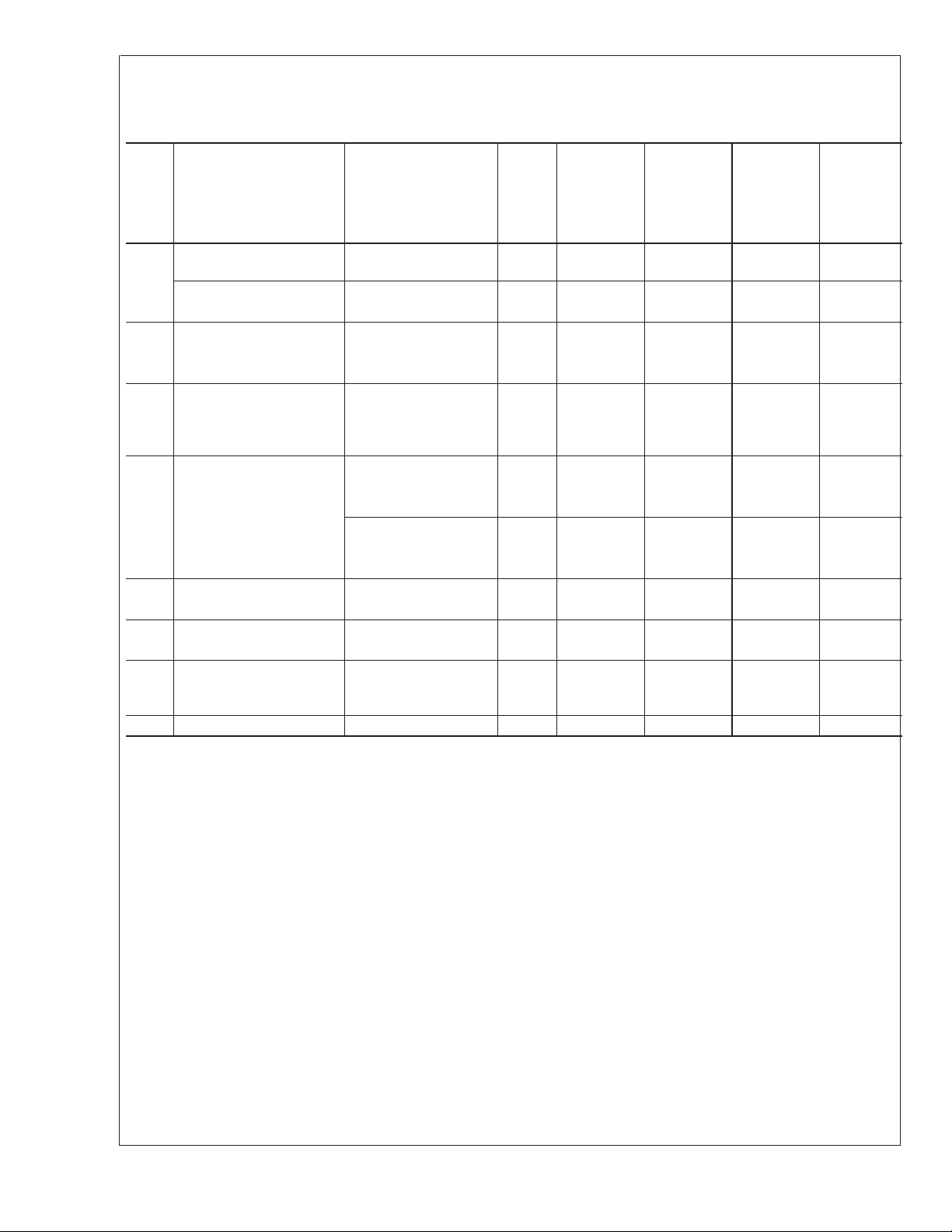
LM4050-2.5
Electrical Characteristics
Boldface limits apply for T
A
=T
J
=T
MIN
to T
MAX
; all other limits T
A
=T
J
= 25˚C. The grades A, B and C designate initial Re-
verse Breakdown Voltage tolerances of
±
0.1%,
±
0.2%, and 0.5% respectively.
Symbol Parameter Conditions Typical
(Note 5)
LM4050AIM3
Limits
(Note 6)
LM4050BIM3
Limits
(Note 6)
LM4050CIM3
LM4050CEM3
Limits
(Note 6)
Units
(Limit)
V
R
Reverse Breakdown
Voltage
I
R
= 100 µA 2.500 V
Reverse Breakdown
Voltage Tolerance (Note 7)
I
R
= 100 µA
±
2.5
±
5.0
±
13 mV (max)
Industrial Temp. Range
Devices
±
11
±
14
±
21 mV (max)
Extended Temp. Range
Devices
±
25 mV (max)
I
RMIN
Minimum Operating Current 41 µA
60 60 60 µA (max)
65 65 65 µA (max)
∆V
R
/∆T Average Reverse
Breakdown Voltage
Temperature Coefficient
(Note 7)
I
R
=10mA
±
20 ppm/˚C
I
R
=1mA
±
15 ppm/˚C
I
R
= 100 µA
±
15
±
50
±
50
±
50 ppm/˚C (max)
∆V
R
/∆I
R
Reverse Breakdown
Voltage Change with
Operating Current Change
(Note 8)
I
RMIN
≤ I
R
≤ 1 mA 0.3 mV
0.8 0.8 0.8 mV (max)
1.2 1.2 1.2 mV (max)
1mA≤I
R
≤15 mA 2.3 mV
6.0 6.0 6.0 mV (max)
8.0 8.0 8.0 mV (max)
Z
R
Reverse Dynamic
Impedance
I
R
= 1 mA, f = 120 Hz,
I
AC
= 0.1 I
R
0.3 Ω
e
N
Wideband Noise I
R
= 100 µA 41 µV
rms
10 Hz ≤ f ≤ 10 kHz
∆V
R
Reverse Breakdown
Voltage Long Term Stability
t = 1000 hrs
T = 25˚C
±
0.1˚C
I
R
= 100 µA
120 ppm
V
HYST
Output Hysteresis ∆T = −40˚C to 125˚C 0.7 mV
LM4050
www.national.com3
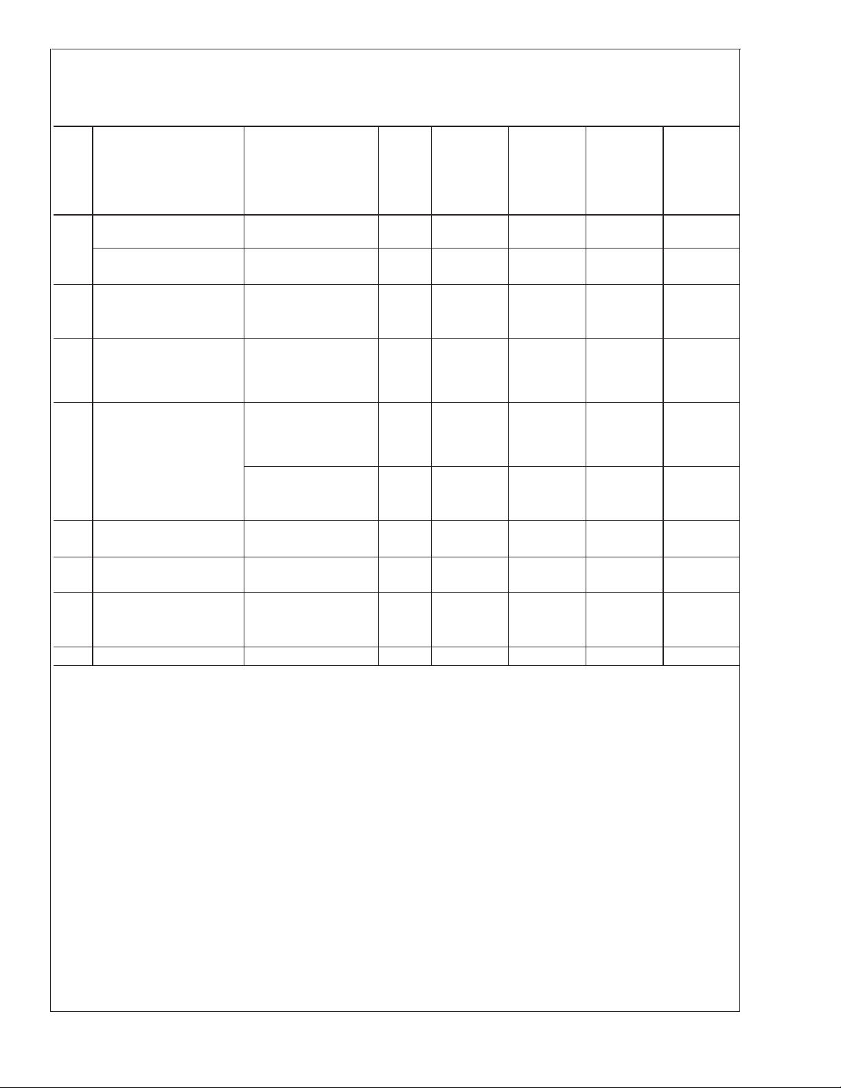
LM4050-4.1
Electrical Characteristics (Industrial Temperature Range)
Boldface limits apply for T
A
=T
J
=T
MIN
to T
MAX
; all other limits T
A
=T
J
= 25˚C. The grades A, B and C designate initial Re-
verse Breakdown Voltage tolerances of
±
0.1%,
±
0.2%, and 0.5% respectively.
Symbol Parameter Conditions
Typical
(Note 5)
Units
(Limit)
LM4050AIM3 LM4050BIM3 LM4050CIM3
Limits Limits Limits
(Note 6) (Note 6) (Note 6)
V
R
Reverse Breakdown
Voltage
I
R
= 100 µA 4.096 V
Reverse Breakdown
Voltage Tolerance (Note 7)
I
R
= 100 µA
±
4.1
±
8.2
±
21 mV (max)
±
18
±
22
±
34 mV (max)
I
RMIN
Minimum Operating Current 52 µA
68 68 68 µA (max)
73 73 73 µA (max)
∆V
R
/∆T Average Reverse
Breakdown Voltage
Temperature
Coefficient(Note 7)
I
R
=10mA
±
30 ppm/˚C
I
R
=1mA
±
20 ppm/˚C
I
R
= 100 µA
±
20
±
50
±
50
±
50 ppm/˚C (max)
∆V
R
/∆I
R
Reverse Breakdown
Voltage Change with
Operating Current Change
(Note 8)
I
RMIN
≤ I
R
≤ 1 mA 0.2 mV
0.9 0.9 0.9 mV (max)
1.2 1.2 1.2 mV (max)
1mA≤I
R
≤15 mA 2.0 mV
7.0 7.0 7.0 mV (max)
10.0 10.0 10.0 mV (max)
Z
R
Reverse Dynamic
Impedance
I
R
= 1 mA, f = 120 Hz, 0.5 Ω
I
AC
= 0.1 I
R
e
N
Wideband Noise I
R
= 100 µA 93 µV
rms
10 Hz ≤ f ≤ 10 kHz
∆V
R
Reverse Breakdown
Voltage Long Term Stability
t = 1000 hrs
T = 25˚C
±
0.1˚C
I
R
= 100 µA
120 ppm
V
HYST
Output Hysteresis ∆T = −40˚C to 125˚C 1.148 mV
LM4050
www.national.com 4
LM4050-5.0
Electrical Characteristics (Industrial Temperature Range)
Boldface limits apply for T
A
=T
J
=T
MIN
to T
MAX
; all other limits T
A
=T
J
= 25˚C. The grades A, B and C designate initial Re-
verse Breakdown Voltage tolerances of
±
0.1%,
±
0.2% and 0.5% respectively.
Symbol Parameter Conditions
Typical
(Note 5)
Units
(Limit)
LM4050AIM3 LM4050BIM3 LM4050CIM3
Limits
Limits Limits
(Note 6) (Note 6) (Note 6)
V
R
Reverse Breakdown
Voltage
I
R
= 100 µA 5.000 V
Reverse Breakdown
Voltage Tolerance (Note 7)
I
R
= 100 µA
±
5.0
±
10
±
25 mV (max)
±
22
±
27
±
42 mV (max)
I
RMIN
Minimum Operating Current 56 µA
74 74 74 µA (max)
80 80 80 µA (max)
∆V
R
/∆T Average Reverse
Breakdown Voltage
Temperature Coefficient
(Note 7)
I
R
=10mA
±
30 ppm/˚C
I
R
=1mA
±
20 ppm/˚C
I
R
= 100 µA
±
20
±
50
±
50
±
50 ppm/˚C (max)
∆V
R
/∆I
R
Reverse Breakdown
Voltage Change with
Operating Current Change
(Note 8)
I
RMIN
≤ I
R
≤ 1 mA 0.2 mV
1.0 1.0 1.0 mV (max)
1.4 1.4 1.4 mV (max)
1mA≤I
R
≤15 mA 2.0 mV
8.0 8.0 8.0 mV (max)
12.0 12.0 12.0 mV (max)
Z
R
Reverse Dynamic
Impedance
I
R
= 1 mA, f = 120 Hz, 0.5 Ω
I
AC
= 0.1 I
R
Ω (max)
e
N
Wideband Noise I
R
= 100 µA 93 µV
rms
10 Hz ≤ f ≤ 10 kHz
∆V
R
Reverse Breakdown
Voltage Long Term Stability
t = 1000 hrs
T = 25˚C
±
0.1˚C 120 ppm
I
R
= 100 µA
V
HYST
Output Hysteresis ∆T = −40˚C to 125˚C 1.4 mV
LM4050
www.national.com5
 Loading...