


LM4120AIM5-4.1
NSC LM4120AIM5-4.1, LM4120AIM5-3.0, LM4120AIM5-2.5, LM4120AIM5-2.0, LM4120AIM5-1.8 Datasheet
...
February 2000
LM4120
Precision Micropower Low Dropout Voltage Reference
LM4120 Precision Micropower Low Dropout Voltage Reference
General Description
The LM4120 is a precision low power low dropout bandgap
voltage reference with up to 5 mA output current source and
sink capability.
This series reference operates with input voltages as low as
2V and up to 12V consuming 160 µA(Typ.) supply current. In
power down mode, device current drops to less than 2 µA.
The LM4120 comes in two grades (A and Standard) and
seven voltage options for greater flexibility. The best grade
devices (A) have an initial accuracy of 0.2%, while the standard have an initial accuracy of 0.5%, both with a tempco of
50ppm/˚C guaranteed from −40˚C to +125˚C.
The very low dropout voltage, low supply current and
power-down capability of the LM4120 makes this product an
ideal choice for battery powered and portable applications.
The device performance is guaranteed over the industrial
temperature range (−40˚C to +85˚C), while certain specs are
guaranteed over the extended temperature range (−40˚C to
+125˚C). Please contact National for full specifications over
the extended temperature range. The LM4120 is available in
a standard 5-pin SOT-23 package.
Features
n Small SOT23-5 package
n Low dropout voltage: 120 mV Typ
n High output voltage accuracy: 0.2
n Source and Sink current output:
n Supply current: 160 µA Typ.
n Low Temperature Coefficient: 50 ppm/˚C
n Enable pin
n Fixed output voltages: 1.8, 2.048, 2.5, 3.0, 3.3, 4.096
and 5.0V
n Industrial temperature Range: −40˚C to +85˚C
n (For extended temperature range, −40˚C to 125˚C,
contact National Semiconductor)
@
±
1mA
5mA
Applications
n Portable, battery powered equipment
n Instrumentation and process control
n Automotive & Industrial
n Test equipment
n Data acquisition systems
n Precision regulators
n Battery chargers
n Base stations
n Communications
n Medical equipment
%
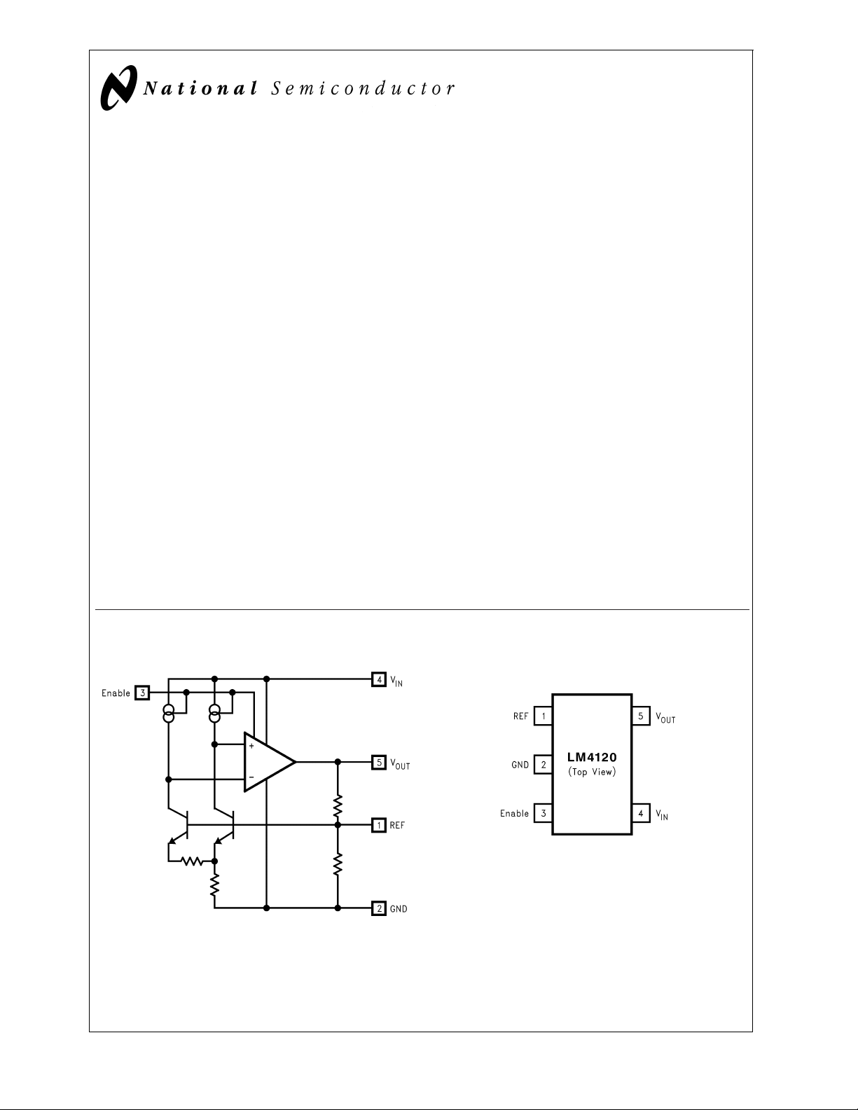
Functional Block Diagram
DS101047-1
Connection Diagram
DS101047-2
Refer to the Ordering Information Table in this Data Sheet for Specific
Part Number
SOT23-5 Surface Mount Package
© 2000 National Semiconductor Corporation DS101047 www.national.com
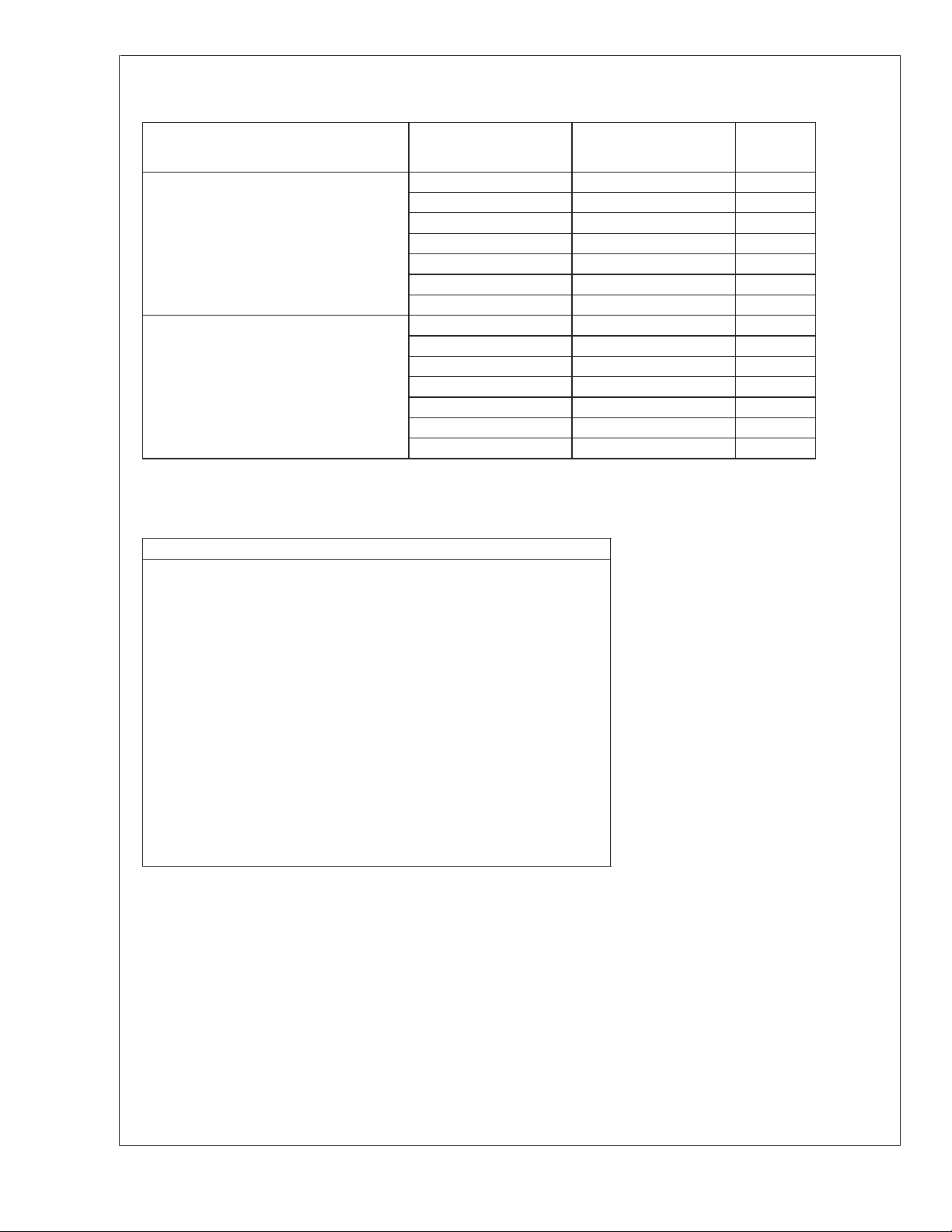
Ordering Information
LM4120
Industrial Temperature Range (−40˚C to + 85˚C)
Initial Output Voltage Accuracy at 25˚C
And Temperature Coefficient
0.2%, 50 ppm/˚C max (A grade)
0.5%, 50 ppm/˚C max
LM4120 Supplied as
1000 Units, Tape and
Reel
LM4120AIM5-1.8 LM4120AIM5X-1.8 R21A
LM4120AIM5-2.0 LM4120AIM5X-2.0 R14A
LM4120AIM5-2.5 LM4120AIM5X-2.5 R08A
LM4120AIM5-3.0 LM4120AIM5X-3.0 R15A
LM4120AIM5-3.3 LM4120AIM5X-3.3 R16A
LM4120AIM5-4.1 LM4120AIM5X-4.1 R17A
LM4120AIM5-5.0 LM4120AIM5X-5.0 R18A
LM4120IM5-1.8 LM4120IM5X-1.8 R21B
LM4120IM5-2.0 LM4120IM5X-2.0 R14B
LM4120IM5-2.5 LM4120IM5X-2.5 R08B
LM4120IM5-3.0 LM4120IM5X-3.0 R15B
LM4120IM5-3.3 LM4120IM5X-3.3 R16B
LM4120IM5-4.1 LM4120IM5X-4.1 R17B
LM4120IM5-5.0 LM4120IM5X-5.0 R18B
SOT-23 Package Marking Information
Only four fields of marking are possible on the SOT-23’s small surface. This
table gives the meaning of the four fields.
Field Information
First Field:
R=Reference
Second and third Field:
21=1.800V Voltage Option
14=2.048V Voltage Option
08=2.500V Voltage Option
15=3.000V Voltage Option
16=3.300V Voltage Option
17=4.096V Voltage Option
18=5.000V Voltage Option
Fourth Field:
A-B=Initial Reference Voltage Tolerance
=
±
A
B
%
0.2
=
±
%
0.5
LM4120 Supplied as
3000 Units, Tape and
Reel
Top
Marking
www.national.com 2
LM4120
Absolute Maximum Ratings (Note 1)
If Military/Aerospace specified devices are required,
please contact the National Semiconductor Sales Office/
Distributors for availability and specifications.
Lead Temperature:
Soldering, (10 sec.) +260˚C
Vapor Phase (60 sec.) +215˚C
Infrared (15 sec.) +220˚C
Maximum Voltage on input or
enable pins −0.3V to 14V
Output Short-Circuit Duration Indefinite
Power Dissipation (T
MA05B package − θ
= 25˚C) (Note 2):
A
JA
280˚C/W
Operating Range (Note 1)
Storage Temperature Range −65˚C to +150˚C
Ambient Temperature Range −40˚C to +85˚C
Junction Temperature Range −40˚C to +125˚C
Power Dissipation 350 mW
ESD Susceptibility (Note 3)
Human Body Model
Machine Model
2kV
200V
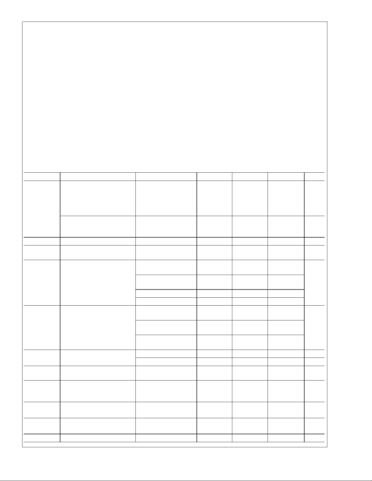
Electrical Characteristics
LM4120-1.8V, 2.048V and 2.5V
=
25˚C. Limits with standard typeface are for T
j
Unless otherwise specified V
=
25˚C, and limits in boldface type apply over the −40˚C ≤ T
=
3.3V, I
IN
perature range.
Symbol Parameter Conditions Min (Note 5) Typ (Note 4) Max (Note 5) Units
Output Voltage Initial
Accuracy
LM4120A-1.800
V
OUT
LM4120A-2.048
LM4120A-2.500
LM4120-1.800
LM4120-2.048
LM4120-2.500
TCV
∆V
∆V
V
V
/˚C Temperature Coefficient −40˚C ≤ TA≤ +125˚C 14 50 ppm/˚c
OUT
/∆V
OUT
/∆I
OUT
IN−VOUT
N
Line Regulation 3.3V ≤ VIN≤ 12V 0.0007 0.008
IN
≤ 1 mA 0.03 0.08
LOAD
≤ 5 mA 0.01 0.04
LOAD
≤ 0 mA 0.04 0.12
LOAD
≤ −1 mA 0.01
LOAD
Load Regulation
LOAD
Dropout Voltage (Note 6)
0mA≤I
1mA≤I
−1 mA ≤ I
−5 mA ≤ I
=0mA 45 65
I
LOAD
= +1 mA 120 150
I
LOAD
I
= +5 mA 180 210
LOAD
Output Noise Voltage (Note 8) 0.1 Hz to 10 Hz 20 µV
10 Hz to 10 kHz 36 µV
I
S
I
SS
Supply Current 160 250
Power-down Supply Current Enable=0.4V
−40˚C ≤ T
≤ +85˚C
J
Enable=0.2V
V
H
Logic High Input Voltage 2.4 V
2.4
V
L
I
H
Logic Low Input Voltage 0.4 V
Logic High Input Current 7 15 µA
LOAD
=
0, C
OUT
=
0.01µF, T
≤ +85˚C tem-
A
±
0.2
±
0.5
0.01
0.17
0.1
80
180
250
275
1
2 µA
0.2
=
T
A
j
%
%
%
/V
%
/mA
mV
PP
PP
µA
www.national.com3
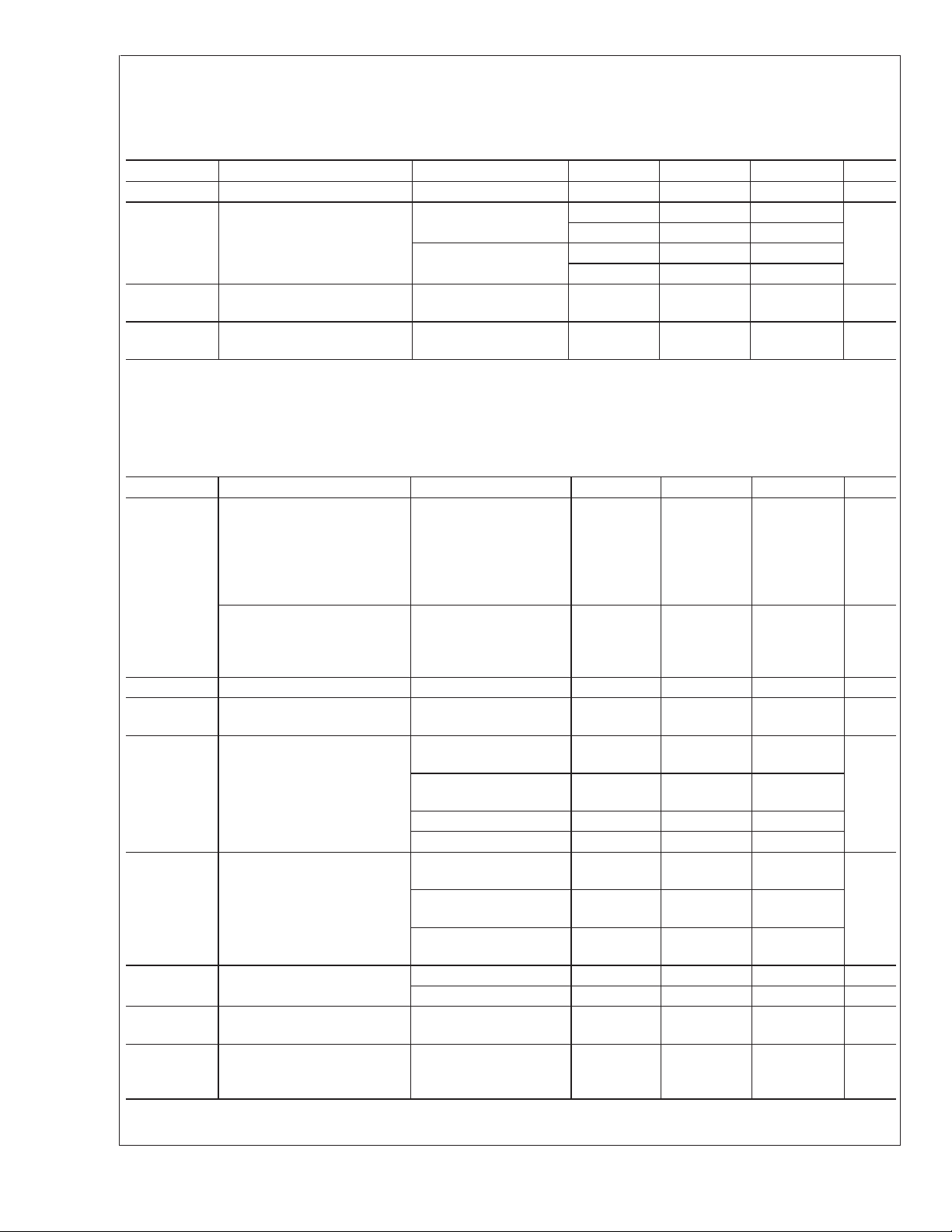
Electrical Characteristics
LM4120-1.8V, 2.048V and 2.5V
LM4120
=
25˚C. Limits with standard typeface are for T
Unless otherwise specified V
=
25˚C, and limits in boldface type apply over the −40˚C ≤ T
j
=
3.3V, I
IN
temperature range. (Continued)
Symbol Parameter Conditions Min (Note 5) Typ (Note 4) Max (Note 5) Units
I
L
I
SC
Logic Low Input Current 0.1 µA
Short Circuit Current
=
3.3V, V
V
IN
=
V
12V, V
IN
=
015
OUT
630
=
017
OUT
630
Hyst Thermal Hysteresis
−40˚C ≤ T
≤ 125˚C 0.5 mV/V
A
(Note 7)
∆V
OUT
Long Term Stability
1000 hrs.@25˚C 100 ppm
(Note 9)
LOAD
=
0, C
OUT
=
0.01µF, T
≤ +85˚C
A
Electrical Characteristics
LM4120-3.0V, 3.3V, 4.096V and 5.0V
=
0.01µF, T
T
≤ +85˚C temperature range.
A
=
T
A
25˚C. Limits with standard typeface are for T
j
Unless otherwise specified V
=
25˚C, and limits in boldface type apply over the −40˚C ≤
j
Symbol Parameter Conditions Min (Note 5) Typ (Note 4) Max (Note 5) Units
Output Voltage Initial
Accuracy
LM4120A-3.000
LM4120A-3.300
V
OUT
LM4120A-4.096
LM4120A-5.000
LM4120-3.000
LM4120-3.300
LM4120-4.096
LM4120-5.000
TCV
∆V
∆V
V
V
/˚C Temperature Coefficient −40˚C ≤ TA≤ +125˚C 14 50 ppm/˚c
OUT
/∆V
OUT
/∆I
OUT
IN−VOUT
N
Line Regulation (V
IN
Load Regulation
LOAD
Dropout Voltage (Note 6)
+ 1V) ≤ VIN≤ 12V 0.0007 0.008
OUT
0mA≤I
1mA≤I
−1 mA ≤ I
−5 mA ≤ I
=0mA 45 65
I
LOAD
= +1 mA 120 150
I
LOAD
I
= +5 mA 180 210
LOAD
≤ 1 mA 0.03 0.08
LOAD
≤ 5 mA 0.01 0.04
LOAD
≤ 0 mA 0.04 0.12
LOAD
≤ −1 mA 0.01
LOAD
Output Noise Voltage (Note 8) 0.1 Hz to 10 Hz 20 µV
10 Hz to 10 kHz 36 µV
I
S
I
SS
Supply Current 160 250
Power-down Supply Current Enable=0.4V
−40˚C ≤ T
≤ +85˚C
J
Enable=0.2V
=
IN
+ 1V, I
V
OUT
LOAD
±
0.2
±
0.5
0.01
0.17
0.1
80
180
250
275
1
2 µA
=
T
A
j
mA
=
0, C
OUT
=
%
%
%
/V
%
/mA
mV
PP
PP
µA
www.national.com 4
 Loading...