


 Loading...
User Manual
8-Port Gigabit Ethernet
Smart Managed Plus Switch with Integrated Cable Management
Model GS908E
|
NETGEAR, Inc. |
August 2018 |
350 E. Plumeria Drive |
202-11807-04 |
San Jose, CA 95134, USA |
8-Port Gigabit Ethernet
Support
Thank you for purchasing this NETGEAR product. You can visit https://www.netgear.com/support/toregisteryourproduct,gethelp,accessthelatest downloads and user manuals, and join our community. We recommend that you use only official NETGEAR support resources.
Compliance and Conformity
ForregulatorycomplianceinformationincludingtheEUDeclarationofConformity,visit https://www.netgear.com/about/regulatory/.
See the regulatory compliance document before connecting the power supply.
Do not use this device outdoors. If you connect cables or devices that are outdoors to thisdevice,see http://kb.netgear.com/000057103 forsafetyandwarrantyinformation.
Trademarks
©NETGEAR,Inc.,NETGEAR,andtheNETGEARLogoaretrademarksofNETGEAR,Inc. Any non-NETGEAR trademarks are used for reference purposes only.
Revision History
PublicationPart |
Publish Date |
Comments |
Number |
|
|
202-11807-04 |
August 2018 |
Added Safety Instructions and Warnings on page 10. |
|
|
Added Change the Language of the Local Browser Interface on page 24. |
|
|
Changed VLAN Overview on page 44. |
|
|
Added Control Management Access to the Switch on page 75. |
|
|
Added Change or Lift Access Restrictions to the Switch on page 76. |
|
|
Changed Quiet mode to Stealth Mode throughout the manual. |
|
|
Made minor changes to other sections. |
202-11807-03 |
December 2017 |
Added AccesstheSwitchFromaMacorWindows-BasedComputerUsing |
|
|
the NETGEAR Switch Discovery Tool on page 17. |
|
|
Removed information about accessing a switch from a Mac using a Firefox |
|
|
plug-in. |
202-11807-02 |
November 2017 |
Added information about accessing a switch from a Mac using a Firefox |
|
|
plug-in. |
202-11807-01 |
October 2017 |
First publication. |
2

Contents
Chapter 1 Hardware Overview of the Switch |
|
Related Documentation....................................................................... |
7 |
Switch Package Contents..................................................................... |
7 |
Status LEDs............................................................................................ |
8 |
Back Panel.............................................................................................. |
9 |
Switch Label........................................................................................ |
10 |
Safety Instructions and Warnings..................................................... |
10 |
Chapter 2 Install and Access the Switch in Your Network |
|
Set Up the Switch in Your Network and Power On the Switch..... |
14 |
Methods to Discover and Access the Switch.................................. |
14 |
Access the Switch and Discover the IP Address of the Switch...... |
15 |
Access the Switch From a Windows-Based Computer............. |
15 |
Access the Switch From a Mac Using Bonjour........................... |
16 |
Access the Switch From a Mac or Windows-Based Computer |
|
Using the NETGEAR Switch Discovery Tool............................... |
17 |
Set Up a Fixed IP Address for the Switch.................................... |
18 |
Set Up a Fixed IP Address for the Switch Through a Network |
|
Connection................................................................................. |
19 |
SetUpaFixedIPAddressfortheSwitchbyConnectingDirectly |
|
to the Switch Off-Network........................................................ |
20 |
Use the NETGEAR Insight App to Access the Switch..................... |
22 |
Use the NETGEAR ProSAFE Plus Utility to Discover the Switch.... |
23 |
Change the Language of the Local Browser Interface.................. |
24 |
Change the Switch Password............................................................ |
25 |
Register the Switch............................................................................. |
26 |
Chapter 3 Optimize the Switch Performance |
|
Manually Set the Quality of Service Mode and Port Rate Limits.... |
28 |
Use Port-Based Quality of Service and Set Port Priorities......... |
28 |
Use 802.1P/DSCP Quality of Service........................................... |
30 |
Manage Broadcast Filtering and Set Port Storm Control Rate |
|
Limits.................................................................................................... |
31 |
Manage Custom Performance Preset Modes................................. |
33 |
Save Your Quality of Service Settings as a Custom Preset |
|
Mode............................................................................................... |
33 |
3

8-Port Gigabit Ethernet Smart Managed Plus Switch Model GS908E
Apply a Custom Preset Mode...................................................... |
34 |
Apply the Standard Preset Mode................................................. |
34 |
Rename a Custom Preset Mode.................................................. |
35 |
Delete a Custom Preset Mode..................................................... |
36 |
Manage Individual Port Settings....................................................... |
37 |
Set Rate Limits for a Port............................................................... |
37 |
Set the Priority for a Port............................................................... |
38 |
Manage Flow Control for a Port................................................... |
39 |
Change the Speed for a Port or Disable a Port.......................... |
40 |
Add or Change the Name Label for a Port................................. |
41 |
Chapter 4 Use VLANS for Traffic Segmentation |
|
VLAN Overview................................................................................... |
44 |
Manage Port-Based VLANs............................................................... |
45 |
Activate the Port-Based VLAN Mode.......................................... |
45 |
Create a Port-Based VLAN............................................................ |
45 |
Change a Port-Based VLAN.......................................................... |
47 |
Delete a Port-Based VLAN............................................................ |
48 |
Manage 802.1Q-Based VLANs......................................................... |
48 |
Activate the 802.1Q-Based VLAN Mode..................................... |
49 |
Create an 802.1Q-Based VLAN.................................................... |
49 |
Change an 802.1Q-Based VLAN................................................. |
51 |
Delete an 802.1Q-Based VLAN.................................................... |
52 |
Specify a Port PVID for an 802.1Q-Based VLAN........................ |
53 |
SetanExisting802.1Q-BasedVLANastheVoiceVLANandAdjust |
|
the CoS Value................................................................................. |
54 |
Change the OUI Table for the Voice VLAN................................ |
55 |
DeactivatethePort-Basedor802.1Q-BasedVLANModeandDelete |
|
All VLANs............................................................................................. |
57 |
Chapter 5 Manage the Switch in Your Network |
|
Manage Switch Discovery Protocols................................................ |
59 |
Manage Universal Plug and Play.................................................. |
59 |
Manage Bonjour............................................................................. |
60 |
Manage NETGEAR Switch Discovery Protocol........................... |
60 |
Manage Multicast............................................................................... |
61 |
Manage IGMP Snooping............................................................... |
61 |
Enable a VLAN for IGMP Snooping............................................. |
62 |
Manage Blocking of Unknown Multicast Addresses................. |
63 |
Manage IGMPv3 IP Header Validation........................................ |
63 |
Set Up a Static Router Port for IGMP Snooping......................... |
64 |
Set Up Static Link Aggregation......................................................... |
65 |
Set Up a Link Aggregation Group............................................... |
66 |
Make a Link Aggregation Connection........................................ |
67 |
4

8-Port Gigabit Ethernet Smart Managed Plus Switch Model GS908E
Enable a Link Aggregation Group............................................... |
67 |
Change the IP Address of the Switch............................................... |
68 |
Reenable the DHCP Client of the Switch......................................... |
69 |
Chapter 6 Maintain and Monitor the Switch |
|
Manually Check for New Switch Firmware and Update the |
|
Switch................................................................................................... |
71 |
Manage the Configuration File......................................................... |
72 |
Back Up the Switch Configuration............................................... |
72 |
Restore the Switch Configuration................................................ |
73 |
Return the Switch to Its Factory Default Settings............................ |
74 |
Use the Reset Button to Reset the Switch................................... |
74 |
Use the Local Browser Interface to Reset the Switch................. |
75 |
Control Management Access to the Switch.................................... |
75 |
Change or Lift Access Restrictions to the Switch............................ |
76 |
Manage the Power Saving Mode..................................................... |
77 |
Control the LEDs................................................................................. |
78 |
Change the Switch Device Name..................................................... |
79 |
View System Information................................................................... |
79 |
View Switch Connections................................................................... |
80 |
View the Status of a Port.................................................................... |
80 |
View the Port Statistics....................................................................... |
81 |
Chapter 7 Diagnostics and Troubleshooting |
|
Manage Auto-Diagnostics and Clear Events or Problems............ |
83 |
Manage Loop Prevention.................................................................. |
84 |
Enable Port Mirroring......................................................................... |
85 |
Test a Cable Connection................................................................... |
86 |
Reboot the Switch From the Local Browser Interface.................... |
87 |
Resolve a Subnet Conflict to Access the Switch............................. |
88 |
Appendix A Factory Default Settings and Technical Specifications |
|
Factory Default Settings..................................................................... |
90 |
Basic Technical Specifications.......................................................... |
91 |
Appendix B Wall-Mount the Switch |
|
5

1
Hardware Overview of the Switch
The NETGEAR 8-Port Gigabit Ethernet Smart Managed Plus Switch with Integrated CableManagementModelGS908E,inthismanualreferredtoastheswitch,isintended for the home or small office. In addition to integrated cable management, the switch features two USB charging ports.
You can manage the switch over the local browser–based management interface that you can access from a computer or from a smartphone on which the NETGEAR Insight app is installed.
You can optimize Quality of Service (QoS) and set up prioritization and rate limiting for individualports.Theswitchsupportsport-basedor802.1Q-basedVLANs,IGMPsnooping for multicast operation, and link aggregation for a connection of up to 4 Gbps to link aggregation–enabled devices such as ReadyNAS.
The chapter contains the following sections:
•Related Documentation
•Switch Package Contents
•Status LEDs
•Back Panel
•Switch Label
•Safety Instructions and Warnings
Note: For more information about the topics that are covered in this manual, visit the support website at netgear.com/support.
Note: Firmwareupdateswithnewfeaturesandbugfixesaremadeavailablefromtime to time at netgear.com/support/download/. You can check for and download new firmware manually. If the features or behavior of your product does not match what is described in this guide, you might need to update your firmware.
6
8-Port Gigabit Ethernet Smart Managed Plus Switch Model GS908E
Related Documentation
The following related documentation is available at netgear.com/support/download/:
•Installation guide
•Data sheet
Switch Package Contents
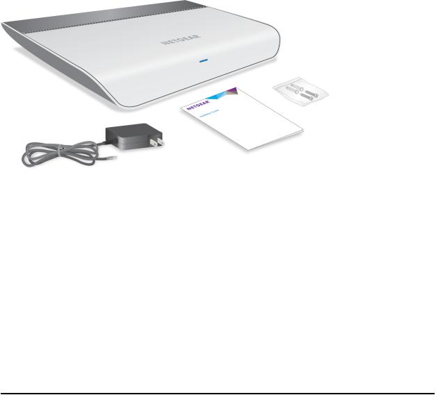
The package contains the switch, AC power adapter (localized to the country of sale), installationguide,wall-mountscrewsandanchors,andcableretentionstrap.(Thestrap is not shown in the following figure).
Figure 1. Switch package contents
Hardware Overview of the |
7 |
User Manual |
Switch |
|
|

8-Port Gigabit Ethernet Smart Managed Plus Switch Model GS908E
Status LEDs
Status LEDs are located on the front panel and back panel of the switch.
Figure 2. Power LED on the front panel
Figure 3. Port LEDs on the back panel
Table 1. LED descriptions
LED
Power LED
Port LEDs (1 through 8)
Description
Off. No power is supplied to the switch or the switch functions in Stealth Mode with its Power LED disabled (see Control the LEDs on page 78).
Solid blue. Power is supplied to the switch and the switch is ready for operation.
Solidamber.Aneventoraproblemoccurred(seeManageAuto-DiagnosticsandClearEvents or Problems on page 83).
Off. No link with a powered-on device is detected or the active ports function in Stealth Mode with their port LEDs disabled (see Control the LEDs on page 78).
Solid green. A 1000M link with a powered-on device is detected. Blinking green. Traffic is detected on the 1000M link.
Solid yellow. A 10M or 100M link with a powered-on device is detected. Blinking yellow. Traffic is detected on the 10M or 100M link.
Hardware Overview of the |
8 |
User Manual |
Switch |
|
|
8-Port Gigabit Ethernet Smart Managed Plus Switch Model GS908E
Back Panel
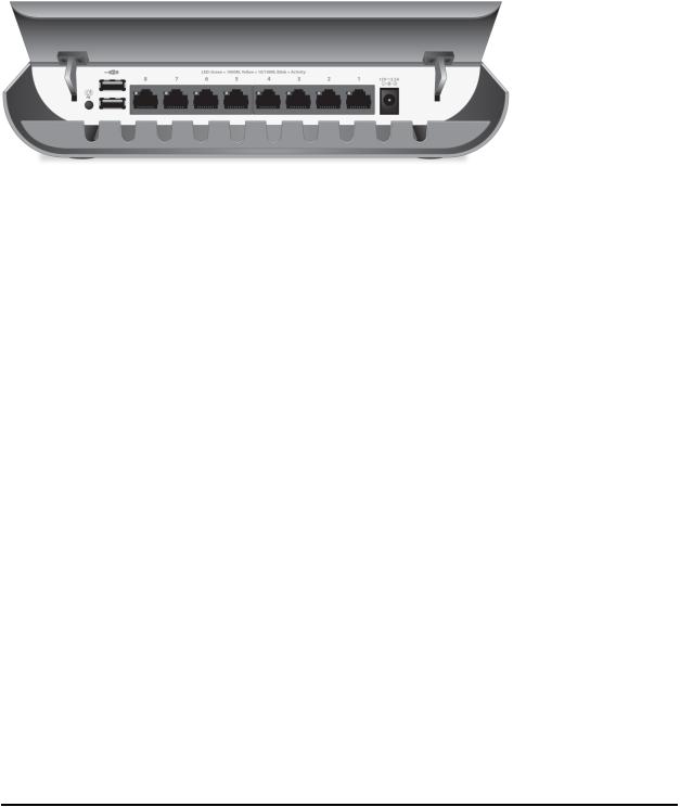
The back panel of the switch provides a LED button, two USB charging ports, eight Ethernet ports, and a DC power connector.
Figure 4. Back panel with cover open
Viewed from left to right, the back panel contains the following components:
•LED button. One button to turn the Power LED and port LEDs on and off.
•USB charging ports. Two USB 2.0 ports for charging USB devices. Each port can provider a maximum of 10W.
Note: Do not use these USB ports to connect storage or network devices. The USB ports are intended for charging only.
•Gigabit Ethernet ports 8 through 1. Eight Gigabit Ethernet RJ-45 LAN ports.
•DC power connector. One 12V, 2.5A DC connector for the power adapter.
Note: The Reset button is located on the bottom panel of the switch. Press the Reset buttonformorethanfivesecondstoresettheswitchtofactorydefaultsettings. For more information, see Return the Switch to Its Factory Default Settings on page 74.
Hardware Overview of the |
9 |
User Manual |
Switch |
|
|
8-Port Gigabit Ethernet Smart Managed Plus Switch Model GS908E
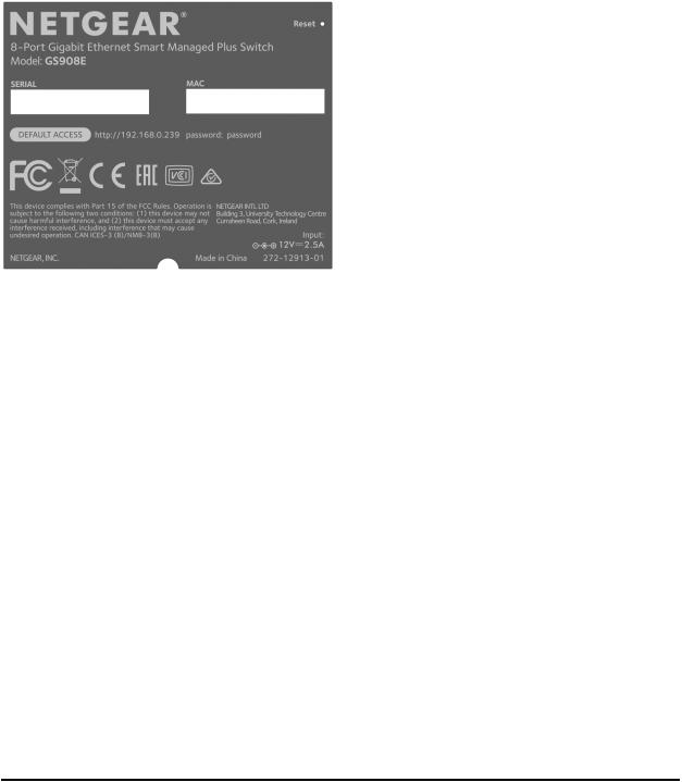
Switch Label
The switch label on the bottom panel of the switch shows the serial number, MAC address, default login information, and other information for the switch. The label also
shows the location of the Reset button.
Figure 5. Switch label
Safety Instructions and Warnings
Use the following safety guidelines to ensure your own personal safety and to help protect your system from potential damage.
Toreducetheriskofbodilyinjury,electricalshock,fire,anddamagetotheequipment, observe the following precautions:
•This product is designed for indoor use only in a temperature-controlled (32–104°F or 0–40°C) and humidity-controlled (90 percent maximum relative humidity, noncondensing) environment. Anydevicethatislocatedoutdoorsandconnectedtothisproductmustbeproperly grounded and surge protected.
To the extent permissible by applicable law, failure to follow these guidelines can result in damage to your NETGEAR product, which might not be covered by NETGEAR’s warranty.
Hardware Overview of the |
10 |
User Manual |
Switch |
|
|
8-Port Gigabit Ethernet Smart Managed Plus Switch Model GS908E
•Observe and follow service markings:
-Do not service any product except as explained in your system documentation.
-Opening or removing covers that are marked with the triangular symbol with a lightning bolt can expose you to electrical shock. We recommend that only a trained technician services components inside these compartments.
•Ifanyofthefollowingconditionsoccur,unplugtheproductfromtheelectricaloutlet and replace the part or contact your trained service provider:
-The power cable, extension cable, or plug is damaged.
-An object fell into the product.
-The product was exposed to water.
-The product was dropped or damaged.
-The product does not operate correctly when you follow the operating instructions.
•Keep your system away from radiators and heat sources.
•Do not spill food or liquids on your system components, and never operate the product in a wet environment. If the system gets wet, see the appropriate section in your troubleshooting guide, or contact your trained service provider.
•Do not push any objects into the openings of your system. Doing so can cause fire or electric shock by shorting out interior components.
•Use the product only with approved equipment.
•Operate the product only from the type of external power source indicated on the electrical ratings label. If you are not sure of the type of power source required, consult your service provider or local power company.
•Toavoiddamagingyoursystem,besurethatthevoltageselectionswitch(ifprovided) on the power supply is set to match the power at your location:
-115V,60HzinmostofNorthandSouthAmericaandsomeFarEasterncountries such as South Korea and Taiwan
-100V, 50 Hz in eastern Japan and 100V, 60 Hz in western Japan
-230V, 50 Hz in most of Europe, the Middle East, and the Far East
•Besurethatattacheddevicesareelectricallyratedtooperatewiththepoweravailable in your location.
•UseonlythesuppliedDCpoweradapter. IfyouwerenotprovidedwithaDCpower adapter, contact your reseller.
Hardware Overview of the |
11 |
User Manual |
Switch |
|
|

8-Port Gigabit Ethernet Smart Managed Plus Switch Model GS908E
•To help prevent electric shock, plug the system and peripheral power cables into properly grounded electrical outlets.
•The peripheral power cables are equipped with three-prong plugs to help ensure proper grounding. Do not use adapter plugs or remove the grounding prong from a cable. If you must use an extension cable, use a three-wire cable with properly grounded plugs.
•Observe extension cable and power strip ratings. Make sure that the total ampere rating of all products plugged into the extension cable or power strip does not exceed80percentoftheampereratingslimitfortheextensioncableorpowerstrip.
•To help protect your system from sudden, transient increases and decreases in electricalpower,useasurgesuppressor,lineconditioner,oruninterruptiblepower supply (UPS).
•Positionsystemcablesandpowercablescarefully. Routecablessothattheycannot be stepped on or tripped over. Be sure that nothing rests on any cables.
•Do not modify power cables or plugs. Consult a licensed electrician or your power company for site modifications.
•Always follow your local and national wiring rules.
Hardware Overview of the |
12 |
User Manual |
Switch |
|
|

2
InstallandAccesstheSwitchinYour
Network
This chapter describes how to install and access the switch in your network.
The chapter contains the following sections:
•Set Up the Switch in Your Network and Power On the Switch
•Methods to Discover and Access the Switch
•Access the Switch and Discover the IP Address of the Switch
•Use the NETGEAR Insight App to Access the Switch
•Use the NETGEAR ProSAFE Plus Utility to Discover the Switch
•Change the Language of the Local Browser Interface
•Change the Switch Password
•Register the Switch
13
8-Port Gigabit Ethernet Smart Managed Plus Switch Model GS908E
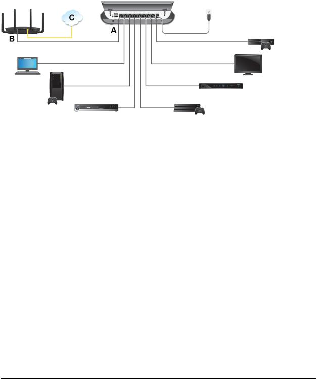
Set Up the Switch in Your Network and Power On the Switch
Figure 6. Sample connections
To set up the switch in your network and power on the switch:
1.Connect one port (A) on the switch to a LAN port (B) on a router that is connected to the Internet (C).
2.Connect your devices to the other LAN ports on the switch.
3.Turnontheswitchbyconnectingthepoweradaptertotheswitchandpluggingthe power adapter into an electrical outlet.
ThebluePowerLEDonthefrontoftheswitchlightsandtheportLEDsforconnected devices light.
Methods to Discover and Access the Switch
You can use any of the following methods to discover the switch in your network and access the switch to configure and manage it:
•Computer and web browser. Use a computer and a web browser to discover the switch in your network and access the local browser interface of the switch (see Access the Switch and Discover the IP Address of the Switch on page 15).
•Insight app. InstalltheNETGEARInsightapponasmartphoneortablettodiscover the switch in your network and access the local browser interface of the switch (see Use the NETGEAR Insight App to Access the Switch on page 22).
Install and Access the Switch in |
14 |
User Manual |
Your Network |
|
|

8-Port Gigabit Ethernet Smart Managed Plus Switch Model GS908E
•ProSAFEPlusUtility.InstalltheNETGEARProSAFE® PlusUtilityonaWindows-based computer and use the utility to discover the switch in your network (see Use the NETGEAR ProSAFE Plus Utility to Discover the Switch on page 23). You cannot perform basic configurations using the ProSAFE Plus Utility. That is, you can only discover the switch in your network. To configure the switch, use the local browser interface of switch.
Access the Switch and Discover the IP Address of the Switch
By default, the switch receives an IP address from a DHCP server (or a router that functions as a DHCP server) in your network.
For information about setting up a fixed (static) IP address on the switch, see Set Up a Fixed IP Address for the Switch on page 18.
Access the Switch From a Windows-Based Computer
To access the switch from a Windows-based computer and discover the switch IP address:
1.Open Windows Explorer or File Explorer.
2.Click the Network link.
3.If prompted, enable the Network Discovery feature.
4.Under Network Infrastructure, locate the GS908E switch.
5.Double-click GS908E (xx:xx:xx:xx:xx:xx), in which xx:xx:xx:xx:xx:xx is the MAC address of the switch.
The login page of the local browser interface opens.
6.Enter the switch password.
The default password is password. The password is case-sensitive. The HOME page displays.
Therightpane(or,dependingonthesizeofyourbrowserwindow,themiddlepane) shows the IP address that is assigned to the switch.
Install and Access the Switch in |
15 |
User Manual |
Your Network |
|
|

8-Port Gigabit Ethernet Smart Managed Plus Switch Model GS908E
Tip: You can copy and paste the IP address into a new shortcut or bookmark it for quickaccessonyourcomputerormobiledevice. However,ifyourestarttheswitch, adynamicIPaddress(assignedbyaDHCPserver)mightchangeandthebookmark might no longer link to the login page for the switch. In that situation, you must repeat this procedure so that you can discover the new IP address of the switch in the network and update your bookmark accordingly. You can also set up a fixed (static) IP address for the switch (see Set Up a Fixed IP Address for the Switch on page 18) to make sure that the new bookmark always links to the login page for the switch, even after you restart the switch.
Access the Switch From a Mac Using Bonjour
If your Mac supports Bonjour, you can use the following procedure. If your Mac does not support Bonjour, see Access the Switch From a Mac or Windows-Based Computer Using the NETGEAR Switch Discovery Tool on page 17.
To access the switch from a Mac using Bonjour and discover the switch IP address:
1.Open the Safari browser.
2.Select Safari > Preferences. The General page displays.
3.Click the Advanced tab. The Advanced page displays.
4.Select the Include Bonjour in the Bookmarks Menu check box.
5.Close the Advanced page.
6.Depending on your Mac OS version, select one of the following, in which xx:xx:xx:xx:xx:xx is the MAC address of the switch:
•Bookmarks > Bonjour > GS908E (xx:xx:xx:xx:xx:xx)
•Bookmarks > Bonjour > Webpages GS908E (xx:xx:xx:xx:xx:xx)
The login page of the local browser interface opens.
7.Enter the switch password.
The default password is password. The password is case-sensitive. The HOME page displays.
Therightpane(or,dependingonthesizeofyourbrowserwindow,themiddlepane) shows the IP address that is assigned to the switch.
Install and Access the Switch in |
16 |
User Manual |
Your Network |
|
|

8-Port Gigabit Ethernet Smart Managed Plus Switch Model GS908E
Tip: You can copy and paste the IP address into a new shortcut or bookmark it for quickaccessonyourcomputerormobiledevice. However,ifyourestarttheswitch, adynamicIPaddress(assignedbyaDHCPserver)mightchangeandthebookmark might no longer link to the login page for the switch. In that situation, you must repeat this procedure so that you can discover the new IP address of the switch in the network and update your bookmark accordingly. You can also set up a fixed (static) IP address for the switch (see Set Up a Fixed IP Address for the Switch on page 18) to make sure that the new bookmark always links to the login page for the switch, even after you restart the switch.
AccesstheSwitchFromaMacorWindows-BasedComputer
Using the NETGEAR Switch Discovery Tool
The NETGEAR Switch Discovery Tool lets you discover the switch in your network and access the local browser interface of the switch from a Mac or a 64-bit Windows-based computer. If your Mac does not support Bonjour, use the following procedure.
To install the NETGEAR Switch Discovery Tool, discover the switch in your network, access the switch, and discover the switch IP address:
1.Download the Switch Discovery Tool by visiting netgear.com/support/product/netgear-switch-discovery-tool.aspx.
Depending on the computer that you are using, download either the Mac version or the version for a 64-bit Windows-based computer.
2.Temporarilydisablethefirewall,Internetsecurity,antivirusprograms,orallofthese on the computer that you use to configure the switch.
3.Unzip the Switch Discovery Tool files, double-click the Setup.exe file (for example,
NetgearSDT-V1.1.115_Win_x64_Setup.exe), and install the program on your computer.
Dependingonyourcomputersetup,theinstallationprocessmightaddtheNETGEAR Switch Discovery Tool icon to the Dock of your Mac or the desktop of your
Windows-based computer.
4.Reenable the security services on your computer.
5.Power on the switch.
The DHCP server assigns the switch an IP address.
6.Connect your computer to the same network as the switch.
You can use a WiFi or wired connection. The computer and the switch must be on the same Layer 2 network.
7.Open the Switch Discovery Tool.
Install and Access the Switch in |
17 |
User Manual |
Your Network |
|
|

8-Port Gigabit Ethernet Smart Managed Plus Switch Model GS908E
If the NETGEAR Switch Discovery Tool icon is in the Dock of your Mac or on the desktop of your Windows-based computer, click or double-click the NETGEAR Switch Discovery Tool icon to open the program.
The initial page displays a menu and a button.
8.From the Choose a connection menu, select the network connection that allows the Switch Discovery Tool to access the switch.
9.Click the Start Searching button.
The Switch Discovery Tool displays a list of Smart Managed Plus Switches that it discovers on the selected network.
For each switch, the tool displays the IP address.
10.To access the local browser interface of the switch, click the ADMIN PAGE button. The login page of the local browser interface opens.
11.Enter the switch password.
The default password is password. The password is case-sensitive. The HOME page displays.
Therightpane(or,dependingonthesizeofyourbrowserwindow,themiddlepane) shows the IP address that is assigned to the switch.
Tip: You can copy and paste the IP address into a new shortcut or bookmark it for quickaccessonyourcomputerormobiledevice. However,ifyourestarttheswitch, adynamicIPaddress(assignedbyaDHCPserver)mightchangeandthebookmark might no longer link to the login page for the switch. In that situation, you must repeat this procedure so that you can discover the new IP address of the switch in the network and update your bookmark accordingly. You can also set up a fixed (static) IP address for the switch (see Set Up a Fixed IP Address for the Switch on page 18) to make sure that the new bookmark always links to the login page for the switch, even after you restart the switch.
Set Up a Fixed IP Address for the Switch
By default, the switch receives an IP address from a DHCP server (or a router that functionsasaDHCPserver)inyournetwork.However,theDHCPservermightnotalways issue the same IP address to the switch. For easy access to the switch local browser interface, you can set up a fixed (static) IP address on the switch. This allows you to
Install and Access the Switch in |
18 |
User Manual |
Your Network |
|
|

8-Port Gigabit Ethernet Smart Managed Plus Switch Model GS908E
managetheswitchanytimefromamobiledevicebecausetheswitchIPaddressremains the same.
To change the IP address of the switch, you can connect to the switch by one of the following methods:
•Through a network connection. If the switch and your computer are connected to thesamenetwork(whichisthemostlikelysituation),youcanchangetheIPaddress of the switch through a network connection (see Set Up a Fixed IP Address for the Switch Through a Network Connection on page 19).
•Throughadirectconnection.Intheunlikelysituationthattheswitchisnotconnected to a network, or for some reason you cannot connect to the switch over a network connection, you can change the IP address of the switch by using an Ethernet cable and making a direct connection to the switch (see Set Up a Fixed IP Address for the Switch by Connecting Directly to the Switch Off-Network on page 20).
SetUpaFixedIPAddressfortheSwitchThroughaNetworkConnection
If the switch and your computer are connected to the same network (which is the most the likely situation), you can change the IP address of the switch through a network connection.
To disable the DHCP client of the switch and change the IP address of the switch to a fixed IP address by using a network connection:
1.Openawebbrowserfromacomputerthatisconnectedtothesamenetworkasthe switch.
2.Enter the IP address that is assigned to the switch. The login page displays.
3.Enter the switch password.
The default password is password. The password is case-sensitive. The HOME page displays.
4.Select IP Address (DHCP On).
ThebuttonintheDHCPsectiondisplaysbluebecausetheDHCPclientoftheswitch is enabled.
5.Click the button in the DHCP section.
The button displays white, indicating that the DHCP client of the switch is disabled, and the IP address fields become editable.
6.Enter the fixed (static) IP address that you want to assign to the switch and the associated subnet mask and gateway IP address.
Install and Access the Switch in |
19 |
User Manual |
Your Network |
|
|

8-Port Gigabit Ethernet Smart Managed Plus Switch Model GS908E
You can also either leave the address in the IP Address field as it is (with the IP address that was issued by the DHCP server) or change the last three digits of the IP address to an unused IP address.
7.Write down the complete fixed IP address. You can bookmark it later.
8.Click the APPLY button.
Yoursettingsaresaved. Yourswitchwebsessionisdisconnectedwhenyouchange the IP address.
9.If the login page does not display, in the address field of your web browser, enter the new IP address of the switch.
The login page displays.
10.Foreasyaccesstothelocalbrowserinterface,bookmarkthepageonyourcomputer.
Set Up a Fixed IP Address for the Switch by Connecting Directly to the Switch Off-Network
Intheunlikelysituationthattheswitchisnotconnectedtoanetwork,orforsomereason you cannot connect to the switch over a network connection, you can change the IP addressoftheswitchbyusinganEthernetcableandmakingadirectconnectiontothe switch.
To disable the DHCP client of the switch and change the IP address of the switch to a fixed IP address by using a direct connection:
1.Connect an Ethernet cable from your computer to an Ethernet port on the switch.
2.Change the IP address of your computer to be in the same subnet as the default IP address of the switch.
The default IP address of the switch is 192.168.0.239. This means that you must change the IP address of the computer to be on the same subnet as the default IP address of the switch (192.168.0.x).
The method to change the IP address on your computer depends on the operating system of your computer.
3.Openawebbrowserfromacomputerthatisconnectedtotheswitchdirectlythrough an Ethernet cable.
4.Enter 192.168.0.239 as the IP address of the switch.
The login page displays.
5.Enter the switch password.
The default password is password. The password is case-sensitive.
Install and Access the Switch in |
20 |
User Manual |
Your Network |
|
|
8-Port Gigabit Ethernet Smart Managed Plus Switch Model GS908E
The HOME page displays.
6.Select IP Address (Default).
ThebuttonintheDHCPsectiondisplaysbluebecausetheDHCPclientoftheswitch is enabled.
7.Click the button in the DHCP section.
The button displays white, indicating that the DHCP client of the switch is disabled, and the IP address fields become editable.
8.Enter the fixed (static) IP address that you want to assign to the switch and the associated subnet mask and gateway IP address.
9.Write down the complete fixed IP address. You can bookmark it later.
10.Click the APPLY button.
Yoursettingsaresaved. Yourswitchwebsessionisdisconnectedwhenyouchange the IP address.
11.Disconnect the switch from your computer and install the switch in your network.
For more information, see Set Up the Switch in Your Network and Power On the Switch on page 14.
12.Restore your computer to its original IP address.
13.Verify that you can connect to the switch with its new IP address:
a.Open a web browser from a computer that is connected to the same network as the switch.
b.Enter the new IP address that you assigned to the switch. The login page displays.
c.Enter the switch password.
The default password is password. The password is case-sensitive. The HOME page displays.
Install and Access the Switch in |
21 |
User Manual |
Your Network |
|
|

8-Port Gigabit Ethernet Smart Managed Plus Switch Model GS908E
UsetheNETGEARInsightApptoAccessthe
Switch
The NETGEAR Insight app lets you discover the switch in your network and access the local browser interface of the switch from your smartphone or tablet.
To access the switch from the Insight app:
1.On your iOS or Android mobile device, go to the app store, search for NETGEAR Insight, and download and install the app.
2.If the switch is directly connected to a WiFi router or access point, connect your mobile device to the WiFi network of the router or access point.
3.Select LOG IN to log in to your existing NETGEAR account or tap the CREATE NETGEAR ACCOUNT button to create a new account.
4.After you log in to your account, name your network and specify a device admin password that applies to all devices that you add to this network, and tap the NEXT button.
5.You can now add a device. Choose one of the following options:
•Add a device by scanning your network.
•Add a device by entering its serial number.
•Add a device by scanning its barcode.
Note: Pages might display and suggest that you connect the switch to power and to an uplink. If you already did this, on these pages, tap the NEXT button.
6.If the switch is not yet connected to the same WiFi network as your mobile device, connect it now to the same WiFi network, wait two minutes, and then tap the NEXT button.
The switch is discovered and registered on the network.
7.In the Insight app, select the switch and tap the Visit Web Interface link. The login page of the local browser interface opens.
8.Enter the switch password.
The default password is password. The password is case-sensitive. The HOME page displays.
Install and Access the Switch in |
22 |
User Manual |
Your Network |
|
|

8-Port Gigabit Ethernet Smart Managed Plus Switch Model GS908E
Use the NETGEAR ProSAFE Plus Utility to Discover the Switch
For easiest access, we recommend that you cable the switch to a network with a router orDHCPserverthatassignsIPaddresses,powerontheswitch,andthenuseacomputer that is connected to the same network as the switch.
The NETGEAR ProSAFE Plus Utility runs on Windows-based computers and lets you discovertheswitchinyournetwork,afterwhichyoucanaccessthelocalbrowserinterface of the switch.
Note: TheProSAFEPlusUtilityrequiresWinPcapandAdobeAir.IfWinPcapandAdobe Air are not detected during the ProSAFE Plus Utility installation, you are prompted to allow them to be installed.
To install the ProSAFE Plus Utility, use the utility to discover the switch in your network, and access the local browser interface of the switch:
1.Download the ProSAFE Plus Utility by visiting netgear.com/support/product/PCU. You must use ProSAFE Plus Utility version 2.5.3 or a later version.
2.Temporarilydisablethefirewall,Internetsecurity,antivirusprograms,orallofthese on the computer that you use to configure the switch.
Note: Insteadofdisablingsecurityservices,youcanalsoconfigureyourcomputer’s security software to allow broadcast UDP packets to go through UDP remote and source (local and destination) ports 63321 through 63324. To allow this traffic, you can create a rule in your computer’s security software.
3.Unzip the ProSAFE Plus Utility files, double-click the .exe file (for example, ProSAFE
Plus Utility 2.5.3.exe), and install the program on your computer.
The installation process places a ProSAFE Plus Utility icon on your desktop.
4.If you temporarily disabled any security services, reenable those services.
Note: We recommend that you restart your computer after installing the ProSAFE Plus Utility.
5.Power on the switch.
The DHCP server assigns the switch an IP address.
6.Connect your computer to the same network as the switch.
Install and Access the Switch in |
23 |
User Manual |
Your Network |
|
|

8-Port Gigabit Ethernet Smart Managed Plus Switch Model GS908E
You can use a WiFi or wired connection. The computer and the switch must be on the same Layer 2 network.
7.Open the ProSAFE Plus Utility by double-clicking the ProSAFE Plus Utility icon on your desktop.
The discovery process initiates and completes automatically and the configuration home page displays a list of Smart Managed Plus Switches that the utility discovers on the local network.
For each switch, the utility displays the IP address.
8.Open a web browser.
9.Enter the IP address that is assigned to the switch. The login page displays.
10.Enter the switch password.
The default password is password. The password is case-sensitive. The HOME page displays.
Change the Language of the Local Browser
Interface
By default, the language of the local browser interface is set to Auto so that the switch canautomaticallydetectthelanguage. However,youcansetthelanguagetoaspecific one.
To change the language of the local browser interface:
1.Openawebbrowserfromacomputerthatisconnectedtothesamenetworkasthe switch or to the switch directly through an Ethernet cable.
2.Enter the IP address that is assigned to the switch. The login page displays.
3.Enter the switch password.
The default password is password. The password is case-sensitive. The HOME page displays.
4.Select System Info.
The System Info fields display.
5.From the Language menu, select a language.
Install and Access the Switch in |
24 |
User Manual |
Your Network |
|
|

8-Port Gigabit Ethernet Smart Managed Plus Switch Model GS908E
6.Click the APPLY button.
A pop-up warning window opens.
7.Click the CONTINUE button.
Your settings are saved and the language changes.
Change the Switch Password
The default password to access the local browser interface of the switch is password. We recommend that you change this password to a more secure password. The ideal passwordcontainsnodictionarywordsfromanylanguageandcontainsuppercaseand lowercase letters, numbers, and symbols. It can be up to 20 characters.
To change the switch password:
1.Openawebbrowserfromacomputerthatisconnectedtothesamenetworkasthe switch or to the switch directly through an Ethernet cable.
2.Enter the IP address that is assigned to the switch. The login page displays.
3.Enter the switch password.
The default password is password. The password is case-sensitive. The HOME page displays.
4.From the menu at the top of the page, select ADVANCED SETTINGS. The PRESET MODES page displays.
5.From the menu on the left, select CHANGE PASSWORD. The CHANGE PASSWORD page displays.
6.In the Current Password field, type the current password for the switch.
7.TypethenewpasswordintheNewPassword fieldandintheRetypeNewPassword field.
8.Click the APPLY button.
Yoursettingsaresaved. Keepthenewpasswordinasecurelocationsothatyoucan access the switch in the future.
Install and Access the Switch in |
25 |
User Manual |
Your Network |
|
|

8-Port Gigabit Ethernet Smart Managed Plus Switch Model GS908E
Register the Switch
Registering the switch allows you to receive email alerts and streamlines the technical support process. For you to register the switch, the switch must be connected to the Internet.
To register the switch:
1.Openawebbrowserfromacomputerthatisconnectedtothesamenetworkasthe switch or to the switch directly through an Ethernet cable.
2.Enter the IP address that is assigned to the switch. The login page displays.
3.Enter the switch password.
The default password is password. The password is case-sensitive. The HOME page displays.
4.From the menu at the top of the page, select ADVANCED SETTINGS. The PRESET MODES page displays.
5.From the menu on the left, select PRODUCT REGISTRATION. The PRODUCT REGISTRATION page displays.
6.Click the REGISTER button.
The switch contacts the registration server.
7.Follow the onscreen process to register the switch.
Install and Access the Switch in |
26 |
User Manual |
Your Network |
|
|

3
Optimize the Switch Performance
This chapter describes how you can optimize the performance of the switch.
The chapter contains the following sections:
•Manually Set the Quality of Service Mode and Port Rate Limits
•Manage Broadcast Filtering and Set Port Storm Control Rate Limits
•Manage Custom Performance Preset Modes
•Manage Individual Port Settings
27

8-Port Gigabit Ethernet Smart Managed Plus Switch Model GS908E
Manually Set the Quality of Service Mode and Port Rate Limits
Insteadofusingpresetperformancemodes,youcanmanuallysettheQualityofService (QoS) modes to manage traffic:
•Port-based QoS mode. Lets you set the priority (low, medium, high, or critical) for individualportnumbersandletsyousetratelimitsforincomingandoutgoingtraffic forindividualports.Ifbroadcastfilteringisenabled,youcanalsosetthestormcontrol rate for incoming traffic for individual ports.
•802.1P/DSCP QoS mode. Applies pass-through prioritization that is based on tagged packets and lets you set rate limits for incoming and outgoing traffic for individual ports. If broadcast filtering is enabled, you can also set the storm control rate for incoming traffic for individual ports.
This QoS mode applies only to devices that support 802.1P and Differentiated Services Code Point (DSCP) tagging. For devices that do not support 802.1P and DSCP tagging, ports are not prioritized but the configured rate limit is still applied.
You can limit the rate of incoming traffic, outgoing traffic, or both on a port to prevent the port (and the device that is attached to it) from taking up too much bandwidth on the switch. Rate limiting, which you can set for individual ports in either QoS mode, simply means that the switch slows down all traffic on a port so that traffic does not exceed the limit that you set for that port. If you set the rate limit on a port too low, you might,forexample,seedegradedvideostreamquality,sluggishresponsetimesduring online activity, and other problems.
Use Port-Based Quality of Service and Set Port Priorities
Port-based priority is the default QoS mode on the switch.
Note: If the QoS mode on the switch is 802.1P/DSCP, we recommend that you first save your current QoS settings as a custom preset mode before you change the QoS mode to the Port-based mode. For more information, see Save Your Quality of Service Settings as a Custom Preset Mode on page 33.
Foreachport,youcansetthepriorityandtheratelimitsforbothincomingandoutgoing
traffic:
•Port priority.Theswitchservicestrafficfromportswithacriticalprioritybeforetraffic from ports with a high, medium, or low priority. Similarly, the switch services traffic fromportswithahighprioritybeforetrafficfromportswithamediumorlowpriority. Ifseverenetworkcongestionoccurs,theswitchmightdroppacketswithalowpriority.
Optimize the Switch |
28 |
User Manual |
Performance |
|
|
Loading...