


 Loading...
ProSAFE
Downloaded |
|
from |
|
www |
|
|
. |
Plus Configuration Utility |
vandenborre |
. |
|
|
be |
User Manual
August 2018 202-10524-10
350 East Plumeria Drive
San Jose, CA 95134
USA

NETGEAR ProSAFE Plus Configuration Utility |
|
|
|
Downloaded |
|
|
|
from |
|
|
|
Support |
|
|
|
Thank you for purchasing this NETGEAR product. You can visit https://www.netgear.com/support/ to registerwwwyour product, |
|
||
|
. |
|
|
get help, access the latest downloads and user manuals, and join our community. We recommend that you use only official |
|
||
NETGEAR support resources. |
vandenborre |
||
Compliance and Conformity |
|||
For regulatory compliance information including the EU Declaration of Conformity, visit |
|||
|
. |
||
https://www.netgear.com/about/regulatory/. |
|
be |
|
See the regulatory compliance document before connecting the power supply.
Publication |
Publish Date |
Comments |
Part Number |
|
|
|
|
|
202-10524-10 |
August 2018 |
Minor editorial updates. |
|
|
|
202-10524-09 |
July 2018 |
Removed references to the resource CD. |
|
|
Updated the note for WinPcap in Install the ProSAFE Plus Utility. |
|
|
Added supported models and a note to Set Up Static Link Aggregation |
|
|
Groups. |
|
|
Revised Upgrade the Firmware. |
|
|
|
202-10524-08 |
March 2017 |
Made a correction to Specify a Port PVID for an 802.1Q-Based VLAN. |
|
|
|
202-10524-07 |
November 2016 |
Added a note to Set Up Static Link Aggregation Groups. |
|
|
|
202-10524-06 |
August 2016 |
Revised the content entirely and updated the book format. |
|
|
|
202-10524-05 |
December 2012 |
Updated the book format. |
|
|
|
202-10524-04 |
May 2012 |
Added the LAG and registration features. |
|
|
|
202-10524-03 |
September 2010 |
Added the multicast and IGMP snooping features. |
|
|
|
202-10524-02 |
February 2010 |
Added support for multiple languages and the cable testing, rate limiting, and |
|
|
broadcast filtering features. |
|
|
|
202-10524-01 |
September 2009 |
First publication. |
|
|
|
2

Contents
Chapter 1 Get Started
Downloaded from
www . vandenborre . be
What Is the ProSAFE Plus Configuration Utility? . . . . . . . . . . . . . . . . . . . . . . . . . . 6 Install the ProSAFE Plus Utility. . . . . . . . . . . . . . . . . . . . . . . . . . . . . . . . . . . . . . . . . . 6 Access the ProSAFE Plus Utility and Your Switch . . . . . . . . . . . . . . . . . . . . . . . . . . 7
Chapter 2 Manage Network Settings
Specify IP Address Settings for the Switch . . . . . . . . . . . . . . . . . . . . . . . . . . . . . . 10 Manage Multicast Traffic With IGMP Snooping . . . . . . . . . . . . . . . . . . . . . . . . . . 11 Customize IGMP Snooping . . . . . . . . . . . . . . . . . . . . . . . . . . . . . . . . . . . . . . . . . 11 Specify a VLAN for IGMP Snooping. . . . . . . . . . . . . . . . . . . . . . . . . . . . . . . . . . 12 Set Up Static Link Aggregation Groups . . . . . . . . . . . . . . . . . . . . . . . . . . . . . . . . . 13
Chapter 3 Optimize Performance With Quality of Service
Enable 802.1p/DSCP-Based Quality of Service . . . . . . . . . . . . . . . . . . . . . . . . . 17 Configure Port-Based Quality of Service . . . . . . . . . . . . . . . . . . . . . . . . . . . . . . . 18 Set Up Rate Limiting . . . . . . . . . . . . . . . . . . . . . . . . . . . . . . . . . . . . . . . . . . . . . . . . . 19 Set Up Broadcast Filtering . . . . . . . . . . . . . . . . . . . . . . . . . . . . . . . . . . . . . . . . . . . . 21
Chapter 4 Use VLANS for Traffic Segmentation
VLAN Overview . . . . . . . . . . . . . . . . . . . . . . . . . . . . . . . . . . . . . . . . . . . . . . . . . . . . . 24 Create Basic Port-Based VLANs . . . . . . . . . . . . . . . . . . . . . . . . . . . . . . . . . . . . . . . 24 Assign Ports to Multiple Port-Based VLANs . . . . . . . . . . . . . . . . . . . . . . . . . . . . . 26 Create 802.1Q-Based VLANs in a Basic Configuration. . . . . . . . . . . . . . . . . . . . 27 Create 802.1Q-Based VLANs in an Advanced Configuration . . . . . . . . . . . . . . 29 Add Tagged or Untagged Ports to an 802.1Q-Based VLAN. . . . . . . . . . . . . . . . 30 Specify a Port PVID for an 802.1Q-Based VLAN . . . . . . . . . . . . . . . . . . . . . . . . 32
Chapter 5 Manage and Monitor the Switch
Manage Flow Control . . . . . . . . . . . . . . . . . . . . . . . . . . . . . . . . . . . . . . . . . . . . . . . . 35
Manage the Port Speed . . . . . . . . . . . . . . . . . . . . . . . . . . . . . . . . . . . . . . . . . . . . . . 36
Enable Loop Detection . . . . . . . . . . . . . . . . . . . . . . . . . . . . . . . . . . . . . . . . . . . . . . . 37
Manage Power Saving Options . . . . . . . . . . . . . . . . . . . . . . . . . . . . . . . . . . . . . . . . 38
Change the Password . . . . . . . . . . . . . . . . . . . . . . . . . . . . . . . . . . . . . . . . . . . . . . . . 39
Upgrade the Firmware . . . . . . . . . . . . . . . . . . . . . . . . . . . . . . . . . . . . . . . . . . . . . . . 40
Reboot the Switch . . . . . . . . . . . . . . . . . . . . . . . . . . . . . . . . . . . . . . . . . . . . . . . . . . . 41
Save the Switch Configuration . . . . . . . . . . . . . . . . . . . . . . . . . . . . . . . . . . . . . . . . 42
Restore a Saved Switch Configuration . . . . . . . . . . . . . . . . . . . . . . . . . . . . . . . . . . 42
3

|
Downloaded |
|
|
NETGEAR ProSAFE Plus Configuration Utility |
|
||
Restore Factory Default Settings |
from |
|
|
. . . . . . . . . . . . . . . . . . . 43 |
|
||
Enable Port Mirroring |
www |
||
. . . . . . . . . . . . . . . . . . . 44 |
. |
||
View Switch Information |
45 |
||
vandenborre |
|||
View the Port Statistics |
46 |
||
|
|||
Chapter 6 Diagnostics and Troubleshooting |
|
. |
|
Test Cable Connections |
49 |
||
be |
|||
Resolve a Subnet Conflict to Access the Switch . . . . . . . |
. . . . . . . . . . . . . . . . . . . 50 |
|
|
Uninstall the ProSAFE Plus Utility . . . . . . . . . . . . . . . . . . . |
. . . . . . . . . . . . . . . . . . . 50 |
|
|
4

1. Get Started
Downloaded |
|
from |
|
www |
|
. |
|
vandenborre |
|
1 |
. |
|
be |
The NETGEAR ProSAFE® Plus Configuration Utility runs on a Windows-based computer and lets you configure and manage NETGEAR Smart Managed Plus switches in your network.
This chapter covers the following topics:
•What Is the ProSAFE Plus Configuration Utility?
•Install the ProSAFE Plus Utility
•Access the ProSAFE Plus Utility and Your Switch
Note: For more information about the topics covered in this manual, visit the support website at netgear.com/support.
Note: New releases of the ProSAFE Plus Configuration Utility are made available from time to time at downloadcenter.netgear.com.
5

Downloaded |
|
|
|
|
NETGEAR ProSAFE Plus Configuration Utility |
|
|
|
|
from |
|
|
||
What Is the ProSAFE Plus Configuration Utility? |
www |
|
||
|
|
|||
|
|
. |
|
|
|
|
vandenborre |
||
The ProSAFE Plus Configuration Utility, also referred to as the ProSAFE Plus Utility (or just |
|
|||
the utility), lets you discover and configure NETGEAR Smart Managed Plus switches (visit |
|
|||
netgear.com/business/products/switches/web-managed) on your network. |
|
|
|
|
The utility runs on Windows-based computers. You can install the utility to customize and |
. |
|||
be |
||||
manage one or more switches for your network. To download the latest version of the utility, |
||||
|
||||
visit netgear.com/support/product/PCU.
Instead of using the ProSAFE Plus Utility, you can also access and configure a NETGEAR Smart Managed Plus switch directly using a web browser and the switch’s web browser–based management interface. For more information, see the NETGEAR Smart Managed Plus Switches User Manual or a user manual that is specific to your switch model. You can download manuals by visiting downloadcenter.netgear.com.
Some switches allow you to turn off the ability to manage them using the ProSAFE Plus Utility, only allowing them to be managed through the web browser–based management interface. If you do so, you can still use the ProSAFE Plus Utility to discover the switch in the network and determine its IP address, but you can only use the web browser–based management interface to configure and manage the switch. You can reenable the full capability of the ProSAFE Plus Utility from the web browser–based management interface.
Install the ProSAFE Plus Utility
You can install the ProSAFE Plus Utility on any computer that runs a Windows operating system (OS) and that is on the same network as the switches that you want to manage. If an earlier version of the utility is present on your computer, installing a newer version replaces the older version. Newer versions of the utility are backward compatible and support all previously released NETGEAR Smart Managed Plus switches.
Note: The ProSAFE Plus Utility requires Adobe Air and WinPcap. If Adobe Air and WinPcap are not detected during ProSAFE Plus Utility installation, you are prompted to allow them be installed.
To install the utility:
1.Visit netgear.com/support/product/PCU and download the latest version of the utility.
2.Open the software package and follow the prompts to install the program.
If your computer runs a Windows 7 OS, the utility is installed in the Program Files folder of your computer and a ProSAFE Plus Utility icon is placed on your desktop.
If your computer runs a Windows 8 OS, Windows 8.1 OS, or Windows 10 OS, the utility is installed in the Program Files folder of your computer and a new tile is created.
Get Started
6

Downloaded |
|
|
NETGEAR ProSAFE Plus Configuration Utility |
|
|
from |
||
If your computer runs a Windows 10 OS, the utility is installed in the Program Files folder |
||
|
www |
|
of your computer, a ProSAFE Plus Utility icon is placed on your desktop, and a new tile |
||
is created. |
. |
|
3. If prompted, allow WinPcap and Adobe Air to be installed. |
vandenborre |
|
4. Reboot your computer after installing the ProSAFE Plus Utility. |
||
|
||
Access the ProSAFE Plus Utility and Your Switch |
. |
|
be |
||
|
||
For easiest access, we recommend that you cable the switch to a network with a router or DHCP server that assigns IP addresses, power on the switch, and then use the computer on which the ProSAFE Plus Utility is installed and that is connected to the same network as the switch.
The ProSAFE Plus Utility automatically discovers any NETGEAR Smart Managed Plus switches in your network.
To configure the switch using the ProSAFE Plus Utility:
1.Cable the switch to a network with a router or DHCP server that manages IP address.
2.Power on the switch.
The DHCP server assigns the switch an IP address.
3.Connect your computer to the same network as the switch.
You can use a WiFi or wired connection. The computer and the switch must be on the same layer 2 network.
4.Launch the ProSAFE Plus Utility using the desktop icon 
 or tile.
The Switch Selection page displays a list of Web Managed (Plus) switches that the utility discovers on the local network.
Get Started
7

NETGEAR ProSAFE Plus Configuration Utility |
|
|
|
Downloaded |
|
|
|
from |
|
||
If the ProSAFE Plus Utility is unable to discover the switches in your network, make sure |
|
||
that your computer’s security software allows broadcast of UDP packets to go through |
|
||
|
www |
|
|
UDP remote and source (local and destination) ports 63321 through 63324. |
. |
|
|
vandenborre |
|||
To allow this traffic, do one of the following: |
|||
• Create a rule in your computer’s security software. |
|||
|
|||
• Temporarily disable the firewall, Internet security, antivirus programs, or all of these |
. |
||
be |
|||
programs. |
|
|
|
5. To change the language, do the following:
a. From the Select Language menu, select your language. A pop-up window displays.
b.Click the Yes button. The utility relaunches.
6.Select the NETGEAR Smart Managed Plus switch that you want to configure. If you do not see the switch, click the REFRESH button.
If the switch is connected to the Internet and you log in to the switch for the first time, the Registration pop-up window displays. If this is not the first time that you log in, the Registration pop-up window might display, depending on the selection that you made in the Registration pop-up window during the previous session.
7.If the Registration pop-up window displays, select one of the following radio buttons:
• Turn Off. The Registration pop-up window closes and does not display again. However, if you restore the switch to factory default settings, the pop-up window displays again 24 hours after the restoration.
• Remind Me Later. The Registration pop-up window closes. After 24 hours, the Registration pop-up window might display again.
• Register Now. If the switch is connected to the Internet connection, the NETGEAR website displays and you can register your product.
8.When prompted, enter the password. The default password is password. The Switch Information page displays.
9.Use the utility to configure the switch settings.
Specific configuration procedures are described in this manual.
10.If you temporarily disabled the firewall, Internet security, antivirus programs, or all of these programs, return them to their usual settings when you are finished with the configuration.
Get Started
8

2. Manage Network Settings
This chapter covers the following topics:
•Specify IP Address Settings for the Switch
•Manage Multicast Traffic With IGMP Snooping
•Set Up Static Link Aggregation Groups
Downloaded |
|
from |
|
www |
|
. |
|
vandenborre |
|
2 |
. |
|
be |
9
NETGEAR ProSAFE Plus Configuration Utility |
|
|
Downloaded |
|
|
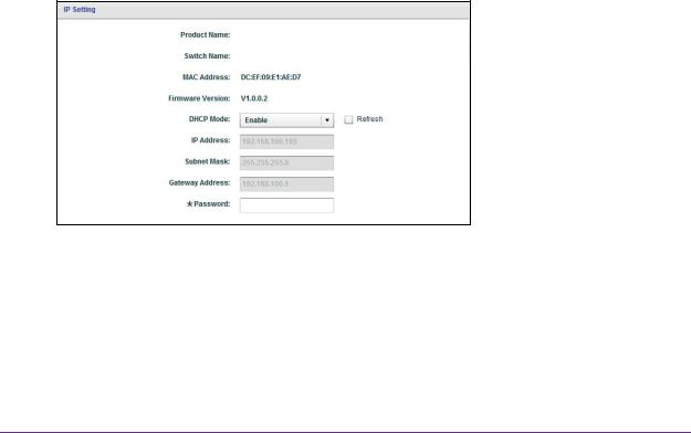
Specify IP Address Settings for the Switch |
from |
|
www |
|
|
|
|
|
By default, the switch IP address works as follows: |
. |
|
|
|
|
• If you cable the switch to a network with a DHCP server before you power on the switch, |
|
|
the DHCP server assigns an IP address to the switch when the switch is powered on. |
|
|
|
vandenborre |
|
• If you power on the switch when it is not connected to a network with a DHCP server, the |
. |
|
be |
||
switch uses its default IP address, which is 192.168.0.239.
You can disable the DHCP mode in the switch and enter static IP address and subnet mask values for the switch as well as the address of the gateway device used by the switch.
To specify IP address settings for a switch:
1. Connect your computer to the same network as the switch.
You can use a WiFi or wired network connection, or connect directly to a switch that is off-network using an Ethernet cable.
2.Launch the ProSAFE Plus Utility using the desktop icon or tile.
The Switch Selection page displays a list of Web Managed (Plus) switches that it discovers on the local network.
3.Select the switch.
If you do not see the switch, click the REFRESH button.
4.Click the IP SETTING button.
Note: To navigate to this page, select Network, select the switch, and click the IP SETTING button.
5.In the DHCP Mode menu, select Disable.
The IP Address, Subnet Mask, and Gateway Address fields are enabled.
6.Enter the IP address, subnet mask, and if available, the gateway address.
Manage Network Settings
10
Downloaded |
||
NETGEAR ProSAFE Plus Configuration Utility |
|
|
7. Enter the switch’s password in the Password field. |
from |
|
www |
||
The switch’s default password is password. |
||
|
. |
|
8. Click the APPLY button. |
vandenborre |
|
|
||
Your settings are saved. |
|
|
Manage Multicast Traffic With IGMP Snooping |
. |
|
be |
||
|
||
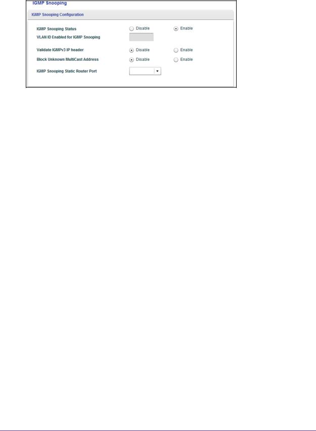
Internet Group Management Protocol (IGMP) snooping allows a switch to forward multicast traffic intelligently on the switch. Multicast IP traffic is traffic that is destined to a host group. Host groups are identified by class D IP addresses, which range from 224.0.0.0 to 239.255.255.255. Based on the IGMP query and report messages, the switch forwards traffic only to the ports that request the multicast traffic. This feature prevents the switch from broadcasting the traffic to all ports and possibly affecting network performance.
The switch maintains a map that shows which links need which IP multicast streams. The switch forwards multicast traffic only to the links that requested them and cuts multicast traffic from links that do not contain a multicast listener. Essentially, IGMP snooping helps optimize multicast performance at Layer 2 and is especially useful for bandwidth-intensive IP multicast applications such as IPTV.
Customize IGMP Snooping
By default, IGMP snooping is enabled. You can customize the settings for your network.
To customize IGMP snooping:
1.Connect your computer to the same network as the switch.
You can use a WiFi or wired network connection, or connect directly to a switch that is off-network using an Ethernet cable.
2.Launch the ProSAFE Plus Utility using the desktop icon or tile.
The Switch Selection page displays a list of Web Managed (Plus) switches that it discovers on the local network.
3.Select the switch.
If you do not see the switch, click the REFRESH button.
4.Click the APPLY button.
You are asked to enter the password for the switch.
5.Enter the switch’s password in the password field. The switch’s default password is password.
The Switch Status page displays.
6.Select System > Multicast.
Manage Network Settings
11
NETGEAR ProSAFE Plus Configuration UtilityDownloaded
from
www . vandenborre . be
7.Select the IGMP Snooping Status Enable radio button.
8.(Optional) Select the Validate IGMPv3 IP header Enable radio button.
Some network devices might not conform to the IGMPv3 standard. When the Validate IGMPv3 IP header option is enabled, IGMP messages are required to include TTL = 1, ToS Byte = 0xC0 (Internetwork Control), and the router alert IP option (9404) must be set. Otherwise, the packets are ignored.
9.(Optional) Select the Block Unknown MultiCast Address Enable radio button.
When this feature is enabled, multicast packets are forwarded only to the ports that are in the multicast group learned from IGMP snooping. All unknown multicast packets are dropped.
10.(Optional, for some models only) Select an option from the IGMP Snooping Static Router Port menu.
You can select a port to be the dedicated IGMP snooping static router port if no IGMP query exists in the network for the switch to discover the router port dynamically. After a port is selected as the static router port, all IGMP Join and Leave reports are forwarded to the port.
11.Click the APPLY button. Your settings are saved.
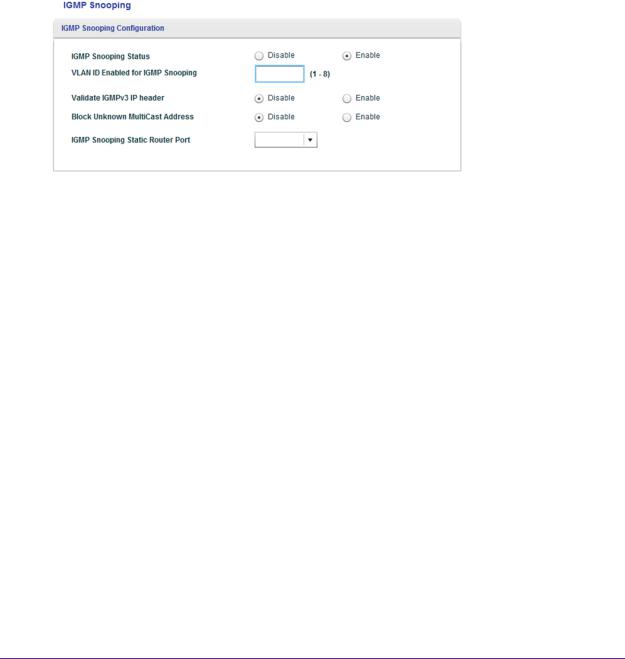
Specify a VLAN for IGMP Snooping
You can specify a VLAN for IGMP snooping only if you enabled port-based or 802.1Q-based VLANs (see Chapter 4, Use VLANS for Traffic Segmentation).
To specify a VLAN for IGMP snooping:
1.Connect your computer to the same network as the switch.
You can use a WiFi or wired network connection, or connect directly to a switch that is off-network using an Ethernet cable.
2.Launch the ProSAFE Plus Utility using the desktop icon or tile.
The Switch Selection page displays a list of Web Managed (Plus) switches that it discovers on the local network.
Manage Network Settings
12
|
|
|
Downloaded |
|
|
|
NETGEAR ProSAFE Plus Configuration Utility |
||
3. |
|
Select the switch. |
|
from |
|
|
www |
||
|
|
If you do not see the switch, click the REFRESH button. |
|
|
5. |
|
Enter the switch’s password in the password field. |
. |
|
|
|
vandenborre |
||
4. |
|
Click the APPLY button. |
|
|
|
You are asked to enter the password for the switch. |
|
|
|
|
|
|
. |
|
|
The switch’s default password is password. |
|
be |
|
|
|
|
||
|
The Switch Status page displays. |
|
|
|
6. |
|
Select System > Multicast. |
|
|
|
|
|
|
|
|
|
|
|
|
The previous figure is an example. Your switch might support more or less VLANs for IGMP snooping.
7.Make sure that the IGMP Snooping Status Enable radio button is selected.
8.In the VLAN ID Enabled for IGMP Snooping field, enter the ID of the VLAN.
By default, if you enable IGMP snooping, snooping occurs on VLAN 1. However, you can enable snooping on any VLAN:
•For port-based VLANs, you can enter a VLAN ID from 1 to the maximum number that you switch supports (5, 8, 16, or 24).
•For 802.1Q-based VLANs, you can enter a VLAN ID from 1 to 4094.
9.Click the APPLY button. Your settings are saved.
Set Up Static Link Aggregation Groups
Link aggregation groups (LAGs) allow you to combine multiple Ethernet links into a single logical link. Network devices treat the aggregation as if it were a single link, which increases fault tolerance and load sharing. The number of LAGs that the switch supports depends on the model. Configure LAG membership before you enable the LAG.
Manage Network Settings
13

|
Downloaded |
|
|
|
NETGEAR ProSAFE Plus Configuration Utility |
|
|
|
from |
||
Note: Static link aggregation (port trunking) is supported on the following |
www |
||
models: |
|||
. |
|||
• |
GS110EMX |
||
vandenborre |
|||
• |
GS116Ev2 |
||
|
|||
• |
GS408EPP |
|
|
• |
GS750E |
. |
|
• |
GSS108EPP |
be |
|
|
|||
• |
GSS116E |
|
|
• |
JGS516PE |
|
|
• JGS524Ev1 (requires firmware v1.00.15 or a later version) |
|
||
• |
JGS524Ev2 |
|
|
• |
JGS524PE |
|
|
• |
XS512EM |
|
|
• |
XS708E |
|
|
• |
XS708Ev2 |
|
|
• |
XS716E |
|
|
• |
XS724EM |
|
|
Note: In addition to static link aggregation (port trunking), models GS110EMX, GS750E, XS512EM, and XS724EM also support IEEE 802.3ad Link Aggregation and Link Aggregation Control Protocol (LACP) groups.
You must set up LAG membership before you can enable LAGs.
To specify LAG membership and enable a LAG:
1.Connect your computer to the same network as the switch.
You can use a WiFi or wired network connection, or connect directly to a switch that is off-network using an Ethernet cable.
2.Launch the ProSAFE Plus Utility using the desktop icon or tile.
The Switch Selection page displays a list of Web Managed (Plus) switches that it discovers on the local network.
3.Select the switch.
If you do not see the switch, click the REFRESH button.
4.Click the APPLY button.
You are asked to enter the password for the switch.
5.Enter the switch’s password in the password field. The switch’s default password is password.
Manage Network Settings
14

|
|
Downloaded |
||
|
|
NETGEAR ProSAFE Plus Configuration Utility |
|
|
|
The Switch Status page displays. |
from |
||
|
www |
|||
6. |
Select System > LAG > LAG Membership. |
|||
|
|
|
|
. |
|
|
|
|
vandenborre |
|
|
|
|
|
|
|
|
|
. |
|
|
|
|
be |
|
|
|
|
|
|
The previous figure is an example. Your switch might provide a larger number of ports. |
|||
7. |
In the LAG ID menu, select the LAG ID. |
|
||
|
The number of LAGs that the switch supports depends on the model. |
|
||
8. |
Select the ports for the LAG by selecting the associated check boxes under the port |
|||
|
numbers. |
|
||
|
A LAG consists of at least two ports. |
|
||
9. |
Click the APPLY button. |
|
||
|
Your settings are saved. |
|
||
10. Select System > LAG.
11.Select the ID of the LAG for which you just set up the port membership.
12.In the Admin Mode menu, select Enable.
13.Click the APPLY button. Your settings are saved.
Manage Network Settings
15

3.Optimize Performance With Quality of Service
Downloaded |
|
from |
|
www |
|
. |
|
vandenborre |
|
3 |
. |
|
be |
This chapter covers the following topics:
•Enable 802.1p/DSCP-Based Quality of Service
•Configure Port-Based Quality of Service
•Set Up Rate Limiting
•Set Up Broadcast Filtering
16
Loading...