


 Loading...

Start Here
The NETGEAR™ Model FS516 16-Port Fast Ethernet Switch and Model FS524 24-Port Fast Ethernet Switch provide you with a low-cost, high-performance network solution and are designed to support power workgroups operating at either 10 megabits per second (Mbps) or 100 Mbps.
Ethernet switches provide private, dedicated, 10 Mbps (or 100 Mbps) capacity to each connected PC/server or hub/workgroup segment, which is significantly higher than in a shared environment. The higher bandwidth enables the use of applications such as multimedia, imaging, video, or high-performance clientserver functions among users who are spread out over the network.
With both the Model FS516 switch and the Model FS524 switch, improvement is accomplished very easily, with no change to the desktop (the network interface cards or software and the network wiring). As a result, the performance upgrade and the applications it enables are obtained very quickly and at a low cost.
Features
The Model FS516 and Model FS524 switches have the following key features:
•Sixteen (Model FS516) or twenty-four (Model FS524) automatic speedsensing (autosensing) 10/100 Mbps Ethernet ports to provide fast information exchange, resource sharing, and client or peer-to-peer communication using simple Category 5 unshielded twisted pair (UTP) cable
•Automatic address learning function to build the packet-
forwarding information table
The table contains up to 4,000 MAC addresses for the Model FS516 and up to 8,000 MAC addresses for the Model FS524 (that is, the switch can support networks with as many as 8,000 devices).
•Switch-selectable autonegotiating or full-duplex mode of operation
Full-duplex mode doubles throughput of point-to-point connections by letting individual ports transmit and receive concurrently when the other end also supports full-duplex mode. The default is half-duplex if the connected device does not support N-way negotiation. The duplex toggle switch can be set to full-duplex if the connected port is operating at fullduplex mode.
•Wire-speed filtering and forwarding to provide “traffic cop” function by directing traffic to the appropriate route without slowing down the traffic
Store-and-forward forwarding node to minimize erroneous packets on the network
•Half-duplex backpressure
•Easy Plug-and-Play installation with no software to configure, which saves time and minimizes the potential for configuration errors
Model FS516/FS524 Fast Ethernet Switch Installation Guide
•Normal/Uplink push button to simplify network extension
The switch can be connected to a hub using a simple, straight-through cable.
•Protocol independence and compatibility with all common protocols such as TCP/IP, NetWare, DECnet, and Microsoft Networks
•Vista RJ-45 network ports with built-in LEDs to monitor individual port status
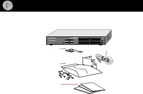
Package Contents
Model FS516 or Model FS524 switch (Model FS516 shown)
Auto 10/100 Mbps |
|
FS516 |
10/100 Mbps |
|
|
16PORT |
|
|
Fast Ethernet Switch |
1 |
8 |
Utilization% |
Link FDX |
Link FDX |
10/100 Mbps |
|
Normal/Uplink |
Power |
|
|
Utilization% |
13 |
16 |
Rubber |
|
AC |
|
power |
|
footpads |
|
cord |
Rack mount kit
Installation guide,
Warranty & Owner
Registration Card,
Support Information Card
9191FA
Verify that your package contains the following:
•Model FS516 or Model FS524 switch
•Rubber footpads for tabletop installation
•This installation guide
•Rack mount kit for 19-inch rack installation
•Warranty & Owner Registration Card
•Support Information Card
•Power cord
Model FS516/FS524 Fast Ethernet Switch Installation Guide

Product Illustration
Front Panel
The front panel of the Model FS516/FS524 switch contains the following LEDs that correspond to each network port located on the hub: Rx/Tx/Collision and 100 Mbps. Each vista RJ-45 network port has its own Link LED (located at the top left corner of each 10/100 Mbps port), and full-duplex (FDX) LED (located at the top right corner of each 10/100 Mbps port).
Front Panel of the Model FS516 Switch
Auto 10/100 Mbps
MODEL FS516
10/100 Mbps
16PORT
10/100Mbps Fast Ethernet Switch |
|
|
|
|
|
|
|
|
|
|
|
|
|
|
|
1 |
|
|
|
|
|
|
|
|
|
|
|
|
|
|
|
|
|
|
|
|
|
8 |
|
|
||||
|
|
|
|
|
|
|
|
|
|
Utilization% |
|
|
|
|
|
|
Link |
|
FDX |
|
Link |
|
FDX |
|
|
|||||||||||||||||||
|
|
Power |
|
|
|
|
|
10/100 Mbps |
|
|
|
|
|
|
|
|
|
|
|
|
|
|
|
|
|
|
|
|
|
|
|
|
|
|
|
Normal/Uplink |
||||||||
|
|
|
|
|
|
|
|
|
|
|
|
|
|
|
|
|
|
|
|
|
|
|
|
|
|
|
|
|
|
|
|
|
|
|
|
|
|
|
|
|
|
|||
|
|
|
|
|
|
|
|
|
|
|
|
|
|
|
|
|
|
|
|
|
|
|
|
|
|
|
|
|
|
|||||||||||||||
|
|
|
|
|
|
|
|
|
|
|
|
|
|
|
|
|
|
|
|
|
|
|
|
|
|
|
|
|
|
|
|
|
|
|
|
|
|
|
|
|
|
|
|
|
|
|
|
|
|
|
|
|
|
|
Utilization% |
13 |
|
|
|
|
|
|
|
|
|
|
|
|
|
|
|
|
|
|
|
|
|
16 |
|
|
|||||||||
|
|
|
|
|
|
|
|
|
|
|
|
|
|
|
|
|
|
|
|
|
|
|
|
|
|
|
|
|
|
|
|
|
|
|
|
|
|
|
|
|
|
|
|
|
|
|
|
|
|
|
|
|
|
|
|
|
|
|
|
|
|
|
|
|
|
|
|
|
|
|
|
|
|
|
|
|
|
|
|
|
|
|
|
|
|
|
|
|
|
Front Panel of the Model FS524 Switch
100 Mbps |
LEDs |
Auto 10/100 Mbps |
10/100 Mbps |
24PORT |
10/100Mbps Fast Ethernet Switch |
Utilization% |
10/100 Mbps |
Power |
Utilization% |
Power LED
10/100 Mbps ports
|
|
|
MODEL FS524 |
1 |
|
|
12 |
Link |
FDX |
Link |
FDX |
|
|
|
Normal/Uplink |
13 |
|
|
24 |
Rx/Tx |
|
Normal/Uplink |
|
||
Collision LEDs |
|
push button |
|
|
9189FA |
Model FS516/FS524 Fast Ethernet Switch Installation Guide

LEDs
The table below describes the activity of the LEDs.
Label |
Color |
Activity |
Description |
|
|
|
|
Pwr (Power) |
Green |
On |
Power is supplied to the switch. |
|
|
Off |
Power is disconnected. |
|
|
|
|
Rx/Tx/Collision |
Green |
Blinking |
Packet transmission or reception is occurring |
|
|
|
on the port. The blinking action corresponds to |
|
|
|
the number of packets that are transmitted or |
|
|
|
received. |
|
Yellow |
Blinking |
Data collisions are occurring on the port. The |
|
|
|
blinking corresponds to the number of |
|
|
|
collisions. When a collision occurs, the |
|
|
|
connected device pauses and transmits again |
|
|
|
after waiting a specified time. |
|
|
|
|
100 Mbps |
Green |
On |
The port is operating in 100 Mbps mode. |
|
|
Off |
The port is operating in 10 Mbps mode. |
|
|
|
|
Link |
Green |
On |
A valid link is established on the port. |
|
|
Off |
A link is not established on the port. |
|
|
|
|
FDX |
Green |
On |
The port is operating in full-duplex mode. |
|
|
Off |
The port is operating in half-duplex mode. |
|
|
|
|
Vista RJ-45 Network Ports with Built-in LEDs
All of the ports on the switch are 10/100 Mbps capable autosensing Ethernet ports. Each port supports only unshielded twisted pair (UTP) cable using an 8- pin RJ-45 plug. Each port uses vista RJ-45 connectors that have two LEDs—the Link LED and the FDX LED.
Link FDX
8923EB
Normal/Uplink Push Button
The Normal/Uplink push button on the front panel of the switch allows you to select uplink (MDI) or normal (MDI-X) wiring for port 16 on the Model FS516 switch and port 24 on the Model FS524 switch. These ports are configured for normal wiring to connect to a PC when the push button is in the out position. When the push button is pressed in, these ports are configured for uplink wiring to connect to another switch or to a hub, using a straight-through twisted pair cable.
Model FS516/FS524 Fast Ethernet Switch Installation Guide
Loading...