


)NSTALLATION 'UIDE
ProSafe® Plus 8-port Gigabit Switch GS108E
Contents
English 1 Deutsch 7 Français 13
Русский 19
NETGEAR, Inc.
350 East Plumeria Drive
San Jose, CA 95135
version 1.0

English
)NSTALLATION 'UIDE
ProSafe® Plus 8-port Gigabit Switch GS108E
Start Here
Estimated Installation Time: 5–10 minutes
Unpack the Box and Verify the Contents
When you open the box, verify that you received everything. The package includes:
•ProSafe® Plus 8-port Gigabit Switch GS108
•AC power adapter
•Wall-mounting screws
•Installation Guide (this document)
•Resource CD (contains switch configuration software)
If you don't have everything listed above, get contact information at www.NETGEAR.com in the Support area.
Prepare to Install the Switch
Decide where you want to place the switch. Find a flat horizontal surface such as a table, desk or shelf. The switch comes with wall-mounting screws. You can use the screws if you want to hang the switch in an open space on a wall. Make sure the selected location is:
•Not in direct sunlight or near a heater or heating vent.
•Not cluttered or crowded. There should be at least 2 inches (5 cm) of clear space on all sides of the switch.
•Well ventilated (especially if it is in a closet).
Also, you will need one Category 5e (Cat 5e) Ethernet cable with RJ-45 connectors for each device you want to connect to the switch. Each Ethernet cable must be less than 328 feet (100 meters).
Install the Switch and Connect the Other Devices
1.Place the switch on a flat surface or hook onto the screws.
1

English
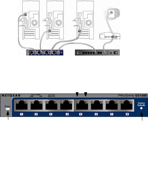
2.For each device, insert one end of an Ethernet cable into the port in the device and insert the other end into one of the Ethernet ports on the switch.
Modem
GS108E |
Firewall |
|
ProSafe® Plus Switch |
||
|
3.Connect the power adapter cord into the back of the switch and then plug the adapter into a power source (such as a wall socket or power strip).
4.The Power light should light up.
100 MbpsLED |
|
|
|
|
|
10 Mbps LED |
Power |
Both LEDs light for a |
Reset |
|
1000 Mbps connection |
|
5.Check the LEDs to confirm that all connections are correct.
LED |
Activity |
|
|
|
|
Power |
• |
On: Switch has power. |
|
• |
Off: No power. |
|
|
|
RJ-45 ports |
• |
Right LED on: 10 Mbps connection to a powered device. |
|
• |
Left LED on: 100 Mbps connection to a powered device. |
|
• |
Both LEDs on: 1000 Mbps connection to a powered |
|
|
device. |
|
• |
Blink: Activity on this port. |
|
|
|
2
English
Set Up the Switch Configuration Utility
In order to make use of the switch’s enhanced features you can install and use a switch configuration utility. This utility is on the Resource CD shipped with the switch.
Note: The configuration utility is installed on your PC and is only supported on MS Windows.
Install the Configuration Utility
To install the ProSafe® Plus Switch Configuration Utility:
1.Insert the Resource CD into a PC connected to the switch.
2.Click on Install ProSafe Plus Utility and follow the prompts to install the program. The switch configuration utility will be installed in the program directory of your PC and a ProSafe Plus Utility icon will be placed on your desktop.
Configure the Switch
To configure the switch to use enhanced features:
1.Double click the ProSafe Plus Utility icon. The configuration home screen displays.
2.The configuration utility displays a list of enhanced switches it discovers on the local network. Select the switch you want to configure.
3.You will be asked to enter the password for the switch. The default is “password”.
4.Enter the desired switch configuration. Refer to the ProSafe® Plus Switch Configuration Utility User Guide for a description of enhanced features. The user guide can be accessed by links on the Help tab of the utility or on the
Resource CD.
3

|
English |
Specifications |
|
|
|
|
Technical Specifications |
|
|
Standards |
IEEE 802.3i 10BASE-T Ethernet, IEEE 802.3u 100BASE-TX |
compatibility |
Fast Ethernet, IEEE 802.3ab 1000 BASE-T, IEEE 802.3x Flow |
|
Control, IEEE 802.1p and TOS priority, WRR queuing |
|
|
Network interface |
RJ-45 connector for 10BASE-T, 100BASE-TX, or 1000BASE-T |
|
|
Power Adapter |
12V @ 1.0A DC input |
|
|
Power Consumption |
4W max |
|
|
Weight |
0.522 Kg (1.15 lbs) |
|
|
Dimensions |
158 mm x 105 mm x 27 mm |
(W x D x H) |
6.2 in x 4.1 in x 1.1 in |
|
|
Operating |
0 to 50°C (32 to 122°F) |
temperature |
|
|
|
Operating humidity |
10% t0 90% relative humidity, non-condensing |
|
|
Electromagnetic |
CE Class B, included EN55022 (CISPR 22) and EN55024, |
compliance |
FCC part 15 Class B, VCCI Class B, C-Tick Class B |
|
|
Power adapter safety |
CE mark, Commercial UL listed (UL 60950-1), C-Tick, CB |
agency approvals |
|
|
|
4

|
|
English |
|
|
|
|
|
Performance Specifications |
|
|
|
Frame filter rate |
|
14800 frames/sec max for 10M port; 148,800 frames/sec max |
|
|
for 100M; 1,488,000 frames/sec max for 1000M port |
|
|
|
Frame forward rate |
|
14,800 frames/sec max for 10M port; 148,800 frames/sec max |
|
|
for 100M port; 1,488,000 frames/sec max for 1000M port |
|
|
|
Network latency |
|
1000 Mbps to 1000 Mbps: 2.7 μs max. |
(using 64-byte |
|
|
packets) |
|
|
|
|
|
Address database size |
up to 4K MAC addresses |
|
|
|
|
MAC Address |
|
Automatically updated |
Learning |
|
|
|
|
|
Queue buffer |
|
192 KB |
|
|
|
NETGEAR Green |
|
Auto power-down mode saves energy when ports are unused |
features |
|
|
|
|
|
Troubleshooting Tips |
||
|
|
|
Problem |
Action |
|
|
|
|
Power light is not lit |
The switch has no power. Make sure that: |
|
|
• |
The power cord is properly connected to the switch. |
|
• |
The power adapter is properly connected to a functioning |
|
|
power outlet. If it is in a power strip, make sure the power strip |
|
|
is turned on. If the socket is controlled by a light switch, make |
|
|
sure the switch is in the on position. |
|
• You are using the NETGEAR power adapter supplied with your |
|
|
|
switch. |
|
|
|
Port number light is |
There is a hardware connection problem. |
|
not lit for a |
• |
Make sure the cable connectors are securely plugged in at the |
connected device, |
|
switch and the device. |
or stays on |
• |
Make sure the connected device is turned on. |
continuously |
• |
If the Ethernet cable is connected to a NIC or other Ethernet |
|
|
adapter, make sure the card or adapter is installed correctly |
|
|
and is working. |
|
• |
Make sure the cable is less than 328 feet (100 meters). |
|
|
|
5
English
Technical Support
Thank you for selecting NETGEAR products.
After installing your device, locate the serial number on the label of your product and use it to register your product at http://www.NETGEAR.com/register. Registration is required before you can use the telephone support service. Registration via our website is strongly recommended.
Go to http://kbserver.netgear.com for product updates and Web support.
For additional information about setting up, configuring, and using your 5-port Enhanced Switch, see the see the User Manual.
For complete DoC please visit the NETGEAR EU Declarations of Conformity website at: http://kb.netgear.com/app/answers/detail/a_id/11621/.
6

Deutsch
ProSafe® Plus 8-Port Gigabit Switch GS108E
Hier beginnen
Geschätzte Installationszeit: 5–10 Minuten.
Auspacken des Kartons und Überprüfen des Inhalts
Öffnen Sie den Karton und vergewissern Sie sich, dass alle Teile enthalten sind. Lieferumfang:
•ProSafe® Plus 8-Port Gigabit Switch GS108E
•Netzteil
•Schrauben für die Wandmontage
•Installationsanleitung (dieses Dokument)
•Ressourcen-CD (enthält Software zur Switch-Konfiguration)
Falls Teile fehlen, finden Sie im Support-Bereich unter www.netgear.com Kontaktinformationen.
Vorbereiten der Installation des Switches
Wählen Sie einen Standort für den Switch. Am besten eignen sich ebene, horizontale Flächen wie z. B. ein Tisch oder ein Regal. Im Lieferumfang des Switches sind Schrauben für die Wandmontage enthalten. Sie können den Switch mit Schrauben an der Wand anbringen. Vergewissern Sie sich, dass der Standort
•keinem direkten Sonnenlicht ausgesetzt ist und sich nicht in unmittelbarer Nähe eines Heizkörpers oder Heizlüfters befindet.
•genügend Platz bietet. An jeder Seite des Switches sollten mindestens 5 cm Platz sein.
•gut belüftet ist (vor allem, wenn er sich in einem Schrank befindet).
Für jedes Gerät, das an den Switch angeschlossen werden soll, ist ein Netzwerkkabel (Kategorie 5e) mit RJ-45-Steckern erforderlich. Die Netzwerkkabel dürfen nicht länger als 100 Meter sein.
Installieren des Switches und Anschließen der anderen Geräte
1.Stellen Sie den Switch auf eine ebene Fläche oder hängen Sie ihn an die Wandschrauben.
7
Deutsch
2.Schließen Sie die Netzwerkkabel an die Netzwerkanschlüsse der Geräte und an einen Port des Switches an.
Modem
GS108E |
Firewall |
|
ProSafe® Plus Switch |
||
|
3.Stecken Sie das Stromkabel in den Anschluss an der Rückseite des Switches und schließen Sie das Gerät an einer Steckdose an.
4.Die Stromanzeige sollte aufleuchten.
100 MBit/s LED |
|
|
|
|
|
10 MBit/s LED |
Strom |
Beide LEDs zeigen eine |
Reset |
|
1.000-MBit/s-Verbindung |
|||
|
|
5.Überprüfen Sie anhand der LEDs, ob alle Anschlüsse funktionieren.
LED |
Aktivität (Fortsetzung) |
|
|
|
|
Strom |
• |
An: Es besteht Stromzufuhr zum Switch. |
|
• |
Aus: Keine Stromzufuhr. |
|
|
|
RJ-45- |
• |
Rechte LED ein: 10-MBit/s-Verbindung zu einem |
Anschlüsse |
|
angeschlossenen Gerät. |
|
• |
Linke LED an: 100-MBit/s-Verbindung zu einem |
|
|
angeschlossenen Gerät. |
|
• |
Beide LEDs an: 1.000-MBit/s-Verbindung zu einem |
|
|
angeschlossenen Gerät. |
|
• |
Blinken: Aktivität an diesem Port. |
|
|
|
8
 Loading...