


8-Port Multi-Gigabit Smart Managed Pro Switch with Two 10G Ports
MS510TX and MS510TXPP
User Manual
September 2017 202-11762-02
350 East Plumeria Drive
San Jose, CA 95134
USA

Smart Managed Pro Switches MS510TX and MS510TXPP
Support
Thank you for purchasing this NETGEAR product. You can visit www.netgear.com/support to register your product, get help, access the latest downloads and user manuals, and join our community. We recommend that you use only official NETGEAR support resources.
Conformity
For the current EU Declaration of Conformity, visit http://kb.netgear.com/app/answers/detail/a_id/11621.
Compliance
For regulatory compliance information, visit http://www.netgear.com/about/regulatory.
See the regulatory compliance document before connecting the power supply.
Trademarks
© NETGEAR, Inc., NETGEAR and the NETGEAR Logo are trademarks of NETGEAR, Inc. Any non-NETGEAR trademarks are used for reference purposes only.
Revision History
Publication Part Number |
Publish Date |
Comments |
|
|
|
202-11762-02 |
September 2017 |
Made minor changes and corrections. |
|
|
|
202-11762-01 |
September 2017 |
First publication. |
|
|
|
2

Contents
Chapter 1 Get Started
Switch Descriptions. . . . . . . . . . . . . . . . . . . . . . . . . . . . . . . . . . . . . . . . . . . . . . . . . . 10 Available Publications . . . . . . . . . . . . . . . . . . . . . . . . . . . . . . . . . . . . . . . . . . . . . . . . 10 Switch Management Methods. . . . . . . . . . . . . . . . . . . . . . . . . . . . . . . . . . . . . . . . . 10 Web Browser Requirements and Supported Browsers . . . . . . . . . . . . . . . . . . . . 11 User-Defined Fields . . . . . . . . . . . . . . . . . . . . . . . . . . . . . . . . . . . . . . . . . . . . . . . . . 11 Interface Naming Conventions . . . . . . . . . . . . . . . . . . . . . . . . . . . . . . . . . . . . . . . . 12 Access the Switch . . . . . . . . . . . . . . . . . . . . . . . . . . . . . . . . . . . . . . . . . . . . . . . . . . . 12
Access the Switch On-Network With a DHCP Server. . . . . . . . . . . . . . . . . . . 13 Access the Switch On-Network Without a DHCP Server. . . . . . . . . . . . . . . . 15 Access the Switch Off-Network. . . . . . . . . . . . . . . . . . . . . . . . . . . . . . . . . . . . . 16 Register the Switch . . . . . . . . . . . . . . . . . . . . . . . . . . . . . . . . . . . . . . . . . . . . . . . . . . 17 How to Configure Interface Settings . . . . . . . . . . . . . . . . . . . . . . . . . . . . . . . . . . . 17 Local Browser Interface Device View. . . . . . . . . . . . . . . . . . . . . . . . . . . . . . . . . . . 19
Chapter 2 Configure System Information
View and Configure the Switch Management Settings . . . . . . . . . . . . . . . . . . . . 24 View or Define System Information and View Software Versions . . . . . . . . 24 View the System CPU Status. . . . . . . . . . . . . . . . . . . . . . . . . . . . . . . . . . . . . . . . 26 View USB Device Information . . . . . . . . . . . . . . . . . . . . . . . . . . . . . . . . . . . . . . . 27 Configure the IPv4 Address for the Network Interface and
Management VLAN . . . . . . . . . . . . . . . . . . . . . . . . . . . . . . . . . . . . . . . . . . . . . . . 28 Configure the IPv6 Address for the Network Interface . . . . . . . . . . . . . . . . . 30 View the IPv6 Network Neighbor. . . . . . . . . . . . . . . . . . . . . . . . . . . . . . . . . . . . 31 Configure the Time Settings . . . . . . . . . . . . . . . . . . . . . . . . . . . . . . . . . . . . . . . . 32 Configure DNS Settings . . . . . . . . . . . . . . . . . . . . . . . . . . . . . . . . . . . . . . . . . . . . 41 Configure Green Ethernet Settings . . . . . . . . . . . . . . . . . . . . . . . . . . . . . . . . . . 45
Use the Device View . . . . . . . . . . . . . . . . . . . . . . . . . . . . . . . . . . . . . . . . . . . . . . . . . 50 Configure Power over Ethernet . . . . . . . . . . . . . . . . . . . . . . . . . . . . . . . . . . . . . . . 50 PoE Overview . . . . . . . . . . . . . . . . . . . . . . . . . . . . . . . . . . . . . . . . . . . . . . . . . . . . 51 Device Class Power Requirements . . . . . . . . . . . . . . . . . . . . . . . . . . . . . . . . . . . 51 Power Allocation and Power Budget . . . . . . . . . . . . . . . . . . . . . . . . . . . . . . . . . 52 Configure the Global PoE Settings . . . . . . . . . . . . . . . . . . . . . . . . . . . . . . . . . . . 53 Manage and View the PoE Port Configuration . . . . . . . . . . . . . . . . . . . . . . . . . 55 Configure SNMP . . . . . . . . . . . . . . . . . . . . . . . . . . . . . . . . . . . . . . . . . . . . . . . . . . . . 57 Configure the SNMPv1/v2 Community . . . . . . . . . . . . . . . . . . . . . . . . . . . . . . 58 Configure SNMPv1/v2 Trap Settings . . . . . . . . . . . . . . . . . . . . . . . . . . . . . . . . 60 Configure SNMPv1/v2 Trap Flags . . . . . . . . . . . . . . . . . . . . . . . . . . . . . . . . . . . 62 View the Supported MIBs . . . . . . . . . . . . . . . . . . . . . . . . . . . . . . . . . . . . . . . . . . 63
3

Smart Managed Pro Switches MS510TX and MS510TXPP
Configure SNMPv3 Users . . . . . . . . . . . . . . . . . . . . . . . . . . . . . . . . . . . . . . . . . . 64 Configure LLDP . . . . . . . . . . . . . . . . . . . . . . . . . . . . . . . . . . . . . . . . . . . . . . . . . . . . . 65 Configure LLDP Global Settings . . . . . . . . . . . . . . . . . . . . . . . . . . . . . . . . . . . . . 65 Configure LLDP Port Settings. . . . . . . . . . . . . . . . . . . . . . . . . . . . . . . . . . . . . . . 67 LLDP-MED Network Policy. . . . . . . . . . . . . . . . . . . . . . . . . . . . . . . . . . . . . . . . . 68 LLDP-MED Port Settings. . . . . . . . . . . . . . . . . . . . . . . . . . . . . . . . . . . . . . . . . . . 69 Local Information . . . . . . . . . . . . . . . . . . . . . . . . . . . . . . . . . . . . . . . . . . . . . . . . . 70 Neighbors Information . . . . . . . . . . . . . . . . . . . . . . . . . . . . . . . . . . . . . . . . . . . . . 72 Configure DHCP Snooping. . . . . . . . . . . . . . . . . . . . . . . . . . . . . . . . . . . . . . . . . . . . 75 Configure the Global DHCP Snooping Settings . . . . . . . . . . . . . . . . . . . . . . . . 76 Enable DHCP for All Interfaces in a VLAN . . . . . . . . . . . . . . . . . . . . . . . . . . . . . 77 Configure DHCP Snooping Interface Settings . . . . . . . . . . . . . . . . . . . . . . . . . 77 Configure Static DHCP Bindings. . . . . . . . . . . . . . . . . . . . . . . . . . . . . . . . . . . . . 78 Configure the DHCP Snooping Persistent Settings . . . . . . . . . . . . . . . . . . . . . 80 Set Up PoE Timer Schedules . . . . . . . . . . . . . . . . . . . . . . . . . . . . . . . . . . . . . . . . . . 80 Create a PoE Timer Schedule . . . . . . . . . . . . . . . . . . . . . . . . . . . . . . . . . . . . . . . 81 Specify the Settings for a PoE Timer Schedule . . . . . . . . . . . . . . . . . . . . . . . . 82 Add a Periodic Schedule for a PoE Timer Schedule . . . . . . . . . . . . . . . . . . . . . 83 Delete a Periodic Schedule for a PoE Timer Schedule. . . . . . . . . . . . . . . . . . . 84 Delete a PoE Timer Schedule. . . . . . . . . . . . . . . . . . . . . . . . . . . . . . . . . . . . . . . . 85
Chapter 3 Configure Switching
Configure Port Settings and Flow Control. . . . . . . . . . . . . . . . . . . . . . . . . . . . . . . 87 Configure IEEE 802.3x Global Flow Control. . . . . . . . . . . . . . . . . . . . . . . . . . . 87 Configure the Port Settings . . . . . . . . . . . . . . . . . . . . . . . . . . . . . . . . . . . . . . . . 88 Configure Link Aggregation Groups . . . . . . . . . . . . . . . . . . . . . . . . . . . . . . . . . . . . 89 Configure LAG Settings . . . . . . . . . . . . . . . . . . . . . . . . . . . . . . . . . . . . . . . . . . . . 90 Configure LAG Membership . . . . . . . . . . . . . . . . . . . . . . . . . . . . . . . . . . . . . . . . 92 Set the LACP System Priority . . . . . . . . . . . . . . . . . . . . . . . . . . . . . . . . . . . . . . . 93 Set the LACP Port Priority Settings . . . . . . . . . . . . . . . . . . . . . . . . . . . . . . . . . . 93 Configure VLANs . . . . . . . . . . . . . . . . . . . . . . . . . . . . . . . . . . . . . . . . . . . . . . . . . . . . 94 Configure VLAN Settings. . . . . . . . . . . . . . . . . . . . . . . . . . . . . . . . . . . . . . . . . . . 95 Configure VLAN Membership . . . . . . . . . . . . . . . . . . . . . . . . . . . . . . . . . . . . . . . 97 View VLAN Status. . . . . . . . . . . . . . . . . . . . . . . . . . . . . . . . . . . . . . . . . . . . . . . . . 99 Configure Port PVID Settings . . . . . . . . . . . . . . . . . . . . . . . . . . . . . . . . . . . . . . 100 Configure MAC-Based VLAN Groups . . . . . . . . . . . . . . . . . . . . . . . . . . . . . . . 102
Manually Add Members to or Remove Them From a MAC-Based
VLAN Group. . . . . . . . . . . . . . . . . . . . . . . . . . . . . . . . . . . . . . . . . . . . . . . . . . . . . 104 Configure Protocol-Based VLAN Groups . . . . . . . . . . . . . . . . . . . . . . . . . . . . 104 Manually Add Members to or Remove Them From a
Protocol-Based VLAN Group. . . . . . . . . . . . . . . . . . . . . . . . . . . . . . . . . . . . . . . 106 Configure GARP Switch Settings . . . . . . . . . . . . . . . . . . . . . . . . . . . . . . . . . . . 107 Configure GARP Ports . . . . . . . . . . . . . . . . . . . . . . . . . . . . . . . . . . . . . . . . . . . . 108 Configure a Voice VLAN . . . . . . . . . . . . . . . . . . . . . . . . . . . . . . . . . . . . . . . . . . . . . 110 Configure the Global Voice VLAN Settings . . . . . . . . . . . . . . . . . . . . . . . . . . . 110 Configure Membership for the Voice VLAN . . . . . . . . . . . . . . . . . . . . . . . . . . 111 Manage the OUI Table . . . . . . . . . . . . . . . . . . . . . . . . . . . . . . . . . . . . . . . . . . . . 112
4

Smart Managed Pro Switches MS510TX and MS510TXPP
Configure Auto-VoIP. . . . . . . . . . . . . . . . . . . . . . . . . . . . . . . . . . . . . . . . . . . . . . . . 114 Configure Spanning Tree Protocol. . . . . . . . . . . . . . . . . . . . . . . . . . . . . . . . . . . . . 115 Configure STP Settings . . . . . . . . . . . . . . . . . . . . . . . . . . . . . . . . . . . . . . . . . . . 116 Configure CST Settings . . . . . . . . . . . . . . . . . . . . . . . . . . . . . . . . . . . . . . . . . . . 118 Configure CST Port Settings . . . . . . . . . . . . . . . . . . . . . . . . . . . . . . . . . . . . . . . 120 View the CST Port Status. . . . . . . . . . . . . . . . . . . . . . . . . . . . . . . . . . . . . . . . . . 121 View Rapid STP Information . . . . . . . . . . . . . . . . . . . . . . . . . . . . . . . . . . . . . . . 123 Manage MST Settings . . . . . . . . . . . . . . . . . . . . . . . . . . . . . . . . . . . . . . . . . . . . 124 Configure MST Port Settings . . . . . . . . . . . . . . . . . . . . . . . . . . . . . . . . . . . . . . 126 View STP Statistics . . . . . . . . . . . . . . . . . . . . . . . . . . . . . . . . . . . . . . . . . . . . . . . 129 Configure Multicast. . . . . . . . . . . . . . . . . . . . . . . . . . . . . . . . . . . . . . . . . . . . . . . . . 129 View the MFDB Table . . . . . . . . . . . . . . . . . . . . . . . . . . . . . . . . . . . . . . . . . . . . . 130 View the MFDB Statistics . . . . . . . . . . . . . . . . . . . . . . . . . . . . . . . . . . . . . . . . . 132 Configure Auto-Video . . . . . . . . . . . . . . . . . . . . . . . . . . . . . . . . . . . . . . . . . . . . 132 IGMP Snooping Overview . . . . . . . . . . . . . . . . . . . . . . . . . . . . . . . . . . . . . . . . . 133 Configure the Global IGMP Snooping Settings. . . . . . . . . . . . . . . . . . . . . . . . 134 View the IGMP Snooping Table. . . . . . . . . . . . . . . . . . . . . . . . . . . . . . . . . . . . . 135 Configure IGMP Snooping for VLANs . . . . . . . . . . . . . . . . . . . . . . . . . . . . . . . 136 Modify IGMP Snooping Settings for a VLAN . . . . . . . . . . . . . . . . . . . . . . . . . 137 Disable IGMP Snooping on a VLAN and Remove It From the Table . . . . . . . 138 IGMP Snooping Querier Overview. . . . . . . . . . . . . . . . . . . . . . . . . . . . . . . . . . 138 Configure IGMP Snooping Querier. . . . . . . . . . . . . . . . . . . . . . . . . . . . . . . . . . 139 Configure IGMP Snooping Querier for VLANs . . . . . . . . . . . . . . . . . . . . . . . . 140 Display the IGMP Snooping Querier for VLAN Status . . . . . . . . . . . . . . . . . . 141 MLD Snooping Overview. . . . . . . . . . . . . . . . . . . . . . . . . . . . . . . . . . . . . . . . . . 142 Configure the Global MLD Snooping Settings . . . . . . . . . . . . . . . . . . . . . . . . 142 Configure MLD Snooping for a VLAN. . . . . . . . . . . . . . . . . . . . . . . . . . . . . . . . . . 143 Configure a Multicast Router Interface on a VLAN . . . . . . . . . . . . . . . . . . . . 144 Configure MLD Snooping Querier . . . . . . . . . . . . . . . . . . . . . . . . . . . . . . . . . . 145 Configure MLD Snooping Querier VLAN Settings . . . . . . . . . . . . . . . . . . . . . 146 Configure a Multicast Group . . . . . . . . . . . . . . . . . . . . . . . . . . . . . . . . . . . . . . . 147 Remove a Multicast Group . . . . . . . . . . . . . . . . . . . . . . . . . . . . . . . . . . . . . . . . 148 Configure Multicast Group Membership. . . . . . . . . . . . . . . . . . . . . . . . . . . . . 149 Configure the Multicast Forward All Option. . . . . . . . . . . . . . . . . . . . . . . . . . 150 View, Search, and Manage the MAC Address Table . . . . . . . . . . . . . . . . . . . . . . 151 View and Search the MAC Address Table . . . . . . . . . . . . . . . . . . . . . . . . . . . . 152 Change the Aging-Out Period of Dynamic MAC Addresses. . . . . . . . . . . . . 153 Add a Static MAC Address . . . . . . . . . . . . . . . . . . . . . . . . . . . . . . . . . . . . . . . . . 154 Remove a Static MAC Address . . . . . . . . . . . . . . . . . . . . . . . . . . . . . . . . . . . . . 154
Chapter 4 Configure Routing
IP Routing Overview . . . . . . . . . . . . . . . . . . . . . . . . . . . . . . . . . . . . . . . . . . . . . . . . 157
Configure IP Settings . . . . . . . . . . . . . . . . . . . . . . . . . . . . . . . . . . . . . . . . . . . . . . . 157
Configure the Routing Settings. . . . . . . . . . . . . . . . . . . . . . . . . . . . . . . . . . . . . 157
View the IP Statistics . . . . . . . . . . . . . . . . . . . . . . . . . . . . . . . . . . . . . . . . . . . . . 158
Configure VLAN Routing . . . . . . . . . . . . . . . . . . . . . . . . . . . . . . . . . . . . . . . . . . . . 161
Use the VLAN Static Routing Wizard . . . . . . . . . . . . . . . . . . . . . . . . . . . . . . . . 162
VLAN Routing Configuration . . . . . . . . . . . . . . . . . . . . . . . . . . . . . . . . . . . . . . . 163
5

Smart Managed Pro Switches MS510TX and MS510TXPP
Manage IPv4 Routes . . . . . . . . . . . . . . . . . . . . . . . . . . . . . . . . . . . . . . . . . . . . . . . . 164 Configure Address Resolution Protocol . . . . . . . . . . . . . . . . . . . . . . . . . . . . . . . . 166 Display the ARP Cache. . . . . . . . . . . . . . . . . . . . . . . . . . . . . . . . . . . . . . . . . . . . 167 Add an Entry to the ARP Table . . . . . . . . . . . . . . . . . . . . . . . . . . . . . . . . . . . . . 168 Configure the Global Aging-Out Time for ARP . . . . . . . . . . . . . . . . . . . . . . . 169 Remove an ARP Entry From the ARP Cache . . . . . . . . . . . . . . . . . . . . . . . . . . 170 Configure IPv6. . . . . . . . . . . . . . . . . . . . . . . . . . . . . . . . . . . . . . . . . . . . . . . . . . . . . 171 Configure IPv6 Global Settings. . . . . . . . . . . . . . . . . . . . . . . . . . . . . . . . . . . . . 171 Add a Static IPv6 Route . . . . . . . . . . . . . . . . . . . . . . . . . . . . . . . . . . . . . . . . . . . 172 Change the Preference for a Static IPv6 Route . . . . . . . . . . . . . . . . . . . . . . . 173 Remove a Static IPv6 Route . . . . . . . . . . . . . . . . . . . . . . . . . . . . . . . . . . . . . . . 174 View the IPv6 Route Table. . . . . . . . . . . . . . . . . . . . . . . . . . . . . . . . . . . . . . . . . 175 Configure IPv6 VLAN Interface Settings. . . . . . . . . . . . . . . . . . . . . . . . . . . . . 176 Add an IPv6 Global Address to an IPv6 VLAN . . . . . . . . . . . . . . . . . . . . . . . . 178 Change the Settings for an IPv6 Global Address on an IPv6 VLAN. . . . . . . 180 Remove an IPv6 Global Address From an IPv6 VLAN . . . . . . . . . . . . . . . . . . 181 Add an IPv6 Prefix for Advertisement on an IPv6 VLAN . . . . . . . . . . . . . . . 181
Change the Settings for an IPv6 Prefix for Advertisement on
an IPv6 VLAN. . . . . . . . . . . . . . . . . . . . . . . . . . . . . . . . . . . . . . . . . . . . . . . . . . . . 183 Remove an IPv6 Prefix From an IPv6 VLAN . . . . . . . . . . . . . . . . . . . . . . . . . . 183 View IPv6 Statistics for an Interface . . . . . . . . . . . . . . . . . . . . . . . . . . . . . . . . 184 View or Clear the IPv6 Neighbor Table . . . . . . . . . . . . . . . . . . . . . . . . . . . . . . 186
Chapter 5 Configure Quality of Service
Manage Class of Service . . . . . . . . . . . . . . . . . . . . . . . . . . . . . . . . . . . . . . . . . . . . 189 CoS Configuration. . . . . . . . . . . . . . . . . . . . . . . . . . . . . . . . . . . . . . . . . . . . . . . . 189 Configure Global CoS Settings . . . . . . . . . . . . . . . . . . . . . . . . . . . . . . . . . . . . . 190 Configure CoS Interface Settings for an Interface . . . . . . . . . . . . . . . . . . . . 190 Configure the Global CoS Queue Settings . . . . . . . . . . . . . . . . . . . . . . . . . . . 192 Configure the Global 802.1p to Queue Mapping . . . . . . . . . . . . . . . . . . . . . 193 DSCP to Queue Mapping . . . . . . . . . . . . . . . . . . . . . . . . . . . . . . . . . . . . . . . . . . 194
Manage Differentiated Services . . . . . . . . . . . . . . . . . . . . . . . . . . . . . . . . . . . . . . 195 DiffServ Overview . . . . . . . . . . . . . . . . . . . . . . . . . . . . . . . . . . . . . . . . . . . . . . . 196 View the Global DiffServ Resources . . . . . . . . . . . . . . . . . . . . . . . . . . . . . . . . 197 Specify DSCP Remark Values for Violate Action IP Packets. . . . . . . . . . . . . 197 Configure IPv4 DiffServ Classes . . . . . . . . . . . . . . . . . . . . . . . . . . . . . . . . . . . 199 Configure an IPv6 DiffServ IPv6 Classes . . . . . . . . . . . . . . . . . . . . . . . . . . . . 203 Configure a DiffServ Policy. . . . . . . . . . . . . . . . . . . . . . . . . . . . . . . . . . . . . . . . 207 Configure DiffServ Service Interfaces . . . . . . . . . . . . . . . . . . . . . . . . . . . . . . 212 View DiffServ Service Statistics. . . . . . . . . . . . . . . . . . . . . . . . . . . . . . . . . . . . 213
Chapter 6 Manage Device Security
Management Security Settings. . . . . . . . . . . . . . . . . . . . . . . . . . . . . . . . . . . . . . . 216 Change the Password. . . . . . . . . . . . . . . . . . . . . . . . . . . . . . . . . . . . . . . . . . . . . 216 Reset the Password to the Factory Default Value . . . . . . . . . . . . . . . . . . . . . 217 Configure RADIUS Servers . . . . . . . . . . . . . . . . . . . . . . . . . . . . . . . . . . . . . . . . 218 Configure TACACS+ Servers. . . . . . . . . . . . . . . . . . . . . . . . . . . . . . . . . . . . . . . 224
6

Smart Managed Pro Switches MS510TX and MS510TXPP
Configure Authentication Lists . . . . . . . . . . . . . . . . . . . . . . . . . . . . . . . . . . . . . 227 Configure Management Access. . . . . . . . . . . . . . . . . . . . . . . . . . . . . . . . . . . . . . . 230 Configure HTTP Settings . . . . . . . . . . . . . . . . . . . . . . . . . . . . . . . . . . . . . . . . . . 231 Configure HTTPS Settings . . . . . . . . . . . . . . . . . . . . . . . . . . . . . . . . . . . . . . . . . 231 Manage the Certificate . . . . . . . . . . . . . . . . . . . . . . . . . . . . . . . . . . . . . . . . . . . 233 Configure Access Control . . . . . . . . . . . . . . . . . . . . . . . . . . . . . . . . . . . . . . . . . 235 Configure Port Authentication . . . . . . . . . . . . . . . . . . . . . . . . . . . . . . . . . . . . . . . 241 Configure Global 802.1X Settings . . . . . . . . . . . . . . . . . . . . . . . . . . . . . . . . . . 241 Manage Port Authentication . . . . . . . . . . . . . . . . . . . . . . . . . . . . . . . . . . . . . . . 243 View the Port Summary. . . . . . . . . . . . . . . . . . . . . . . . . . . . . . . . . . . . . . . . . . . 245 View the Client Summary . . . . . . . . . . . . . . . . . . . . . . . . . . . . . . . . . . . . . . . . . 247 Set Up Traffic Control . . . . . . . . . . . . . . . . . . . . . . . . . . . . . . . . . . . . . . . . . . . . . . . 248 Configure Storm Control . . . . . . . . . . . . . . . . . . . . . . . . . . . . . . . . . . . . . . . . . . 248 Configure Port Security . . . . . . . . . . . . . . . . . . . . . . . . . . . . . . . . . . . . . . . . . . . 249 Configure Protected Ports. . . . . . . . . . . . . . . . . . . . . . . . . . . . . . . . . . . . . . . . . 252 Configure Private VLANs . . . . . . . . . . . . . . . . . . . . . . . . . . . . . . . . . . . . . . . . . . 252 Configure Access Control Lists . . . . . . . . . . . . . . . . . . . . . . . . . . . . . . . . . . . . . . . 258 Use the ACL Wizard to Create a Simple ACL. . . . . . . . . . . . . . . . . . . . . . . . . . 259 Configure a Basic MAC ACL. . . . . . . . . . . . . . . . . . . . . . . . . . . . . . . . . . . . . . . . 264 Configure MAC ACL Rules . . . . . . . . . . . . . . . . . . . . . . . . . . . . . . . . . . . . . . . . . 266 Configure MAC Bindings . . . . . . . . . . . . . . . . . . . . . . . . . . . . . . . . . . . . . . . . . . 270 View or Delete MAC ACL Bindings in the MAC Binding Table . . . . . . . . . . . 271 Configure an IP ACL . . . . . . . . . . . . . . . . . . . . . . . . . . . . . . . . . . . . . . . . . . . . . . 272 Configure Rules for a Basic IP ACL . . . . . . . . . . . . . . . . . . . . . . . . . . . . . . . . . . 274 Configure Rules for an Extended IP ACL . . . . . . . . . . . . . . . . . . . . . . . . . . . . . 277 Configure an IPv6 ACL . . . . . . . . . . . . . . . . . . . . . . . . . . . . . . . . . . . . . . . . . . . . 281 Configure IPv6 Rules . . . . . . . . . . . . . . . . . . . . . . . . . . . . . . . . . . . . . . . . . . . . . 283 Configure IP ACL Interface Bindings . . . . . . . . . . . . . . . . . . . . . . . . . . . . . . . . 286 View or Delete IP ACL Bindings in the IP ACL Binding Table. . . . . . . . . . . . . 288
Chapter 7 Monitor the System
Monitor the Switch and the Ports. . . . . . . . . . . . . . . . . . . . . . . . . . . . . . . . . . . . . 291
Switch Statistics . . . . . . . . . . . . . . . . . . . . . . . . . . . . . . . . . . . . . . . . . . . . . . . . . 291
View Port Statistics. . . . . . . . . . . . . . . . . . . . . . . . . . . . . . . . . . . . . . . . . . . . . . . 292
View Detailed Port Statistics. . . . . . . . . . . . . . . . . . . . . . . . . . . . . . . . . . . . . . . 295
View EAP Statistics . . . . . . . . . . . . . . . . . . . . . . . . . . . . . . . . . . . . . . . . . . . . . . . 298
Perform a Cable Test . . . . . . . . . . . . . . . . . . . . . . . . . . . . . . . . . . . . . . . . . . . . . 300
Configure and View Logs . . . . . . . . . . . . . . . . . . . . . . . . . . . . . . . . . . . . . . . . . . . . 301
Manage the Buffered Logs . . . . . . . . . . . . . . . . . . . . . . . . . . . . . . . . . . . . . . . . 302
Manage the Flash Log. . . . . . . . . . . . . . . . . . . . . . . . . . . . . . . . . . . . . . . . . . . . . 303
Manage the Server Log . . . . . . . . . . . . . . . . . . . . . . . . . . . . . . . . . . . . . . . . . . . 305
View the Trap Logs . . . . . . . . . . . . . . . . . . . . . . . . . . . . . . . . . . . . . . . . . . . . . . . 307
Configure Port Mirroring . . . . . . . . . . . . . . . . . . . . . . . . . . . . . . . . . . . . . . . . . . . . 308
View the System Resource Utilization . . . . . . . . . . . . . . . . . . . . . . . . . . . . . . . . . 309
Chapter 8 Maintain the Switch and Perform Troubleshooting
Reboot the Switch . . . . . . . . . . . . . . . . . . . . . . . . . . . . . . . . . . . . . . . . . . . . . . . . . . 312
7

Smart Managed Pro Switches MS510TX and MS510TXPP
Reset the Switch to Its Factory Default Settings . . . . . . . . . . . . . . . . . . . . . . . . 312 Export a File From the Switch . . . . . . . . . . . . . . . . . . . . . . . . . . . . . . . . . . . . . . . . 313 Export a File to the TFTP Server . . . . . . . . . . . . . . . . . . . . . . . . . . . . . . . . . . . 313 HTTP File Export . . . . . . . . . . . . . . . . . . . . . . . . . . . . . . . . . . . . . . . . . . . . . . . . . 315 Export a File From the Switch to a USB Device . . . . . . . . . . . . . . . . . . . . . . . 316 Download a File to the Switch . . . . . . . . . . . . . . . . . . . . . . . . . . . . . . . . . . . . . . . . 317 Download a File to the Switch Using TFTP . . . . . . . . . . . . . . . . . . . . . . . . . . . 317 Download a File to the Switch Using HTTP . . . . . . . . . . . . . . . . . . . . . . . . . . . 319 Download a File From a USB Device. . . . . . . . . . . . . . . . . . . . . . . . . . . . . . . . . 320 Manage Files. . . . . . . . . . . . . . . . . . . . . . . . . . . . . . . . . . . . . . . . . . . . . . . . . . . . . . . 321 Change the Image That Loads During the Boot Process. . . . . . . . . . . . . . . . 321 View the Dual Image Status . . . . . . . . . . . . . . . . . . . . . . . . . . . . . . . . . . . . . . . 322 Troubleshooting . . . . . . . . . . . . . . . . . . . . . . . . . . . . . . . . . . . . . . . . . . . . . . . . . . . . 323 Ping an IPv4 Address . . . . . . . . . . . . . . . . . . . . . . . . . . . . . . . . . . . . . . . . . . . . . 323 Ping an IPv6 Address . . . . . . . . . . . . . . . . . . . . . . . . . . . . . . . . . . . . . . . . . . . . . 325 Send an IPv4 Traceroute . . . . . . . . . . . . . . . . . . . . . . . . . . . . . . . . . . . . . . . . . . 326 Send an IPv6 Traceroute . . . . . . . . . . . . . . . . . . . . . . . . . . . . . . . . . . . . . . . . . . 327 Generate Technical Support Information . . . . . . . . . . . . . . . . . . . . . . . . . . . . 328 Enable Remote Diagnostics . . . . . . . . . . . . . . . . . . . . . . . . . . . . . . . . . . . . . . . . 329
Appendix A Configuration Examples
Virtual Local Area Networks (VLANs) . . . . . . . . . . . . . . . . . . . . . . . . . . . . . . . . . 331 VLAN Configuration Examples . . . . . . . . . . . . . . . . . . . . . . . . . . . . . . . . . . . . . 332 Access Control Lists (ACLs) . . . . . . . . . . . . . . . . . . . . . . . . . . . . . . . . . . . . . . . . . . 333 Sample MAC ACL Configuration. . . . . . . . . . . . . . . . . . . . . . . . . . . . . . . . . . . . 333 Sample Standard IP ACL Configuration . . . . . . . . . . . . . . . . . . . . . . . . . . . . . . 334 Differentiated Services (DiffServ) . . . . . . . . . . . . . . . . . . . . . . . . . . . . . . . . . . . . 335 Class . . . . . . . . . . . . . . . . . . . . . . . . . . . . . . . . . . . . . . . . . . . . . . . . . . . . . . . . . . . 336 DiffServ Traffic Classes . . . . . . . . . . . . . . . . . . . . . . . . . . . . . . . . . . . . . . . . . . . 336 Creating Policies . . . . . . . . . . . . . . . . . . . . . . . . . . . . . . . . . . . . . . . . . . . . . . . . . 337 DiffServ Example Configuration . . . . . . . . . . . . . . . . . . . . . . . . . . . . . . . . . . . 338 802.1X . . . . . . . . . . . . . . . . . . . . . . . . . . . . . . . . . . . . . . . . . . . . . . . . . . . . . . . . . . . 339 802.1X Example Configuration . . . . . . . . . . . . . . . . . . . . . . . . . . . . . . . . . . . . 341 MSTP . . . . . . . . . . . . . . . . . . . . . . . . . . . . . . . . . . . . . . . . . . . . . . . . . . . . . . . . . . . . . 342 MSTP Example Configuration . . . . . . . . . . . . . . . . . . . . . . . . . . . . . . . . . . . . . . 344 VLAN Routing Interface Configuration Example. . . . . . . . . . . . . . . . . . . . . . . . . 346
Appendix B Hardware Specifications and Default Settings
Hardware Specifications. . . . . . . . . . . . . . . . . . . . . . . . . . . . . . . . . . . . . . . . . . . . . 348
Switch Default Settings . . . . . . . . . . . . . . . . . . . . . . . . . . . . . . . . . . . . . . . . . . . . . 349
8

1. Get Started |
1 |
|
|
||
|
|
|
This manual describes how you can configure and monitor the following NETGEAR switches by using the local browser–based management interface:
•MS510TX. 8-Port Multi-Gigabit Smart Managed Pro Switch with two 10G Ports, Model MS510TX
•MS510TXPP. 8-Port Multi-Gigabit Smart Managed Pro Switch with PoE+ and two 10G Ports, Model MS510TXPP
This chapter contains the following sections:
•Switch Descriptions
•Available Publications
•Switch Management Methods
•Web Browser Requirements and Supported Browsers
•User-Defined Fields
•Interface Naming Conventions
•Access the Switch
•Register the Switch
•How to Configure Interface Settings
•Local Browser Interface Device View
In this manual, we refer to both switch models as the switch. Unless noted otherwise, all information applies to both switch models.
For more information about the topics covered in this manual, visit the support website at netgear.com/support.
Firmware updates with new features and bug fixes are automatically made available through the Insight app and, if selected, pushed straight from the cloud to the device. If you are not using the Insight app to manage your device, you can manually download and install the latest firmware by visiting downloadcenter.netgear.com. If the features or behavior of your product does not match what is described in this manual, you might need to update your firmware.
9

Smart Managed Pro Switches MS510TX and MS510TXPP
Switch Descriptions
The switch provides four multispeed Gigabit Ethernet and four 1G Ethernet RJ-45 copper ports with one dedicated 10G RJ-45 copper uplink port and one dedicated SFP+ fiber uplink port that supports 10G and 1G. Two of the four multispeed ports support 5G, 2.5G, and 1G. The other two multispeed ports support 2.5G and 1G. (The 10G RJ-45 copper uplink port also supports 5G, 2.5G and 1G.)
The switch models differ in the following ways:
•Model MS510TXPP. This model supports Power over Ethernet plus (PoE+) on all four multispeed ports and four 1G ports so that you can let the switch provide power to PoE-capable devices such as WiFi access points, VoIP phones, and IP security cameras.
•Model MS510TXPP. This model can supply up to 30W PoE+ (IEEE 802.3at) to each port, with a maximum PoE power budget of 180W across all active PoE+ ports.
Available Publications
The following guides and manual are available at downloadcenter.netgear.com:
•Installation Guide
•Hardware Installation Guide
•Smart Control Center User Manual
For general switch information, see the NETGEAR knowledge base articles at netgear.com/support.
Switch Management Methods
If you prefer, you can use the switch as a plug-and-play device, so you do not need to set up a custom configuration. Just connect power, connect to your network and to your other devices, and you are done.
You can configure the switch and the network, including the ports, the management VLAN, VLANs for traffic control, link aggregation for increased bandwidth, quality of service (QoS) for prioritizing traffic, and network security.
You can configure and monitor the switch by using one of the following methods:
•Smart Control Center (SCC). Initial discovery of the switch on the network requires the Smart Control Center (SCC) program, which runs on a Windows-based computer and is included on the resource CD. You can also download the SCC program from downloadcenter.netgear.com. If you do not use a Windows-based computer, get the IP address of the switch from the DHCP server in the network or use an IP scanner utility.
After discovery, you can configure the switch using the local browser–based management interface, or the SCC program for very basic setup. For more information, see Access the Switch on page 12 and the SCC user manual, which you can download from downloadcenter.netgear.com.
Get Started
10
Smart Managed Pro Switches MS510TX and MS510TXPP
•Local browser–based management interface. This manual describes how to use the local browser–based management interface, in this manual referred to as the local browser interface, to manage and monitor the switch. The local browser interface lets you configure basic and advanced features. For more information, see Access the Switch on page 12.
•Simple Network Management Protocol (SNMP). You can manage through switch through SNMP. For more information, see Configure SNMP on page 57.
Web Browser Requirements and Supported Browsers
To access the switch by using a web browser, the browser must meet the following software requirements:
•HTML version 4.0, or later
•HTTP version 1.1, or later
•Java Runtime Environment 1.6 or later
The following browsers were tested and support the local browser interface. Later browser versions might function fine but were not tested. The following web browsers are supported:
•Microsoft Internet Explorer (IE) versions 9–11
•Microsoft Edge 25
•Mozilla Firefox versions 53–54
•Chrome versions 58–59
•Safari on MAC OS: 10.1 (MAC OS Yosemite Version 10.10.5)
User-Defined Fields
User-defined fields can contain 1 to 159 characters, unless otherwise noted on the configuration web page. All characters can be used except for the ones stated in the following table (unless specifically noted in a procedure for a feature).
Table 1. Invalid characters for user-defined fields
Invalid characters for user-defined fields
\ |
< |
|
|
/ |
> |
|
|
* |
| |
|
|
? |
|
|
|
Get Started
11

Smart Managed Pro Switches MS510TX and MS510TXPP
Interface Naming Conventions
The switch supports physical and logical interfaces. Interfaces are identified by their type and the interface number. The physical ports are Gigabit interfaces and are numbered on the front panel. You configure the logical interfaces by using the local browser interface.
The following types of ports are supported:
•Ports g1-g4 are Gigabit ports.
•Ports mg5-mg6 are Multi-Gigabit Ethernet ports, each of which supports a maximum speed of 2.5 Gbps.
•Ports mg7-mg8 are Multi-Gigabit Ethernet ports, each of which supports a maximum speed of 5 Gbps.
•Port xmg9 is a Multi-Gigabit Ethernet port that supports a maximum speed of 10 Gbps.
•Port xg10 is a fiber port in which you can install an SFP+ module.
The following table describes the naming convention for all interfaces on the switch.
Table 2. Naming conventions for interfaces
Interface |
Description |
Examples |
|
|
|
Physical |
The physical ports are numbered sequentially |
g1, g2, |
|
starting from one. |
mg5, |
|
|
xmg9 |
|
|
xg10 |
|
|
|
Link aggregation group (LAG) |
LAG interfaces are logical interfaces that are |
LAG1, LAG2, LAG8 |
|
used only for bridging functions. |
|
|
|
|
Routing VLAN interfaces |
An interface is used for routing functionality. |
VLAN 1, VLAN 2, VLAN 55 |
|
|
|
Access the Switch
For easiest access, we recommend that you connect the switch to a network with a router or DHCP server that assigns IP addresses, power on the switch, and then use a computer that is connected to the same network as the switch (see Access the Switch On-Network With a DHCP Server on page 13). If your network does not include a DHCP server, you can assign a static IP address (see Access the Switch On-Network Without a DHCP Server on page 15).
It is also possible to configure the switch connected directly only to the computer that you are using to configure it, and not connected to the network (off-network, see Access the Switch Off-Network on page 16).
Use one of the following methods to determine or assign the IP address of the switch and access the switch:
•Determine the DHCP-assigned IP address. DHCP is enabled on the switch by default. If you connect the switch to a network with a DHCP server, the switch obtains its network information automatically. You can use the Smart Control Center to discover the
Get Started
12

Smart Managed Pro Switches MS510TX and MS510TXPP
automatically assigned network information. For more information, see Access the Switch On-Network With a DHCP Server on page 13.
•Assign a static IP address through the Smart Control Center. If you connect the switch to a network that does not include a DHCP server, or you prefer to assign static addresses, you can use the Smart Control Center (SCC) to assign a static IP address, subnet mask, and default gateway. For more information, see Access the Switch On-Network Without a DHCP Server on page 15.
•Assign a static IP address from a directly-connected computer. If you do not use the Smart Control Center to assign a static address, you can connect to the switch directly from a computer in the 192.168.0.0/24 network and change the settings by using the local browser interface on the switch. For more information, see Access the Switch Off-Network on page 16.
Access the Switch On-Network With a DHCP Server
The DHCP client on the switch is enabled by default, allowing a DHCP server on the network (or router that functions as a DHCP server) to assign an IP address to the switch.
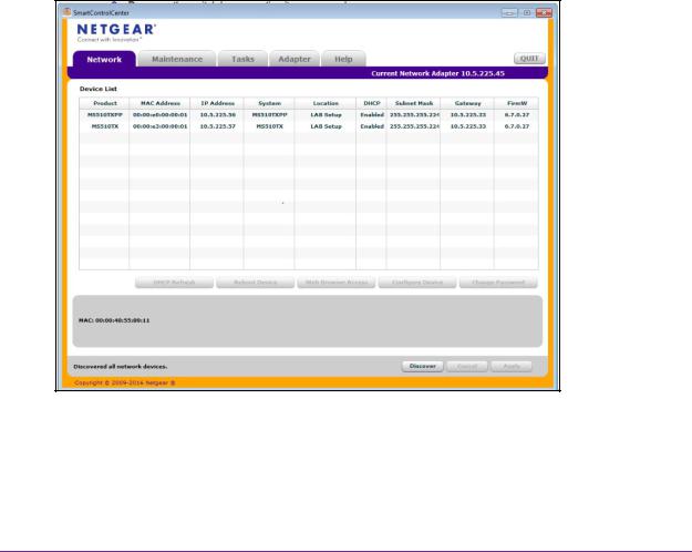
When you connect the switch to your network, the DHCP server automatically assigns an IP address to the switch. Use the Smart Control Center (SCC) to discover the IP address automatically assigned to the switch.
The SCC program runs on a Windows-based computer and is included on the resource CD. You can also download the SCC program from downloadcenter.netgear.com. If you do not use a Windows-based computer, get the IP address of the switch from the DHCP server in the network or use an IP scanner utility, which are available free of charge on the Internet.
Note: The computer that is running the SCC program must be on the same network (that is, in the same broadcast domain) as the switch.
To determine the DHCP-assigned IP address of the switch and access the switch:
1.Connect the switch to a network that includes a DHCP server.
2.Power on the switch by connecting its power cord.
3.Install the Smart Control Center on your computer.
4.Start the Smart Control Center.
5.Click the Discover button.
The Smart Control Center finds your switch.
Get Started
13

Smart Managed Pro Switches MS510TX and MS510TXPP
6.Write down the displayed IP address assigned by the DHCP server.
You need this address later to access the switch directly from a web browser (without using the Smart Control Center).
7.Select the switch by clicking the row for the switch.
8.Click the Web Browser Access button.
The Smart Control Center launches a browser. The login window opens.
9.Enter the switch’s password in the Password field. The default password is password.
The Switch Information page displays. You can now configure the switch.
Get Started
14
Smart Managed Pro Switches MS510TX and MS510TXPP
Access the Switch On-Network Without a DHCP Server
You can use the Smart Control Center (SCC) to set up your switch in a network without a DHCP server and assign a static IP address to the switch.
If you prefer, you can assign the switch a static IP address even if your network does include a DHCP server.
The SCC program runs on a Windows-based computer and is included on the resource CD. You can also download the SCC program from downloadcenter.netgear.com. If you do not use a Windows-based computer, see Access the Switch Off-Network on page 16.
To assign a static IP address to the switch on-network and access the switch:
1.Connect the switch to a network.
2.Power on the switch by connecting its power cord.
3.Install the Smart Control Center on your computer.
4.Start the Smart Control Center.
5.Click the Discover button.
The Smart Control Center finds your switch.
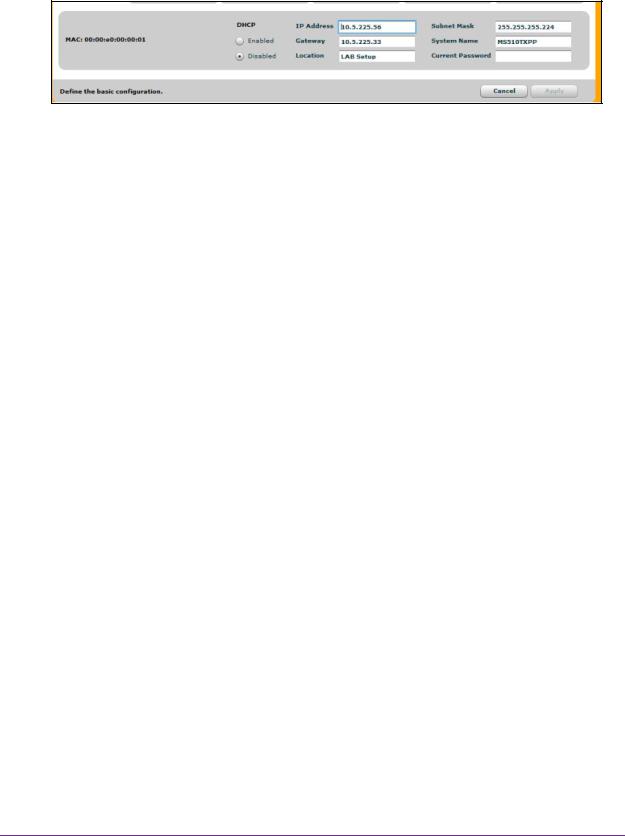
6.Select the switch, and then click the Configure Device button. The page expands to display additional fields at the bottom.
7.Select the Disabled radio button. The DHCP client is disabled.
Get Started
15
Smart Managed Pro Switches MS510TX and MS510TXPP
8.Enter the static switch IP address, gateway IP address, and subnet mask for the switch.
9.Enter the switch password to continue with the configuration change.
The default password is password. You must enter the password each time that you use the Smart Control Center to update the switch settings.
Note: If you change the default password to a custom password (which we recommend) using the local browser interface and need to use the Smart Control Center again, you must enter the custom password for configuration changes to be accepted.
10.Click the Apply button. Your settings are saved.
11.Click the Discover button.
The Smart Control Center finds your switch with its new IP address.
12.Select the switch by clicking the row for the switch.
13.Click the Web Browser Access button.
The Smart Control Center launches a browser. The login window opens.
14.Enter the switch’s password in the Password field. The default password is password.
The Switch Information page displays. You can now configure the switch.
Access the Switch Off-Network
You can connect to the switch directly from a computer and change the settings by using the local browser interface of the switch. The default IP address of the switch is 192.168.0.239. The IP address of the computer that you use to access the switch must in the same subnet as the default IP address of the switch, that is, it must be in the in the 192.168.0.0/24 subnet.
To assign a static IP address to the switch off-network from a directly-connected computer:
1.Record your computer’s TCP/IP configuration settings, and then configure the computer with a static IP address.
Get Started
16

Smart Managed Pro Switches MS510TX and MS510TXPP
For example, configure 192.168.0.210 as the IP address and 255.255.255.0 as the subnet mask.
Note: If you are unsure how to do this, visit netgear.com/search-support.aspx and search for the following:
How to set a static IP address in Windows or
Setting a static IP address on your network adapter in Mac OS
2.Plug the switch into a power outlet and then connect your computer to the switch using an Ethernet cable.
You can connect the Ethernet cable to any Ethernet port on the switch.
3.Open a web browser, and enter http://192.168.0.239. This is the default address of the switch.
The login window opens.
4.Enter the switch’s password in the Password field. The default password is password.
The Switch Information page displays. You can now configure the switch.
5.After you complete the configuration of the switch, reconfigure the computer that you used for this process to its original TCP/IP settings.
You can now connect your switch to your network using an Ethernet cable.
Register the Switch
To qualify for product updates and product warranty, we encourage you to register your product. The first time you log in to the switch, you are given the option of registering with NETGEAR. Registration confirms that your email alerts work, lowers technical support resolution time, and ensures that your shipping address accuracy. We would also like to incorporate your feedback into future product development. We never sell or rent your email address and you can opt out of communications at any time.
When you log in to the switch, you are prompted to register with NETGEAR. However, at any time you can visit the NETGEAR website for registration at https://my.netgear.com/register/register.aspx.
How to Configure Interface Settings
For some features that allow you to configure interface settings, you can apply the same settings simultaneously to any of the following:
•A single port
•Multiple ports
Get Started
17

Smart Managed Pro Switches MS510TX and MS510TXPP
•All ports
•A single LAG
•Multiple LAGs
•All LAGs
•Multiple ports and LAGs
•All ports and LAGs
Many of the pages that allow you to configure or view interface settings include links to display all ports, all LAGs, or all ports and LAGs on the page.
Use these links as follows:
•To display all ports, click the PORTS link.
•To display all LAGs, click the LAGS link.
•To display all ports and LAGs, click the All link.
The procedures in this section describe how to select the ports and LAGs to configure. The procedures assume that you are already logged in to the switch. If you do not know how to log in to the switch, see Access the Switch on page 12.
To configure a single port or LAG:
1.Click the All link to display the all ports and LAGs.
2.Do one of the following:
a.In the Go To Interface field, type the port number and click the Go button.
For example, type g4 for a port or type LAG2 for a LAG. For more information, see
Interface Naming Conventions on page 12.
The check box for the interface is selected, the row for the selected interface is highlighted, and the interface number displays in the heading row.
b.Select the check box for the port or LAG.
The row for the selected interface is highlighted, and the interface number displays in the heading row.
3.Configure the desired settings.
4.Click the Apply button. Your settings are saved.
To configure multiple ports and LAGs:
1.Click the All link to display all ports and LAGs.
2.Select the check box next to each port and LAG to configure. The row for each selected interface is highlighted.
Get Started
18
Smart Managed Pro Switches MS510TX and MS510TXPP
3.Configure the desired settings.
4.Click the Apply button. Your settings are saved.
To configure all ports and LAGs:
1.Click the All link to display all ports and LAGs.
2.Select the check box in the heading row.
The check boxes for all ports and LAGs are selected and the rows for all ports and LAGs are highlighted.
3.Configure the desired settings.
4.Click the Apply button. Your settings are saved.
Local Browser Interface Device View
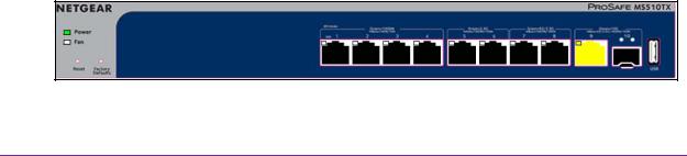
The Device View displays the ports in the local browser interface displays the ports on the switch. This graphic provides an alternate way to navigate to configuration and monitoring options. The graphic also provides information about device ports, current configuration and status, tables, and feature components.
To use the Device View:
1.Connect your computer to the same network as the switch.
You can use a WiFi or wired connection to connect your computer to the network, or connect directly to a switch that is off-network using an Ethernet cable.
2.Launch a web browser.
3.In the address field of your web browser, enter the IP address of the switch.
If you do not know the IP address of the switch, see Access the Switch on page 12. The login window opens.
4.Enter the switch’s password in the Password field. The default password is password.
The Switch Information page displays.
5.Select System > Device View.
The previous figure shows the Device View page for model MS510TX.
Get Started
19

Smart Managed Pro Switches MS510TX and MS510TXPP
The system LEDs are located on the left side.
Depending upon the status of the port, the port color in Device View is either yellow, green, or black (that is, off).
The following table describes the LEDs on the Device View page.
Table 3. LEDs on the Device View page
LED |
Description |
|
|
Power LED |
The Power LED is a bicolor LED that serves as an indicator of power and |
|
diagnostic status: |
|
• Solid green. Power is supplied to the switch and the switch is |
|
operating normally. |
|
• Solid yellow. The switch is in the boot-up stage. |
|
• Off. No power is supplied to the switch. |
|
|
Fan LED |
The Fan LED indicates the following status: |
|
• Off. Fan is operating normally. |
|
• Solid yellow. A problem occurred with the fan. |
|
|
PoE MAX LED |
The PoE MAX Power LED indicates the following PoE conditions at |
(Model MS510TXPP only) |
switch (not port) level: |
|
• Off. More than 7W of PoE power is available for another powered |
|
device (PD). |
|
• Solid yellow. Less than 7W of PoE power is available for another |
|
PD. |
|
• Blinking yellow. The PoE Max LED was activate in the previous two |
|
minutes. |
|
|
1G Ports 1–4, Left LEDs |
The left LEDs for ports 1–4 (g1 to g4) indicate the following status: |
Link, speed, and activity |
• Off. No link is established. |
|
• Solid green. A valid 1 Gbps link is established. |
|
• Blinking green. The port is transmitting or receiving packets at |
|
1 Gbps. |
|
• Solid yellow. A valid 10 Mbps or 100 Mbps link is established. |
|
• Blinking yellow.The port is transmitting or receiving packets at 10 |
|
Mbps or 100 Mbps. |
|
|
1G Ports 1–4, Right LEDs |
The right LEDs for ports 1–4 (g1 to g4) indicate the following status: |
PoE status |
• Off. The port is not delivering PoE. |
(Model MS510TXPP only) |
• Solid green. The port is delivering PoE. |
|
|
|
• Solid yellow. A PoE fault occurred. |
|
|
2.5G Ports 5 and 6, Left LEDs |
The left LEDs for ports 5 and 6 (mg5 and mg6) indicate the following |
Link, speed, and activity |
status: |
|
• Off. No link is established. |
|
• Solid green. A valid 2.5 Gbps link is established. |
|
• Blinking green. The port is transmitting or receiving packets at 2.5 |
|
Gbps. |
|
• Solid yellow. A valid 100 Mbps or 1000 Mbps link is established. |
|
• Blinking yellow. The port is transmitting or receiving packets at 100 |
|
Mbps or 1000 Mbps. |
|
|
Get Started
20
Smart Managed Pro Switches MS510TX and MS510TXPP
Table 3. LEDs on the Device View page (continued)
LED |
Description |
|
|
2.5G Ports 5 and 6, Right LEDs |
The right LEDs for ports 5 and 6 (mg5 and mg6) indicate the following |
PoE status |
status: |
(Model MS510TXPP only) |
• Off. The port is not delivering PoE. |
|
• Solid green. The port is delivering PoE. |
|
• Solid yellow. A PoE fault occurred. |
5G Ports 7 and 8, Left LEDs |
The left LEDs for ports 7 and 8 (mg7 and mg8) indicate the following |
Link, speed, and activity |
status: |
|
• Off. No link is established. |
|
• Solid green. A valid 2.5 Gbps or 5 Gbps link is established. |
|
• Blinking green. The port is transmitting or receiving packets at 2.5 |
|
Gbps or 5 Gbps. |
|
• Solid yellow. A valid 100 Mbps or 1000 Mbps link is established. |
|
• Blinking yellow. The port is transmitting or receiving packets at 100 |
|
Mbps or 1000 Mbps. |
|
|
5G Ports 7 and 8, Right LEDs |
The right LEDs for ports 7 and 8 (mg7 and mg8) indicate the following |
PoE status |
status: |
(Model MS510TXPP only) |
• Off. The port is not delivering PoE. |
|
• Solid green. The port is delivering PoE. |
|
• Solid yellow. A PoE fault occurred. |
|
|
10G Port 9, LED |
The LED for port 9 (xmg9) indicates the following status: |
Link, speed, and activity |
• Off. No link is established. |
|
• Solid green. A valid 10 Gbps link is established. |
|
• Blinking green. The port is transmitting or receiving packets at |
|
10 Gbps. |
|
• Solid yellow. A valid 5 Gbps, 2.5 Gbps, 1000 Mbps, or 100 Mbps |
|
link is established. |
|
• Blinking yellow. The port is transmitting or receiving packets at |
|
5 Gbps, 2.5 Gbps, 1000 Mbps, or 100 Mbps |
SFP+ Port 10, LEDs |
The LEDs for port 10 (xg10, the SFP+ port) indicate the following status: |
Link, speed, and activity |
• Off. No SFP+ module link is established on the fiber port. |
|
• Left LED solid green. The fiber port established a valid 10 Gbps |
|
link. |
|
• Left LED blinking green. The fiber port is transmitting or receiving |
|
packets at 10 Gbps. |
|
• Right LED solid yellow. The fiber port established a valid 1 Gbps |
|
link. |
|
• Right LED blinking yellow. The fiber port is transmitting or receiving |
|
packets at 1 Gbps |
6. To see a menu that displays statistics and configuration options, right-click a port.
Get Started
21
Smart Managed Pro Switches MS510TX and MS510TXPP
The previous figure shows the Device View page for model MS510TXPP.
7.To display the main menu that contains the same options as the navigation menu at the top of the page, right-click the graphic without clicking a specific port.
The previous figure shows the Device View page for model MS510TXPP.
Get Started
22

2. Configure System Information |
2 |
|
|
||
|
|
|
This chapter covers the following topics:
•View and Configure the Switch Management Settings
•Use the Device View
•Configure Power over Ethernet
•Configure SNMP
•Configure LLDP
•Configure DHCP Snooping
•Set Up PoE Timer Schedules
23

Smart Managed Pro Switches MS510TX and MS510TXPP
View and Configure the Switch Management Settings
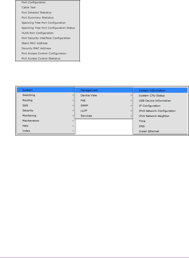
This section describes how to display the switch status and specify some basic switch information, such as the management interface IP address, system clock settings, and DNS information. From the System > Management menu, you can access pages that are described in the following sections:
•View or Define System Information and View Software Versions on page 24
•View the System CPU Status on page 26
•View USB Device Information on page 27
•Configure the IPv4 Address for the Network Interface and Management VLAN on page 28
•Configure the IPv6 Address for the Network Interface on page 30
•View the IPv6 Network Neighbor on page 31
•Configure the Time Settings on page 32
•Configure DNS Settings on page 41
•Configure Green Ethernet Settings on page 45
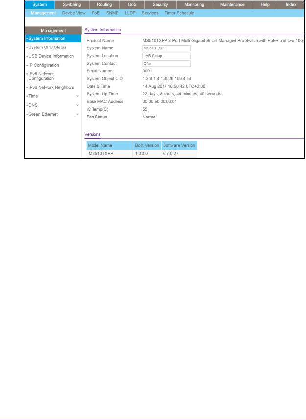
View or Define System Information and View Software Versions
When you log in, the System Information page displays. Use this page to configure and view general device information such as system name, location, and contact, general system temperature, temperatures of the fans, and boot and software versions.
To view or define system information and view software versions:
1.Connect your computer to the same network as the switch.
You can use a WiFi or wired connection to connect your computer to the network, or connect directly to a switch that is off-network using an Ethernet cable.
2.Launch a web browser.
3.In the address field of your web browser, enter the IP address of the switch.
If you do not know the IP address of the switch, see Access the Switch on page 12. The login window opens.
4.Enter the switch’s password in the Password field. The default password is password.
The System Information page displays.
Configure System Information
24
Smart Managed Pro Switches MS510TX and MS510TXPP
5.Define the following fields:
•System Name. Enter the name to identify this switch. You can use up to 255 alphanumeric characters. The default is blank.
•System Location. Enter the location of this switch. You can use up to 255 alphanumeric characters. The default is blank.
•System Contact. Enter the contact person for this switch. You can use up to 255 alphanumeric characters. The default is blank.
6.Click the Apply button. Your settings are saved.
The following table describes the status information that the System Information page displays.
Field |
Description |
Serial Number |
The serial number of the switch. |
|
|
System Object ID |
The base object ID for the switch’s enterprise MIB. |
|
|
Date & Time |
The current date and time. |
|
|
System Up Time |
The number of days, hours, minutes, and seconds since the last system |
|
restart. |
|
|
Base MAC Address |
Universally assigned network address. |
|
|
IC Temp(C) |
Integrated circuit temperature in Celsius values. |
|
|
Fan Status |
The status of fan operations. |
|
|
Model Name |
The model name of the switch. |
|
|
Configure System Information
25

Smart Managed Pro Switches MS510TX and MS510TXPP
Field |
Description |
Boot Version |
The boot code version of the switch. |
|
|
Software Version |
The software version of the switch. |
|
|
View the System CPU Status
Use the System CPU Status page to monitor the CPU, memory resources, and utilization patterns across various intervals to assess the performance of the switch.
To configure and view the system CPU status and utilization:
1.Connect your computer to the same network as the switch.
You can use a WiFi or wired connection to connect your computer to the network, or connect directly to a switch that is off-network using an Ethernet cable.
2.Launch a web browser.
3.In the address field of your web browser, enter the IP address of the switch.
If you do not know the IP address of the switch, see Access the Switch on page 12. The login window opens.
4.Enter the switch’s password in the Password field. The default password is password.
The System Information page displays.
5.Select System > Management > System CPU Status. The CPU Memory Status page displays.
The page shows the total system memory and the available memory in MB.
6.Enable the switch to calculate the CPU utilization:
•CPU Utilization. Select the Disable or Enable radio button. By default, the Enable radio button is selected.
•Refresh Rate. Select a radio button number to specify the number of seconds at which the CPU utilization is computed. By default, the No radio button is selected.
The CPU Input Rate field shows the number of frames forwarded to the CPU per second.
The CPU utilization rate is displayed in a graph. The Y axis represents the CPU utilization in percentage. The X axis represents the number of elapsed seconds and is correlated to the selected refresh rate.
Configure System Information
26

Smart Managed Pro Switches MS510TX and MS510TXPP
View USB Device Information
Use the USB Device Information page to display the USB device status, memory statistics, and directory details.
The limitations for the USB device supported on the switch are as follows:
•The USB disk must comply with the USB 2.0 standard.
•The USB disk must be file type FAT32. File type NTFS is not supported.
To display the USB device information:
1. Connect your computer to the same network as the switch.
You can use a WiFi or wired connection to connect your computer to the network, or connect directly to a switch that is off-network using an Ethernet cable.
2.Launch a web browser.
3.In the address field of your web browser, enter the IP address of the switch.
If you do not know the IP address of the switch, see Access the Switch on page 12. The login window opens.
4.Enter the switch’s password in the Password field. The default password is password.
The System Information page displays.
5.Select System > Management > USB Device Information. The USB Memory Statistics page displays.
6.To refresh the page, click the Refresh button.
The following table describes the USB Memory Statistics information.
Table 4. USB Memory Statistics information
Field |
Description |
|
|
Total Size |
The USB flash device storage size in bytes. |
|
|
Bytes Used |
The size of memory used on the USB flash device. |
|
|
Bytes Free |
The size of memory free on the USB flash device. |
|
|
Configure System Information
27

Smart Managed Pro Switches MS510TX and MS510TXPP
The following table describes the USB Directory Details information.
Table 5. USB Directory Details information
Field |
Description |
|
|
File Name |
The name of the file stored in the USB flash drive. |
|
|
Type |
The type of file, which can be one of the following: |
|
• Folder. A subfolder within the file. |
|
Click the folder name to view the contents of the subfolder. |
|
• File. A file. |
|
• Other. A path, which can be one of the following: |
|
- Current path. The full path for the folder that is being displayed. |
|
- Parent folder path. The path for the parent folder of the folder |
|
that is being displayed. You can click the entry and open the |
|
parent folder. |
|
|
File Size |
The size, in bytes, of the file stored in the USB flash drive. |
|
|
Modification Time |
The last modification time of the file stored in the USB flash drive. |
|
|
Configure the IPv4 Address for the Network Interface and Management VLAN
You can configure network information for the network interface, which is the logical interface used for in-band connectivity with the switch through any of the switch’s ports. You also use the IPv4 address of the network interface to connect to the switch through the local browser interface. The configuration parameters that is associated with the switch’s network interface do not affect the configuration of the ports through which traffic is switched.
To configure the IPv4 address for the network interface and the management VLAN:
1.Connect your computer to the same network as the switch.
You can use a WiFi or wired connection to connect your computer to the network, or connect directly to a switch that is off-network using an Ethernet cable.
2.Launch a web browser.
3.In the address field of your web browser, enter the IP address of the switch.
If you do not know the IP address of the switch, see Access the Switch on page 12. The login window opens.
4.Enter the switch’s password in the Password field. The default password is password.
The System Information page displays.
5.Select System > Management > IP Configuration. The IP Configuration page displays.
Configure System Information
28

Smart Managed Pro Switches MS510TX and MS510TXPP
6.Select a radio button to determine how to configure the network information for the switch management interface:
•Static IP Address. Specifies that the IP address, subnet mask, and default gateway must be manually configured. Enter this information in the fields below this radio button.
•Dynamic IP Address (DHCP). Specifies that the switch must obtain the IP address through a DHCP server.
7.If you select the Static IP Address radio button, configure the following network information:
•IP Address. The IP address of the network interface. Each part of the IP address must start with a number other than zero. For example, IP addresses 001.100.192.6 and 192.001.10.3 are not valid. The factory default IP address is 192.168.0.239.
•Subnet Mask. The IP subnet mask for the interface. The factory default subnet mask is 255.255.255.0.
•Default Gateway. The default gateway for the IP interface. The factory default gateway address is 192.168.0.254.
8.From the Management VLAN ID menu, select the VLAN ID for the management VLAN.
The management VLAN is used to establish an IP connection to the switch from a computer that is connected to a port in the same VLAN. If not specified, the active management VLAN ID is 1 (default), which allows an IP connection to be established through any port.
When the management VLAN is set to a different value, an IP connection can be made only through a port that is part of the management VLAN. Also, the port VLAN ID (PVID) of the port to be connected in that management VLAN must be the same as the management VLAN ID.
Note: Make sure that the VLAN that must be the management VLAN exists. Also make sure that the PVID of at least one port in the VLAN is the same as the management VLAN ID. For information about creating VLANs and configuring the PVID for a port, see Configure VLANs on page 94.
The following requirements apply to the management VLAN:
•Only one management VLAN can be active at a time.
•When a new management VLAN is configured, connectivity through the existing management VLAN is lost.
•The management station must be reconnected to the port in the new management VLAN.
9.Click the Apply button. Your settings are saved.
Configure System Information
29

Smart Managed Pro Switches MS510TX and MS510TXPP
Configure the IPv6 Address for the Network Interface
You can configure the IPv6 address for the network interface, which is the logical interface used for in-band connectivity with the switch through any of the switch’s front-panel ports. You also use the IPv6 address of the network interface to connect to the switch through the local browser interface. The configuration parameters that is associated with the switch’s network interface do not affect the configuration of the ports through which traffic is switched.
To access the switch over an IPv6 network, you must initially configure the switch with IPv6 information (IPv6 prefix, prefix length, and default gateway). IPv6 can be configured using any of the following options:
•IPv6 autoconfiguration
•DHCPv6
When in-band connectivity is established, IPv6 information can be changed using SNMP-based management or web-based management.
To configure the IPv6 address for the network interface:
1.Connect your computer to the same network as the switch.
You can use a WiFi or wired connection to connect your computer to the network, or connect directly to a switch that is off-network using an Ethernet cable.
2.Launch a web browser.
3.In the address field of your web browser, enter the IP address of the switch.
If you do not know the IP address of the switch, see Access the Switch on page 12. The login window opens.
4.Enter the switch’s password in the Password field. The default password is password.
The System Information page displays.
5.Select System > Management > IPv6 Network Configuration. The IPv6 Network Global Configuration page displays.
6.Ensure that the Admin Mode Enable radio button is selected.
7.Select IPv6 Address Auto Configuration Mode Enable radio button to enable the network interface to acquire an IPv6 address through IPv6 Neighbor Discovery Protocol (NDP) and through the use of router advertisement messages.
When this mode is disabled, the network interface does not use the native IPv6 address autoconfiguration features to acquire an IPv6 address.
8.In the Current Network Configuration Protocol field define the IPv6 network interface to receive an IPv6 address from a DHCP server. The default value is None.
9.If the above field is set to DHCPv6 Protocol, the DHCPv6 Client DUID field (read only) displays the DHCPv6 client DUID
Configure System Information
30
 Loading...