


GS728TS, GS728TPS,
GS752TS, and GS752TPS
Smart Switch
Hardware Installation Guide
350 East Plumeria Drive
San Jose, CA 95134
USA
January 2012 202-10994-01 v1.0

GS728TS, GS728TPS, GS752TS, and GS752TPS Smart Switch Hardware Installation Guide
©2012 NETGEAR, Inc. All rights reserved
No part of this publication may be reproduced, transmitted, transcribed, stored in a retrieval system, or translated into any language in any form or by any means without the written permission of NETGEAR, Inc.
Technical Support
Thank you for choosing NETGEAR. To register your product, get the latest product updates, get support online, or for more information about the topics covered in this manual, visit the Support website at http://support.netgear.com.
Phone (US & Canada only): 1-888-NETGEAR
Phone (Other Countries): Check the list of phone numbers at
http://support.netgear.com/app/answers/detail/a_id/984
Trademarks
NETGEAR, the NETGEAR logo, ReadyNAS, ProSafe, ProSecure, Smart Wizard, Auto Uplink, X-RAID2, and NeoTV are trademarks or registered trademarks of NETGEAR, Inc. Microsoft, Windows, Windows NT, and Vista are registered trademarks of Microsoft Corporation. Other brand and product names are registered trademarks or trademarks of their respective holders.
Statement of Conditions
To improve internal design, operational function, and/or reliability, NETGEAR reserves the right to make changes to the products described in this document without notice. NETGEAR does not assume any liability that may occur due to the use, or application of, the product(s) or circuit layout(s) described herein.
Revision History
Publication Part Number |
Version |
Publish Date |
Comments |
|
|
|
|
202-10994-01 |
v1.0 |
January 2012 |
First publication |
|
|
|
|
2 |

Table of Contents
Chapter 1 Introduction
Overview . . . . . . . . . . . . . . . . . . . . . . . . . . . . . . . . . . . . . . . . . . . . . . . . . . . 7
Features . . . . . . . . . . . . . . . . . . . . . . . . . . . . . . . . . . . . . . . . . . . . . . . . . . . 7
Stacking . . . . . . . . . . . . . . . . . . . . . . . . . . . . . . . . . . . . . . . . . . . . . . . . . . 9
Package Contents . . . . . . . . . . . . . . . . . . . . . . . . . . . . . . . . . . . . . . . . . . . 10
Chapter 2 Physical Description
GS728TS Front-Panel and Back-Panel Configuration . . . . . . . . . . . . . . . 12
GS728TPS Front-Panel and Back-Panel Configuration . . . . . . . . . . . . . . 13
GS752TS Front-Panel and Back-Panel Configuration . . . . . . . . . . . . . . . 15
GS752TPS Front-Panel and Back-Panel Configuration . . . . . . . . . . . . . . 16
LED Designations . . . . . . . . . . . . . . . . . . . . . . . . . . . . . . . . . . . . . . . . . . . 17
RJ-45 Port LEDs . . . . . . . . . . . . . . . . . . . . . . . . . . . . . . . . . . . . . . . . . . 17
SFP Port LEDs . . . . . . . . . . . . . . . . . . . . . . . . . . . . . . . . . . . . . . . . . . . 18
System LEDs . . . . . . . . . . . . . . . . . . . . . . . . . . . . . . . . . . . . . . . . . . . . . 18
Device Hardware Interfaces . . . . . . . . . . . . . . . . . . . . . . . . . . . . . . . . . . . 19
RJ-45 Ports . . . . . . . . . . . . . . . . . . . . . . . . . . . . . . . . . . . . . . . . . . . . . . 19
SFP Ports . . . . . . . . . . . . . . . . . . . . . . . . . . . . . . . . . . . . . . . . . . . . . . . 19
Reset Button . . . . . . . . . . . . . . . . . . . . . . . . . . . . . . . . . . . . . . . . . . . . . 20
Factory Defaults Button . . . . . . . . . . . . . . . . . . . . . . . . . . . . . . . . . . . . . 20
Select Button . . . . . . . . . . . . . . . . . . . . . . . . . . . . . . . . . . . . . . . . . . . . . 20
Chapter 3 Applications
Desktop Switching . . . . . . . . . . . . . . . . . . . . . . . . . . . . . . . . . . . . . . . . . . . 22
Backbone Switching . . . . . . . . . . . . . . . . . . . . . . . . . . . . . . . . . . . . . . . . . 23
Chapter 4 Installation
Step 1: Preparing the Site . . . . . . . . . . . . . . . . . . . . . . . . . . . . . . . . . . . . . 25 Step 2: Installing the Switch . . . . . . . . . . . . . . . . . . . . . . . . . . . . . . . . . . . 25 Installing the Switch on a Flat Surface. . . . . . . . . . . . . . . . . . . . . . . . . . 25 Installing the Switch in a Rack . . . . . . . . . . . . . . . . . . . . . . . . . . . . . . . . 25 Step 3: Checking the Installation . . . . . . . . . . . . . . . . . . . . . . . . . . . . . . . . 26 Step 4: Connecting Devices to the Switch. . . . . . . . . . . . . . . . . . . . . . . . . 26 Step 5: Installing an SFP Transceiver Module . . . . . . . . . . . . . . . . . . . . . 27 Step 6: Installing Device as Stand-alone or Stack Master. . . . . . . . . . . . . 28 Step 7: Applying AC Power . . . . . . . . . . . . . . . . . . . . . . . . . . . . . . . . . . . . 29 Step 8: Managing the Switch using a Web Browser or the PC Utility . . . . 30
Contents | 3

GS728TS, GS728TPS, GS752TS, and GS752TPS Smart Switch Hardware Installation Guide
Appendix A Troubleshooting
Troubleshooting Chart . . . . . . . . . . . . . . . . . . . . . . . . . . . . . . . . . . . . . . . .31
Additional Troubleshooting Suggestions . . . . . . . . . . . . . . . . . . . . . . . . . .32
Network Adapter Cards . . . . . . . . . . . . . . . . . . . . . . . . . . . . . . . . . . . . .32
Configuration . . . . . . . . . . . . . . . . . . . . . . . . . . . . . . . . . . . . . . . . . . . . .32
Switch Integrity . . . . . . . . . . . . . . . . . . . . . . . . . . . . . . . . . . . . . . . . . . . .32
Auto-Negotiation . . . . . . . . . . . . . . . . . . . . . . . . . . . . . . . . . . . . . . . . . . .32
Appendix B Technical Specifications
Appendix C Notification of Compliance
Index
4 | Contents

GS728TS, GS728TPS, GS752TS, and GS752TPS Smart Switch Hardware Installation Guide
Contents | 5

1. Introduction |
1 |
|
|
||
|
|
|
Congratulations on the purchase of your NETGEAR® ProSafeTM GS728TS, GS728TPS, GS752TS, or GS752TPS Smart Switch! Your Smart Switch is a state-of-the-art, high-performance, IEEE-compliant network solution designed for users who require a large number of ports and want the power of Gigabit connectivity to eliminate bottlenecks, boost performance, and increase productivity. There are either 24 (GS728TS and GS728TPS) or 48 (GS752TS and GS752TPS) twisted-pair ports on the front panel of the switch which support nonstop 10/100/1000 networks. The front panel also has six SFP ports, 2 of which are combo ports, 2 are dedicated 1000M ports, and the last 2 ports can be used for 1000M uplink or 2.5 Gbps stacking.
The GS728TS, GS728TPS, GS752TS, and GS752TPS Smart Switch Hardware Installation Guide describes how to install and power on the Smart Switch. The information in this manual is intended for readers with intermediate computer and Internet skills.
This chapter serves as an introduction to the Smart Switch and provides the following information:
•Overview
•Features
•Package Contents
Chapter 1. Introduction | 6

GS728TS, GS728TPS, GS752TS, and GS752TPS Smart Switch Hardware Installation Guide
Overview
The NETGEAR GS728TS, GS728TPS, GS752TS, or GS752TPS Smart Switch provides either 24 (GS728TS and GS728TPS) or 48 (GS752TS and GS752TPS) twisted-pair ports that support nonstop 10/100/1000M networks. The switch also has six built-in Small Form Factor Pluggable (SFP) GBIC slots, 2 of which are combo ports, 2 of which are dedicated 1000M ports, and the last 2 ports can be used for 1000M uplink or 2.5 Gbps stacking.
Using these Gigabit slots, you can create high-speed connections to a server or network backbone. For example, you can:
•Connect switches to each other with high-speed links
•Link to high-speed servers
•Provide 10/100/1000M copper and 100M/1000M fiber connectivity
•Connect up to six switches in a stack to create a high-port-capacity solution with a single point of administration
The NETGEAR GS728TS, GS728TPS, GS752TS, or GS752TPS Smart Switch also provides the benefit of administrative management with a complete package of features for the observation, configuration, and control of the network. With a Web-based Graphical User Interface (GUI), the switch’s many capabilities can be viewed and used in a simple and intuitive manner. The switch’s management features include configuration for port and switch information, VLAN for traffic control, port trunking for increased bandwidth, and Class of Service (CoS) for traffic prioritization. These features provide better understanding and control of the network. Initial discovery of the switch on the network requires the Smart Control Center program, a utility that runs on a PC.
The NETGEAR GS728TS, GS728TPS, GS752TS, or GS752TPS Smart Switch can be free standing, stacked with other switches, or rack mounted in a wiring closet or equipment room. It is IEEE-compliant and offers low latency for high-speed networking. All ports can automatically negotiate to the highest speed. This capability makes the switch ideal for environments that have a mix of Ethernet, Fast Ethernet, or Gigabit Ethernet devices. In addition, all RJ-45 ports operate in half-duplex or full-duplex mode. The maximum segment length is 328 feet (100 meters) over Category 5 Unshielded Twisted-Pair (UTP) cable.
Features
The following list identifies the key features of the Smart Switch:
•Interfaces:
•GS728TS/GS752TS
•24/48 x 10/100/1000 Mbps copper ports.
•2 x Combo ports to support 10/100/1000 Mbps copper ports or 1G/100M optical module.
•2 x SFP (slot) to support 1G optical module.
Chapter 1. Introduction | 7

GS728TS, GS728TPS, GS752TS, and GS752TPS Smart Switch Hardware Installation Guide
•2 x SFP (slot) to support 1G optical module (uplink) or 2.5G stacking (via stacking cable).
•GS728TPS/GS752TPS
•24/48 PoE-capable 10/100/1000 Mbps copper ports (8 PoE+ capable)
•2 x Combo ports to support 10/100/1000 Mbps copper ports or 1G/100M optical module.
•2 x SFP (slot) to support 1G optical module.
•2 x SFP (slot) to support 1G optical module (uplink) or 2.5G stacking (via stacking cable).
•Stacking ports
•GS728TS/GS728TPS: Port 27 and port 28 can be used as the stacking ports or as uplink ports.
•GS752TS/GS752TPS: Port 51 and port 52 can be used as the stacking ports or as uplink ports.
•Six 100/1000Mbps SFP slots and two 2.5Gbps ports for stacking.
•Full NETGEAR Smart Switch functionality.
•Stack will support up to a maximum of 6 switches.
•Mix and match stacking supported on the GS7xxTS/GS7xxTPS family (GS728TS, GS752TS, GS728TPS and GS752TPS).
•Full compatibility with IEEE standards:
•IEEE 802.3i (10BASE-T)
•IEEE 802.3u (100BASE-TX)
•IEEE 802.3ab (1000BASE-T)
•IEEE 802.3z (1000BASE-x)
•IEEE802.3az (Energy Efficient Ethernet)
•IEEE 802.3x (Full-duplex flow control)
•IEEE802.3af (DTE Power via MDI)
•IEEE802.3at (DTE Power via MDI Enhancements)
•PoE
•GS728TPS: Port 1-8 support both IEEE802.3 at and af, and port 9-24 support IEEE802.3af.
•GS752TPS: Port 1-8 support both IEEE802.3 at and af, and port 9-48 support IEEE802.3af.
•Autosensing and auto-negotiating capabilities for all ports.
•Auto Uplink™ on all ports to make the right connection.
•Automatic address learning function to build the packet-forwarding information table. The table contains up to 16K Media Access Control (MAC) addresses.
•GS7xxTS Model LEDs: Port LED, Power and Status LED, FAN status LED and Master LED.
8 | Chapter 1. Introduction

GS728TS, GS728TPS, GS752TS, and GS752TPS Smart Switch Hardware Installation Guide
•GS7xxTPS model LEDs: Power and Status LED, FAN status LED, Master LED, LED mode LED and Max PoE LED.
•Stack ID LED to display stack member ID (1-6).
•Store-and-Forward transmission to remove bad packets from the network.
•Full-duplex IEEE 802.3x pause frame flow control.
•Active flow control to minimize packet loss and frame drops.
•Half-duplex backpressure control.
•Per port LEDs and power LED.
•Internal open frame power supply.
•Standard NETGEAR 7xx series chassis.
•NETGEAR Green product series power-saving features:
•Automatic power consumption adjustment based on the RJ-45 cable length.
•Per port automatic power down when the port link is down.
•IEEE802.3az, EEE (Energy Efficient Ethernet) compliance.
Stacking
A stack can be controlled and managed from a single unit called the master unit. Any other unit member of the stack is named stack slave member.
In particular, firmware can be downloaded from the stack master to the other units in the stack.
A unit serving as Stack Master runs the fully operational software of a switch. In addition, it runs the master part of the Distributed Switching Application that configures and manages all other units in the stack. Generally, the master operates the remote Slave’s low-level drivers, through the Distributed Switching application part that is running in the context of the Slave.
During the Stacking setup, the switches will auto-select one as the Stacking Master. All other devices are named as slave stack members, and assigned a unique Unit ID. One of the slave units is designated as the backup master. The backup master acts as a slave stack master, but can become a stack master in the event of failure of the stack master. In the default configuration, the master and backup master are assigned unit IDs of 1 and 2, respectively. The administrator can use the Web interface to configure different ID assignments. The Stack Master provides a Single point of control and management as well as a single interface in which to control and manage the stack.
Switch software is downloaded separately for each stack member. However, all units in the stack must be running the same software version.
A stack unit can operate in one of the following Modes:
• Standalone unit runs as a general switch. The standalone unit does not run the stacking application until it is connected to a stack.
Chapter 1. Introduction | 9

GS728TS, GS728TPS, GS752TS, and GS752TPS Smart Switch Hardware Installation Guide
•The Master unit manages the entire stack, and is responsible for the entire stack configuration. All protocols run in the context of the Master unit. It updates and synchronizes the Backup master.
•A master-backup unit runs as a slave unit as described above, and in addition, it continuously monitors the existence and operation of the stack master. If the master unit fails, the master-backup unit will assume the stack-master role. (“Switchover”).
•A slave unit only runs a slave version of the Distributed Switching Algorithm, which allows the applications running on the Master unit’s CPU to control and manage the resources of the slave unit.
Package Contents
Figure 1 shows the package contents of the GS728TS, GS728TPS, GS752TS, or GS752TPS Smart Switch (the GS752TS is shown in this example).
Rubber |
AC |
power |
|
footpads |
cord |
Rack |
|
mount kit |
|
Smart Switch
Resource CD
Installation Guide
Figure 1. Package Contents (GS752TS Shown)
Verify that the package contains the following:
•GS728TS, GS728TPS, GS752TS, or GS752TPS Smart Switch
•Rubber footpads for tabletop installation
•Rackmounting kits
•Power cord
•Installation guide
10 | Chapter 1. Introduction
GS728TS, GS728TPS, GS752TS, and GS752TPS Smart Switch Hardware Installation Guide
• Smart Switch Resource CD with NETGEAR Smart Control Center and User’s Manual
If any item is missing or damaged, contact the place of purchase immediately.
Chapter 1. Introduction | 11
2. Physical Description |
2 |
|
|
||
|
|
|
This chapter describes the GS728TS, GS728TPS, GS752TS, and GS752TPS Smart Switch hardware features. Topics include:
•GS728TS Front-Panel and Back-Panel Configuration
•GS728TPS Front-Panel and Back-Panel Configuration
•GS752TS Front-Panel and Back-Panel Configuration
•GS752TPS Front-Panel and Back-Panel Configuration
•LED Designations
•Device Hardware Interfaces
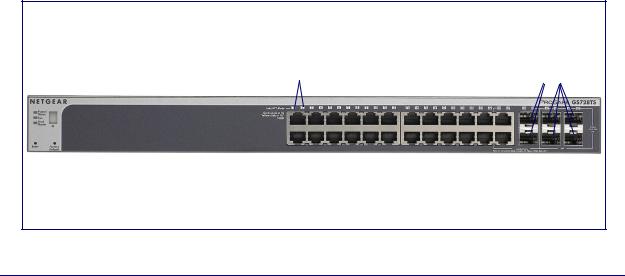
GS728TS Front-Panel and Back-Panel Configuration
The GS728TS Smart Switch has 24 10/100/1000 Mbps copper ports and 6 SFP fiber ports, 2 of which are combo ports. Up to two SFP ports (port 27 and 28) at a time can be used as stacking ports.
Each port is capable of sensing the line speed and negotiating the duplex mode with the link partner automatically.
Figure 2 illustrates the front panel of the NETGEAR GS728TS Smart Switch.
Power, Fan, and |
|
|
|||
Stack Master LEDs |
Link/Speed/ACT LEDs |
Combo and Dedicated |
|||
|
|
|
Stack ID LED |
SFP Ports |
|
|
|
|
|
||
|
|
|
|
|
|
|
|
|
|
|
|
|
|
|
|
|
|
|
|
|
|
|
|
|
|
|
|
|
|
|
Factory |
|
|
||
10/100/1000M Ethernet Ports |
|||||
|
Defaults Button |
||||
|
|
|
|||
|
|
|
|
|
|
Reset Button |
|
|
|||
Figure 2. GS728TS Front Panel
Chapter 2. Physical Description | 12
GS728TS, GS728TPS, GS752TS, and GS752TPS Smart Switch Hardware Installation Guide
The front panel contains the following:
•24 RJ-45 connectors for 10/100/1000 Mbps autosensing Gigabit Ethernet switching ports.
•2 combo ports (port 23 and 24) to support 10/100/1000 Mbps copper or 100M/1G optical module.
•2 dedicated SFP ports (port 25 and 26) to support 1G optical module.
•2 dedicated SFP ports (port 27 and 28) to support 1G optical module (uplink) or 2.5G stacking (via stacking cable).
•Up to two of these ports (ports 27 and 28) can alternatively be used as stacking ports
•Reset button to restart the device.
•Recessed default reset button to restore the device back to the factory defaults.
•Link, Speed, and Activity LEDs for each port.
•Power, Fan Status, Stack Master, and Stack ID LEDs.
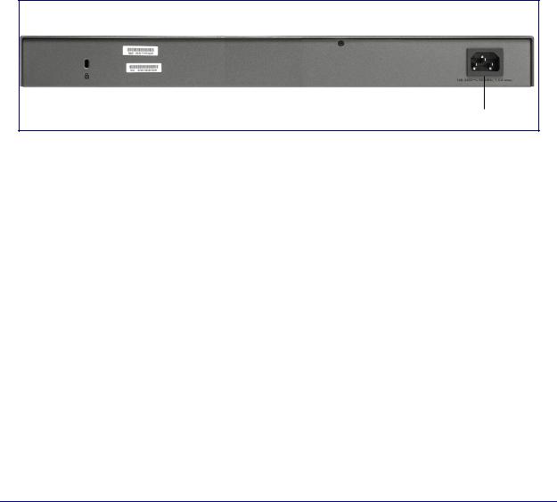
Figure 3 illustrates the NETGEAR GS728TS Smart Switch back panel.
Power Connector
Figure 3. GS728TS Back Panel
The back panel contains a power connector.
GS728TPS Front-Panel and Back-Panel Configuration
The GS728TPS Smart Switch has 24 10/100/1000 Mbps PoE capable copper ports and 6 SFP fiber ports, 2 of which are combo ports. Up to two SFP ports (port 27 and 28) at a time can be used as stacking ports.
Each port is capable of sensing the line speed and negotiating the duplex mode with the link partner automatically.
Figure 4 illustrates the front panel of the NETGEAR GS728TPS Smart Switch.
Chapter 2. Physical Description | 13
 Loading...