


NEC T3415 User Manual

Proprietary Notice and Liability Disclaimer
The information disclosed in this document, including all designs and
related materials, is the valuable property of NEC Computer Systems
Division, Packard Bell NEC, Inc. (hereinafter “NEC CSD”) and/or its
lice nsor s. NEC CSD and/or its licens ors , as ap prop ria te, res erve a ll pat ent,
copyright and other proprietary rights to this document, including all
desi g n, manu fa c t ur in g, r eproduc ti o n, u se, a nd s a l es r ight s th ereto, except to
the extent said r i ghts a re expr essly grant e d to oth ers.
The NEC CSD product(s) discussed in this document are warranted in
accordance with the terms of the Warranty Statement accompanying each
product. However, actual performance of each such product is dependent
upon factors such as system configuration, customer data, and operator
contr ol. Since imp lemen ta tio n by custo mers of each p rodu ct may var y, th e
suitability of specific product configurations and applications must be
determined by the customer and is not warranted by NEC CSD.
To allow for design and specification improvements, the information in this
document is subject to change at any time, without notice. Reproduction
of this document or portions thereof without prior written approval of
NEC CSD is pr ohibite d.
NEC and PowerMate are registered trademarks of NEC Corporation, used under license.
All other product, brand, or trade names used in this publication are the trademarks or
registere d t rademarks of th eir respe ct ive trademark ow ners.
First Printing — August 1999
Copyright 1999
NEC Computer Systems Division
6000 Florin-Perkins Road
Sacramento, CA 95828-1037
All Rights Reserved

Contents
Using This Guide
Text Conventions.............................................................................xi
Related Documents.........................................................................xii
1 Reviewing System Features
Front Features............................................................................... 1-2
System Controls and Lamps .................................................. 1-3
Diskette Drive A.................................................................... 1-4
Universal Serial Bus Port....................................................... 1-4
CD-ROM Drive..................................................................... 1-5
DVD-ROM Drive.................................................................. 1-5
Tape Backup Unit.................................................................. 1-5
Zip Drive............................................................................... 1-6
PC Card Adapter................................................................... 1-6
LS-120 SuperDisk Drive ....................................................... 1-6
Rear Features................................................................................ 1-7
External Connectors.............................................................. 1-8
Power Supply Features.........................................................1-10
Inside Features.............................................................................1-10
System Board .......................................................................1-11
Network Board.....................................................................1-12
Modem Board......................................................................1-12
Storage Device Support........................................................1-12
Chassis ........................................................................................1-12
Speakers......................................................................................1-13
System Features...........................................................................1-13
Hardware..............................................................................1-13
Software...............................................................................1-14
Preloaded Operating System.........................................1-14
NEC OS Restore CD.....................................................1-15
NEC Application and Driver CD...................................1-15
Security........................................................................1-16
Contents iii

2 Setting Up the System
Cable Connections........................................................................ 2-2
Startup.......................................................................................... 2-3
Shutdown...................................................................................... 2-4
Power-Saving Operation............................................................... 2-5
System Care.................................................................................. 2-6
Protecting Your System From Damage.................................. 2-6
Keeping Your System in Good Condition.............................. 2-8
Moving or Shipping Your System.......................................... 2-9
More Information.........................................................................2-10
3 Configuring the System
Configuration Tools and Utilities.................................................. 3-2
BIOS Setup Utility........................................................................ 3-5
How to Start BIOS Setup....................................................... 3-6
How to Use BIOS Setup........................................................ 3-7
Main Menu............................................................................ 3-7
Advanced Menu...................................................................3-11
Security Menu ......................................................................3-18
Exit Menu............................................................................3-19
FLASH Utility.............................................................................3-20
NEC OS Restore CD....................................................................3-21
Introducing OS Restore Options...........................................3-21
Choosing a Restore Program.................................................3-21
Launching the NEC OS Restore CD.....................................3-22
Auto Rebuild and Restore.....................................................3-24
Custom Rebuild and Restore.................................................3-26
Fixing the Operating System.................................................3-29
NEC Application and Driver CD..................................................3-31
Launching the Application and Driver CD ............................3-31
Installing Software...............................................................3-32
NEC Help Center.........................................................................3-33
Installing the NEC Help Center ............................................3-33
Uninstalling the NEC Help Center........................................3-34
Resolutions for NEC VistaScan USB Monitors............................3-34
iv Contents

System Board Jumper Settings.....................................................3-35
Processor Jumper Settings....................................................3-37
Clear CMO S/Pass word.........................................................3-38
Power On Mode...................................................................3-40
4 Installing Options
General Rules............................................................................... 4-2
Safety Precautions......................................................................... 4-3
System Unit Covers...................................................................... 4-4
Removing the Left Side Cover............................................... 4-5
Replacing the Left Side Cover............................................... 4-7
Removing the Right Side Cover............................................. 4-9
Replacing the Right Side Cover............................................4-11
System Board Options..................................................................4-12
Memory Upgrade.................................................................4-13
Checking System Memory............................................4-15
Removing a DIMM.......................................................4-16
Installing a DIMM........................................................4-17
Processor Upgrade................................................................4-19
Removing a Celeron or Pentium III Processor...............4-20
Inst alling a Cel eron or Pentium III Upgrade Process or ..4- 22
Removing the Pentium II Processor...............................4-24
Installing the Pentium II Upgrade Processor..................4-26
Expansion Boards........................................................................4-29
Locating Expansion Slots and Connectors ............................4-30
Installing an Expansion Board..............................................4-31
Removing an Expansion Board.............................................4-33
AGP Board..................................................................................4-33
Removing the AGP Graphics Board.....................................4-33
Installing the AGP Graphics Board.......................................4-34
Data Storage Devices...................................................................4-35
Locating Device Bays...........................................................4-35
Preparing the Device ............................................................4-37
Connecting Device Cables....................................................4-37
Diskette Drive Signal Cable..........................................4-40
IDE Signal Cables.........................................................4-41
System Power Cables....................................................4-41
Contents v

Cabling Storage Devices.......................................................4-41
IDE Drive Cabling........................................................4-42
Diskette Drive Cabling..................................................4-43
PC Card Adapter Cabling..............................................4-43
Network Board Wake-On LAN Cabling........................4-44
Installing Storage Devices....................................................4-45
Removing the Front Panel.............................................4-45
Replacing the Front Panel.............................................4-48
Installing a 3 1/2-Inch Hard Drive.................................4-48
Installing a 5 1/4-Inch Device........................................4-51
5 Solving System Problems
Solutions to Common Problems.................................................... 5-2
System Problems................................................................... 5-2
Diskette Drive Problems........................................................ 5-4
Monitor Problems.................................................................. 5-5
Keyboard/Mouse Problems.................................................... 5-6
CD-ROM Drive Problems..................................................... 5-7
Speaker Problems .................................................................. 5-8
How to Clean the Mouse ............................................................... 5-9
Battery Replacement....................................................................5-11
How to Get Help..........................................................................5-14
Help From Your Company...................................................5-14
Help From Your NEC CSD Dealer.......................................5-14
Help From NEC CSD Technical Support Center...................5-15
NEC CSD Warranty/Non-Warranty Repair Service..............5-16
6 Getting Services and Support
NEC CSD Website........................................................................ 6-2
NEC CSD FTP Site....................................................................... 6-3
Email/Fax Technical Support Service............................................ 6-3
NEC CSD Bulletin Board System................................................. 6-4
NEC CSD Technical Support Services.......................................... 6-7
vi C ont ent s

A Setting Up a Healthy Work Environment
Making Your Computer Work for You..........................................A-2
Arrange Your Equipment.............................................................. A-4
Adjust Your Chair.........................................................................A-5
Adjust Your Input Devices ............................................................A-7
Adjust Your Monitor.....................................................................A-9
Vary Your Workday....................................................................A-11
Pre-existing Conditions and Psychosocial Factors.......................A-12
Checking Your Comfort: How Do You Measure Up?..................A-13
Checking Your Chair...........................................................A-13
Checking Your Keyboard....................................................A-13
Checking Your Mouse.........................................................A-13
Checking Your Monitor.......................................................A-13
Checking You .....................................................................A-14
B System Specifications
System Processor..........................................................................B-2
Processor Support..................................................................B-2
Secondary Cache...................................................................B-3
Processor Socket ...................................................................B-3
Random Access Memory (RAM)..................................................B-3
Cache Memory .............................................................................B-3
Read Only Memory (ROM)..........................................................B-3
Calendar Clock.............................................................................B-4
Input/Output (I/O) Features ...........................................................B-4
Video Memory..............................................................................B-5
Sound System...............................................................................B-6
Fax/Modem Board........................................................................B-6
Peripherals ....................................................................................B-6
Network Board......................................................................B-6
AGP Graphics Board.............................................................B-7
Diskette Drive.......................................................................B-7
Hard Drive............................................................................B-8
Content s vii

CD-ROM Drive.....................................................................B-8
DVD-ROM Drive..................................................................B-8
PC Card Adapter...................................................................B-9
Zip Drive...............................................................................B-9
Tape Backup Unit..................................................................B-9
Speakers..............................................................................B-10
Dimensions .................................................................................B-10
System Unit......................................................................... B-10
Keyboard.............................................................................B-10
Power .........................................................................................B-10
Operating Environment...............................................................B-10
Compliance.................................................................................B-11
Index
viii Contents

Using This Guide
The PowerMate VT 300 Series User’s Guide provides a
comprehensive reference to infor mat ion about your
computer.
The guide contains the following information:
Chapter 1, Reviewing Syste m Featur es, provides a look at
the front, rear, internal, and peripheral features of the
syste m. It also gives a summary of t he system’s hardware ,
software, and secur it y featur es.
The chapter includes a quick-reference chart for finding
information described more fully later in the document.
Chapter 2, Setting Up the System, explains how to set up,
start up, and shut down the syste m. It also provides
information on insta lling applications, and tips on caring
for the system.
Chapter 3, Configuring the System, describes how to use
the software utilities shipped with your system, including
the BIOS Setup Utility, t he NEC OS Rest ore CD, and the
NEC Applicat ion and Driver CD. It also pro vides
info rmation fo r setting s ys tem bo ard jumpers .
Chapter 4, Installing Options, provides detailed
installation procedures for system upgrades and options.
Chap ter 5, Solving System Proble ms , contains
troubleshooting tips fo r solvin g simple pr oblems a nd
describes how to find help when you cannot solve a
problem yourself.
Using This Guide ix

Chapter 6, Getting Services and Support, describes the
services avai lable t o you for info rmation and help, and
describes how to access the services.
Appendix A, Setting Up a Healthy Work Environment,
contains guidelines to help you use your computer
productively and safely. This appendix also instructs you
on how to set up and use your computer to reduce your
risk of developing nerve, muscle, or tendon disorders.
!
WARNING
Prolonged or impr oper use of a c om puter
workstation m ay pose a risk of serious injury. To
reduce your ri sk of i njur y, set up and use your
computer in the manner described in Appendix
A, Setting Up a Healthy Wor k Envir onm ent.
Appendix B, System Specifications, provides a technical
description of your computer and its components.
x Using This Guide

Text Conventions
This guide u ses the following text co nventions.
Warnings, caut ions, and notes have the following
meanings:
!
WARNING
Warnings aler t you to situations that could result
in serious personal i njury or loss of life.
!
CAUTION
Cautions indicate situations that can damage the
hardware or software.
:
Note
the material being described.
Notes give important information about
Names of keyboard keys are printed as they appear on the
keyboard, for example,
Text or keystrokes that you enter appear in boldface type.
For example, type
File names are printed in uppercase letters. For example,
Ctrl, Alt
abc123
and press
, or
Enter
Enter
.
.
AUTOEXEC.BAT.
Using This Guide xi

Related Documents
In addition to this guide, the following printed documentation
ships with your computer.
NEC PowerMate VT 300i Series Quick Setup/Quick
Reference
The Quick Setup shows how to quickly get the system
connected and powered on.
The Quick Reference briefly describes the documentation,
NEC CSD tools and utilities, so ftware applications, and
services availa ble w ith the NEC PowerMate® VT 300
Series computer.
How Does Your Workplace Measure Up?
This brochure provides information for setting up and
using the computer productively and safely. Informat ion
includes guidelines to reduce the risk of injury associated
with using a computer.
NEC PowerMate VT 300 Series Release Notes
Release Not es pro v ide additional information about the
computer that was not available at the time the user’s
guide was printed.
xii Using This Guide

Your system comes with the following online document ation
on the NEC Application and Driver CD.
NEC Help Center
The NEC Help Center is an online guide to Po wer Mate
computers. It provides infor mation about your system
under the following topics: System Tour, System
Information, System Upgrades, Service and Support, and
Reference.
Healthy Environment
This is an online h elp file that complements the “How
Does Your Workplace Measure Up?” broc hur e .
In addition, service and re ference manuals are available on
the Internet at the Service and Support area of the NEC CSD
website (see Chapter 6 for access information).
Using This Guide xiii

Reviewi n g System
Features
Front Features
Rear Features
Inside Features
Speakers
System Features
1
!
Prolonged or impr oper use of a c om puter
workstation m ay pose a risk of serious injury. To
reduce your ri sk of i njur y, set up and use the
computer in the manner described in Appendix
A, Setting Up a Healthy Wor k Envir onm ent.
This chapter highlights system hardware and software, and
describes the secur it y feat ur es of the system.
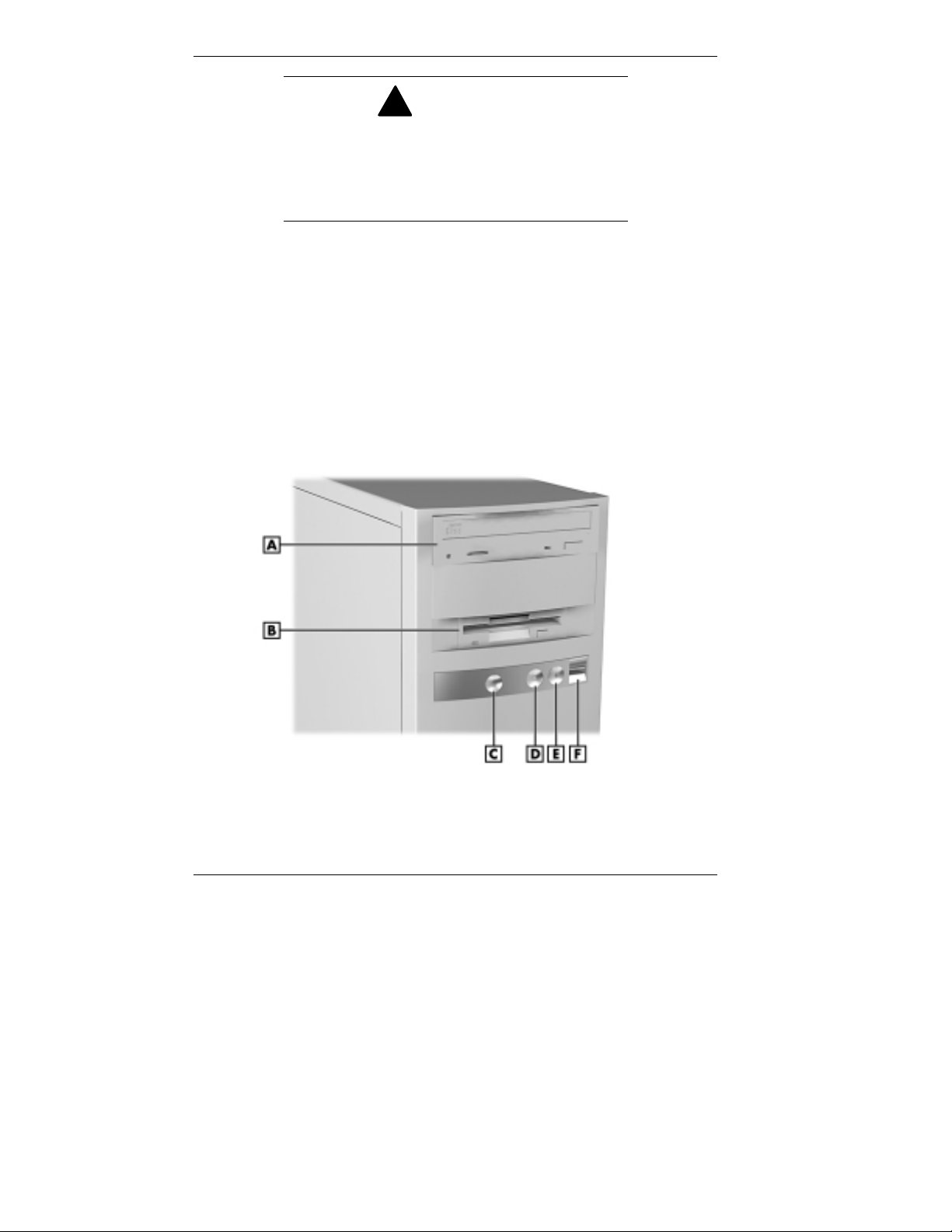
Front Features
The following figure shows the featur es on the front of the
syste m. A brie f description fo llow s the figure.
WARNING
Front features
A
– CD-ROM Drive
B
– Diskette Drive
C
– Power/Sleep Button
1-2 Reviewing Syst em Featu res
D
– Power/Sleep Lamp
E
– Hard Drive Lamp
F
– USB Port

System Controls and Lamps
System contro ls let you se lect specific system operat ions.
Lamps let you know the status of system operation. The
following describes the controls and lamps. The previous
figure shows the co nt ro ls and lamps o n the fro nt of the
system.
Power/Sleep button
Press this button to turn on system power. To turn off
power, press the button and hold in place until the system
powers down (approximately three to four seconds).
Press and immediat ely release t he power/sleep button to
suspend system operation when you plan to be away from
your computer for a short time. Th is place s the system in a
power saving mode. If you have a VESA-compliant
monitor, your monitor also goes into a power-saving
mode.
Press any key or move your mouse to resume system
operation at the point where you stopped it.
An amber system unit power lamp indicates that the
system is in a power-saving mode.
Power/Sleep lamp
The power/sleep lamp indicat es whet her s yst em power is
on or off. It also lets you know if the system is operating
in a power-saving mode.
A steady green lamp indicates that the power is on to all
system components. An amber lamp indicates that the
system is in Sleep mode with full-power reduction.
Reviewing System Features 1-3

Har d drive lamp
A lit lamp indicates that t he hard drive is active. The green
lamp tells you tha t the ha rd drive is read ing or writing
data.
Do not turn off the system unless absolutely
necessary whil e the hard drive lamp is lit. To do
so can damage your hard driv e or data.
Diskette Drive A
Use diskett e drive A to copy data files to and from a diskette.
You can also use it as a bootable drive for loading and
starting pro grams fro m a diskette.
To prevent damage to your disket te drive and
data, do not turn off the system or remove a
diskette while the diskette drive busy lamp is lit.
!
CAUTION
!
CAUTION
Universal Serial Bus Port
The universal serial bus (USB) port on the front of the system
allows you to easily and conveniently add plug and play USB
devices without opening up the system. You simply plug the
USB device into the port. You can connect up to 127 devices
including a mouse, monitor, keyboard, printer, scanner,
speakers, and more. A second USB port is on the rear of the
system.
1-4 Reviewing Syst em Featu res

CD-ROM Drive
Some models come with a 32X Max or 40X Max variable
speed CD-ROM drive. Use the CD-ROM drive to load and
start progr ams fro m a compact disc (CD). You can also use
the CD-ROM drive to play your audio CDs.
The CD-ROM drive operates at different speeds depending
on whether the CD you are using contains data or music. This
allows you to get your data faster and to see smoother
animation and video.
DVD-ROM Drive
Some models come with a 4X or 6X digital video disc
(DVD)-ROM drive (Windows 98 systems only). The drive
offers many improvement s over the standard CD-ROM
technology, including superior video and audio playback,
faster data access, and greater storage capacities.
The DVD-ROM drive uses DVD technology to read DVD
discs as well as standard audio and video CDs.
Tape Backup Unit
Some models come with a tape backup unit. If your system
has a tape backup unit, you can use it to quickly back up all
or part of your system’s files to a high-capacity tape
cartridge. Backup software helps you tailor the backup
process to protect your files and app lications. Files are
compressed during the backup process to conserve space and
to speed up the process.
Reviewing System Features 1-5

Zip Drive
Some models come wit h a Zip® drive. Use the Zip drive to
back up work, archive old files, and transport your work.
Store up to 100 MB of data on a 3 1/2-inch Zip disk.
PC Card Adapter
If your model has a PC card adapter, you can add PC cards to
the system. A PC card is insert ed into a PC card slot similar
to inserting a diskette in a diskett e drive.
Each type of PC card has a different function. With your PC
card adapter, you can add a number of functions to your
system with a variet y of PC cards.
LS-120 SuperDisk Drive
Some models come with an LS-120 MB SuperDisk™ dr ive, in
place of the 3 1/2-inch diskette drive. The drive offers highcapacity, removable data sto r age through use o f SuperDisk
diskettes that hold up to 120 MB of data. The SuperDisk
drive is fully compatible with 1.44 MB disket tes and can read
or write to the diskettes.
1-6 Reviewing Syst em Featu res

Rear Features
On the rear of your computer, you’ll find external connectors,
the power supply socket and voltage select switch, and
expansion board slots. The following figure shows the
features.
Rear features
A
– Power Socket
B
– Voltage Selector Switch
C
– Mous e Port
D
– Keyboard Port
E
– USB Port
F
– Serial Port 1
G
– Serial Port 2
H
– Line Out Jack
I
– Line In Jack
J
– Microphone In Jack
K
– Fan
L
– Printer Po rt
M
– MIDI Port
N
– VGA Monitor Connector
O
– Expansion Slots
Reviewing System Features 1-7

External Connectors
External connecto r s let you att ach periphera l devices, such as
a monitor, keyboard, mouse, and printer to your system. Your
system has the fo llowing exter na l co nnect ors.
Mouse port
Attach the mouse that comes w ith your computer to this
port. The mouse port supports a PS/2-compatible mouse.
Keyboard port
Attach the keyboard that comes with your computer to the
ke yboard port.
The keyboard port supports a PS/2®-compatible (personal
system/2-compatible) 101-key or 104-key keyboard (in the
U.S. and Canada) or a 102-key keyboard (in the United
Kingdom and Germany) with a 6-pin mini DIN connector.
VGA monitor connector
The system comes with an acce lerated graphics port
(AGP) graphics board. The external video graphics array
(VGA) connector on the AGP board supports an NEC
MultiSync® monitor , NEC VistaScan™ monitor, or other
VGA-compatible monitor with a 15-pin connector. Att ach
the signal cable from your monitor to the VGA connector.
Printer port
Use this port to connect a parallel printer with a 25-pin
connector to the system.
Serial ports 1 and 2 (COM1 and COM2)
Attach a serial device with a 9-pin connector to these
serial ports. Serial devices include a pointing device, serial
printer, or a modem.
Unive rsal Se rial Bus port
This port adds a USB connector at the rear of the system
(see “Universal Serial Bus Port” earlier in this chapter) .
1-8 Reviewing Syst em Featu res

Audio connectors
The following connector s co me integrat ed o n t he syste m
board (see the preceding figure for jack locations).
Microphone in jack
The microphone in jack lets you connect a microphone
for recording audio information in your data s ystem
files.
Line in jac k
The line in jack lets you connect a stereo audio device
suc h a s a stereo amp lifier or a ca s s e tte o r minidisc
player for playback or recording.
Line out jack
The line out jack allows you to connect an amplified
output device, such as powered speakers or headset, a
stereo tape recorder, or an external amplifier for audio
output.
MIDI/Joyst ick co nnect or
The MIDI/Joystick connector lets you attach a joystick to
your system for use with games.
Fax/modem ports
Some models come with a V.90 rated 56-kilobytes per
second (Kbps) fax/mo dem board. The fax/mo dem boa rd
allows the connection of a phone line to the computer for
fax and data communications functions.
Dual fax/modem ports let you use a telephone line for the
fax/modem and your telephone.
LAN connector
Some models come with a networ k board. Use the RJ-45
compatible port on the board for connect ing the system to
an Ethernet local-area net work (LAN).
Reviewing System Features 1-9

Power Supply Features
Your system has the following power supply features:
Power socket
Connect your power cable to t his socket .
Voltage selector switch
Sets the voltage for your system to 115 volts or 220 volts.
!
Set the switch cor r ectly for the voltage in your
area. Most wall outlets in the United States and
Canada are 115 volts. O utlets in Europe,
Australi a, and Asi a ( ex c ept T aiwan) are
230 volts. Tai wan uses 115-volt outlets.
Pow e r supply fa n
The power supply fan cools the power supply and other
system component s to keep t hem from overheating. Keep
the area near the fan clear for proper vent ilat ion.
CAUTION
Inside Features
See the following figure for the location of features w ithin the
system. Feature descriptions follow.
1-10 Reviewing System Features
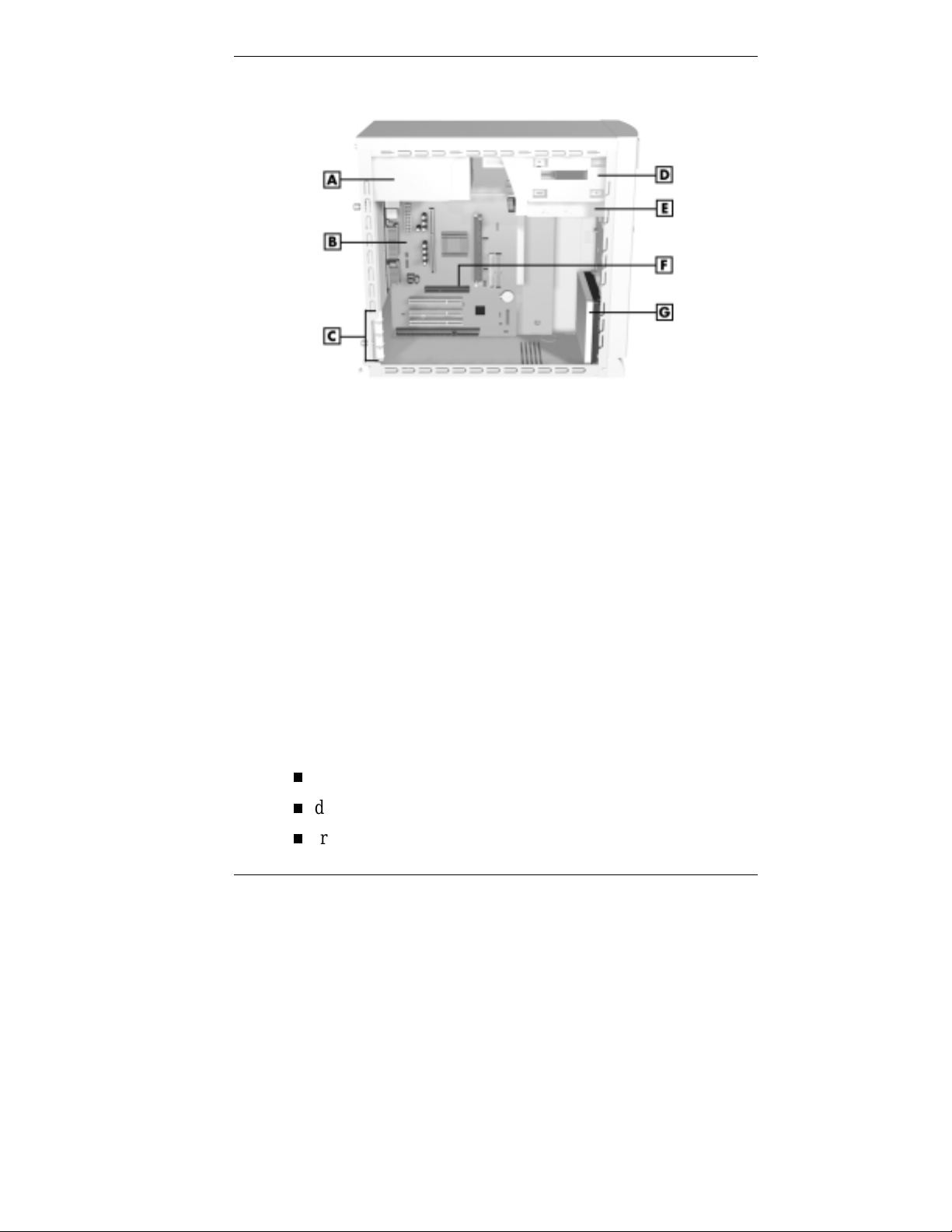
Inside the system
A
– Power Supply
B
– System Board
C
– Expansion Slots
D
– Accessible Device Bays
System Board
The syste m processor, memory, audio subsystem, s yst em
battery, internal connecto r s, and externa l connectors are on
the system board. For information on the external connector s,
see “External Connecto rs” earlier in this chapter.
The system board supports a diskette drive and up to four
IDE devices such as IDE hard drives, IDE CD-ROM drive,
IDE DVD-ROM drive, and IDE Zip drive.
Internal connecto r s on the system board include:
primary and secondary IDE co nnectors
diskette drive connect or
front panel connectors for lamp, USB, and audio signals
E
– Diskette Drive
F
– AGP Board Connector
G
– Hard Drive
Reviewing System Features 1-11

power connector s
AGP graphics board connector
three PCI connecto r s
one ISA connector
additional connectors include the CD Audio In, Modem
In, Wake-On LAN, and fan.
Network Board
Some models come wit h a 3 Co m® 10/100Base-T Ethernet
net work boar d, an Intel® EtherE xpress® Pro100 +10/100
Ethernet network board, or a GVC D110G 10/100 network
board installe d in a PC I slot .
Modem Board
Some models come wit h a Robotics® 56K Python V.90 ISA
modem board or a Lucent V.90 Winmodem PCI board.
Connect your telephone line to th is board.
Storage Device Support
Five storage device bays accommodat e up to three accessib le
devices and two internal hard drives.
Chassis
The NEC micro tower chassis conforms to the Intel ATX
form factor specificat ion. The c hass is features the following:
standardized chassis s ize and d imensions
standardized system board size and dimensions
standardized ATX 145 watt power supply.
1-12 Reviewing System Features

Speakers
If ordered, some systems come with two high-quality stereo
speakers. One of the speakers connects to the line out jack at
the rear of the system unit.
An AC adapter comes with the speakers. I n stall the AC
adapter along with the speakers.
Adjust the speaker volume by using the vo lume cont ro l on
the front of the syste m or on the right speaker . Yo u can also
use the Windows sound software. To bring up the Windows
volume control, double click the speaker icon on the t askbar
(next to the syste m clock). Use the software to balance the
sound between the left and right speaker s.
System Features
Your computer hardware and software deliver the
performance and technologies you need for all your
challenging tasks today and into the future.
Hardware
The PowerMate VT 300 Series includes the following
hardware features:
PC98 Compliance
All the hardware in the system has been certified by
Microsoft® to be PC98 compliant.
Processor
The system comes with a Celeron® processor, Pentium® II
processor, or Pentium III processor. Processor speed
depends o n s yst em model. The processors are fast,
power ful pro cessors that lend t he mse lves to
computational, graphical, and networking tasks.
Reviewing System Features 1-13

Audio on the System Board
The system board comes w ith an audio subs yst em. The
audio chipset gives you a surrou nd sound system for threedimensio nal sou nd effe c ts — much like a live
per formance. It also provides wavetable synthesis.
(Wavetable synthes is uses actual recordings of real sound
effects and musical instr uments for a dynamic audio
experience.)
Flashable ROM BIOS
The system’s ROM BIOS features system setu p
configuration, Plug and Play support, and flash support for
easy and economical BIOS upgrades.
System Memory
Your computer comes with at least 32 MB o f non-ECC
synchronous dynamic random access memory (SDRAM)
and supports up to 512 MB.
AGP Graphics Board
All models ship with an AGP gr aphics board. AGP
enhances graphics performance, particularly for 3-D
applications.
Po wer Manageme nt Options
Power management opt ions conserve energy and reduce
power costs.
Software
NEC CSD provides a variety o f applicat ions and hardware
utilities with your system to let you take advantage of your
hardware capabilities.
Preloaded Operating System
The Microsoft® Windows NT®, Windows® 95, or Windows
98 operating system comes loaded o n your syst em.
1-14 Reviewing System Features

NEC OS Restore CD
In the event of operat ing system problems, you can rest ore
your operating system using the NEC OS Restore CD. The
NEC OS Restore Program on the CD provides a “Fix OS”
Restore option for reinstalling the Windows 95 or
Windows 98 operating system while leaving data files intact.
This feature lets you back up your data files before
performing a complete restore of the operating system.
The OS Restore program also provides options for
reformatting and repartitioning the hard drive. In addition, the
program automatically deter mines which dr ivers are needed
for your original hardware configuration and insta lls them
during the restore.
NEC Application and Driver CD
Your system comes with an NEC Application and Driver CD.
Use this CD to install any or all of the software that comes
with your system, including:
Microsoft® Internet Explorer
Internet Exp lorer prov ides a t op-no tch browse r with
preloaded links for easy access to t he world wide web.
Also use Internet E xplorer to access one of the many new
browser-based utilities.
Netscape® Browser
Netscape provides a top-notch browser with preloaded
links for easy access to the wor ld wide web. Also use
Netscape to access o ne of the many new browser - based
utilities.
Reviewing System Features 1-15

Adobe® Acrobat® Reader
Use the Adobe Acrobat Reader to read and print portable
document format (PDF) files found on the Internet and
PDF documents included with various software
applications.
Network™ Assoc iat es VirusScan® Software
Protect the system from viru ses by running VirusScan.
PartitionMagic™
Repartition your hard drive while leaving your data intact
with PartitionMagic. Includes BootMagic™ software for
eas il y mana g in g multip le op er a t ing systems.
NEC Help Center
The NEC Help Center is an online guide with information
about the Power Mate system.
Healthy Environment
This is an online version of the printed brochure, Setting
up a Healthy Environment.
The NEC Applicat ion and Driver CD also contains a wide
selection of dr ivers for hardwar e that is compatible with
PowerMate series co mputers. These drivers are provided with
the original manufacturer’s inst allation wizard s t o ensure
correct inst allation.
Security
The system has hardware, software, and mechanical securit y
features that offer protection against unauthorized access to
your system and data. The following security featur es ar e
available with the syst em.
Passwor d security
The BIOS Setup utility includes a feature t hat lets you set
up either a user or supervisor password, or both.
1-16 Reviewing System Features

The user password controls booting of the system and
controls access to the Setup utility and the keyboard. (User
access to the BIOS Setup utility is limited to a subset o f all
BIOS Setup parameters when a supervisor password has
been set .)
The supervisor password allows full access to t he system
and the BIOS.
Windows network secur it y features
To learn more about the network security features
available through the Windows operating system, refer to
your Windows documentation or consult your system
administrator.
Locking tab
The system also has a lock ing tab o n the rear of the
chassis. The tab fits through a slot on t he rear edge of the
chassis cover when the co ver is on. When a pad lock is
used in the tab, the system is physically prot ected from
chassis intrusion.
Reviewing System Features 1-17
 Loading...