

The Space-Saving Office PC
POWERMATE®ES SLIMLINE SERIES
USER’S GUIDE

Proprietary Not ice and Liability Disclaimer
The information disclosed in this document, including all designs and related
materials, is the valuable property of NEC Computers Inc. (hereinafter “NECC”)
and/or its licensors. NECC and/or its licensors, as appropriate, reserve all patent,
copyright and other proprietary rights to this document, including all design,
manu fact urin g, repr odu cti on, u se, and sa l es right s th er et o, excep t to the ex t ent sai d
righ ts are expressly granted to others.
The NE CC product(s) discussed in this document ar e warranted in accordance with
the ter m s of the War ran ty Sta t emen t a ccomp an yin g ea ch pr odu ct. However , a ctua l
performance of each such product is dependent upon factors such as system
configuration, customer data, and operator control. Since implementation by
customers of each product may vary, the suitability of specific product
configurations and applications must be determined by the customer and is not
warranted by NECC.
To allow for design and specification improvements, the information in this
document is subject to change at any time, without notice. Reproduction
of this document or portions thereof without prior written approval of
NECC is prohibited.
NEC is a registered trademark of NEC Corporation.
PowerMate an d MultiSync are registered trademarks and VistaS can is a trademark of NEC
Corporation or one of its subsidiaries. All are used under license by NEC Corporation
and /or one or more of its s u bsidiaries.
All other trademarks and registered trademarks are the property of their respective
trademark own ers.
First Printing — May 2000
Copyright 2000
NEC Computers Inc.
15 Business Park Way
Sacramento, CA 95828
All Rights Reserved

Contents
Using This Guide
Text Conventions.................................................................................... viii
Related Documents................................................................................... ix
1 Reviewing System Features
Front Features ......................................................................................... 1-2
System Controls and Lamps ............................................................ 1-4
Diskette Drive................................................................................. 1-5
Universal Serial Bus Port................................................................ 1-5
CD-ROM Drive.............................................................................. 1-6
DVD-ROM Drive........................................................................... 1-6
Audio Connectors........................................................................... 1-6
Rear Features.......................................................................................... 1-7
Exter na l C onnectors........................................................................ 1-8
Power Supply Features.................................................................... 1-9
Interior Features.................................................................................... 1-10
System Board ............................................................................... 1-11
Riser Board..................................................................................1-11
Local Area Network...................................................................... 1-11
Storage Device Support ................................................................ 1-11
Chassis ................................................................................................. 1-12
Optional Speakers................................................................................. 1-12
System Overview.................................................................................. 1-12
Hardware...................................................................................... 1-12
Software....................................................................................... 1-13
Preloaded Software............................................................... 1-13
NEC OS Restore CD ............................................................ 1-14
NEC Application and Driver CD........................................... 1-15
Security........................................................................................ 1-15
2 Setting Up the System
Slimtower Setup ..................................................................................... 2-2
Cable Connections.................................................................................. 2-3
Startup.................................................................................................... 2-4
Shutdown................................................................................................2-4
Power-Saving Operation......................................................................... 2-5
Content s iii

System Care ............................................................................................2-6
Protecting Your System From Damage............................................2-6
Keeping Your System in Good Condition ........................................2-7
Moving or Shipping Your System....................................................2-8
More Information ....................................................................................2-9
3 Configuring the System
Configuration Tools and Utilities.............................................................3-2
BIOS Setup Utility...................................................................................3-4
How to Start BIOS Setup.................................................................3-4
How to Use Setup............................................................................3-5
Main Menu......................................................................................3-6
Advanced Menu ............................................................................3-10
Security Menu...............................................................................3-19
Exit Menu .....................................................................................3-20
FLASH Utility.......................................................................................3-20
NEC INFO Center.................................................................................3-21
NEC Application and Driver CD............................................................3-23
NEC OS Restore CD..............................................................................3-24
System Board Jumper Settings...............................................................3-25
Intel Processor Serial Number Control Utility.........................................3-29
System Requirements ....................................................................3-29
Installation ....................................................................................3-29
Processor Serial Number................................................................ 3-30
Frequently Asked Questions ..........................................................3-30
Technical Support..........................................................................3-31
4 Installing System Upgrad es
General Rules..........................................................................................4-2
Safety Precautions...................................................................................4-2
System Cover ..........................................................................................4-3
Removing the Cover........................................................................4-4
Replacing the Cover ........................................................................4-5
System Board Upgrades...........................................................................4-6
Memory Upgrade ............................................................................4-7
Checking System Memory .......................................................4-8
Removing a DIMM.................................................................4-9
Instal ling a DIMM.................................................................4-10
Processor Upgrade.........................................................................4-11
Removing the Processor ........................................................ 4-12
Installing an Upgrade Processor .............................................4-14
iv Contents

Expansion Boards................................................................................. 4-15
Instal ling an Expansion Board....................................................... 4-16
Remo ving an Exp ansion B oard..................................................... 4-18
Data Storage Devices............................................................................ 4-18
Connecting Device Cables ............................................................ 4-19
Replaci ng the 5 1/4-Inch Accessible D evice.................................. 4-19
Removing the 5 1/4- Inch Accessible Device.......................... 4-19
Installing a 5 1/4-Inch Accessible Device.............................. 4-22
Replacing the 3 1/2-Inch Diskette Drive........................................ 4-23
Removing the 3 1/2-Inch Diskette Drive ............................... 4-23
Installing the 3 1/2-Inch Diskette Drive................................. 4-25
Replacing the 3 1/2-Inch Hard Drive ............................................. 4-26
Removing the 3 1/2-Inch Hard Drive..................................... 4-26
Installing the 3 1/2-Inch Hard Drive...................................... 4-27
5 Solving System Problems
Solutions to Common Problems.............................................................. 5-2
System Problems............................................................................ 5-2
Diskette Drive Problems................................................................. 5-4
Monitor Problems ........................................................................... 5-5
Keyboard/Mouse Problems............................................................. 5-6
CD-ROM Drive Problems............................................................... 5-6
Speaker Problems........................................................................... 5-7
How to Clean the Mouse......................................................................... 5-8
How to Replace the CMOS Battery....................................................... 5-10
6 Getting Services and Support
NECC Website ....................................................................................... 6-2
NECC FTP Site ...................................................................................... 6-3
Email/Fax Technical Support Service ...................................................... 6-3
NECC Technical Support Services .......................................................... 6-4
A Setting Up a Healthy Work Environment
Making Your Computer Work for You....................................................A-2
Arrange Your Equipment........................................................................A-3
Adjust Your Chair...................................................................................A-4
Adjust Your Input Devices......................................................................A-6
Adjust Your Monitor...............................................................................A-8
Vary Your Workday..............................................................................A-10
Pre-existing Conditions and Psychosocial Factors..................................A-11
Content s v

Checking Your Comfort: How Do You Measure Up? ............................A-11
Checking Your Chair....................................................................A-11
Checking Your Keyboard.............................................................A-12
Checking Your Mouse..................................................................A-12
Checking Your Monitor................................................................A-12
Checking You...............................................................................A-12
B System Specification s
System Board .........................................................................................B-2
System Processor............................................................................B-2
Random Access Memory (RAM)....................................................B-2
Cache Memory...............................................................................B-2
Read Only Memory (ROM)............................................................B-2
Calendar Clock...............................................................................B-3
Input/Output (I/O) Features.............................................................B-3
Video Memory ...............................................................................B-4
Sound Controller............................................................................B-4
Local Area Network .......................................................................B-4
Graphics Controller ........................................................................B-4
System Peripherals..................................................................................B-5
Keyboard........................................................................................B-5
Mouse ............................................................................................B-5
Diskette Drive ................................................................................B-5
Hard Drive.....................................................................................B-6
CD-ROM Drive..............................................................................B-6
DVD Drive .....................................................................................B-6
Optional Speaker Set ......................................................................B-6
Dimensions.............................................................................................B-6
System ...........................................................................................B-6
Keyboard........................................................................................B-6
Power.....................................................................................................B-7
Opera t ing Env ironment...........................................................................B-7
Compliance............................................................................................B-7
Index
Regulatory St at ements
vi Contents

Using This Guide
The PowerMate® ES Sli m Line Series User’s Guide provides a
comprehensive reference to information about your system.
The gui d e contains th e following in formation:
Chapter 1, Reviewing System Features, provides a look at the front,
back, and inside features of the system. It also gives a summar y of the
system’s hardware, software, and secu r ity features.
Chapter 2, Setting Up the System, briefly describes how to set up, start
up, and shut down the system. The chapter also provides information
on in st al ling applications and ti p s on caring for the system.
Chapter 3, Configuring the System, describes how to use the software
utilities shipped with your system, including the BIOS Setup Utility,
FLASH Utility, NEC INFO Center, NEC Application and Driver CD,
NEC OS Restore CD, and In tel Processor Serial Number C on trol
Utility. The chapter also includes information for setting system
jumpers.
Chapter 4, Installing System Upgrades, provides installation
procedures for processor, memory, expansion board, and storage
device upgrades.
Chapter 5, S olving S ystem Problems, cont a ins trou bleshooting tips for
solving simple problems. The chapter also includes procedures for
cleaning the mouse an d replacing the system batt er y.
Chapter 6, Getting Services and Support, describes the services
available to you for informati on an d h elp, and describes how to access
the services.
Appendix A, Setting Up a Healthy Work Environment, contains
guidelines to help you use your computer productively and safely.
This appendix also instructs you on how to set up and use your
computer to reduce your risk of developing nerve, muscle, or tendon
disorders.
Appen dix B, System Speci fi cations, provides technical speci fi cations
for your system and its components.
Using This Guide vii
wor kstation may pose a risk of serious inju ry. To red uce you r risk of i njury,
set up and us e your com puter in the ma nner described in Appendix A,
Setting Up a Healthy Work Environment.
Text Conventions
This guide uses the following text conventions.
Warnings, cauti ons , and notes have the followin g m ean ings:
in serious personal injury or loss of life.
hardware or software.
Prolonged or improper use of a computer
Warnings alert you to situations that could result
Cautions indicate situations that can damage the
Note
described.
Notes give important information about the material being
Names of keyb oard keys are printed as they ap pear on the keyboa rd,
for example,
Text or keystrokes that you enter appear in boldface type. For
example, type
File names are printed in uppercase letters. For example,
AUTOEXEC.BAT.
viii Using This Guide
Ctrl, Alt
abc123
Enter
, or
and press
.
Enter
.

Related Documents
In addition to this guide, the following printed documentation ships with
your system.
NEC PowerMate ES SlimLine Series Quick Setup/Quick Reference
The Quick Setup shows h ow to q u ickly get the s yst em connected and
powered on.
The Quick Reference briefly describes the documentation, NEC
utilities, software applications, and services available with the NEC
PowerMate ES SlimLin e Series system .
How Does Your Workplace Measure Up?
This broch ure provides information for setting up and using the
computer productively and safely. Information includes guidelines to
redu ce the risk of injury associat ed wi th using a computer.
NEC PowerMate ES SlimLine Series Release Notes
Release Notes provide additional information about the computer that
was not available at the time the user’s guide was printed. Information
in the Release Notes is the result of extensive product testing.
Your system also comes with th e NEC INFO Center online
documentation on your hard drive. The NEC INFO Center is an online
guide to your PowerMate system. It provides information about the
system through the following online modules: Tour, User’s Guide,
Questions, Solutions, and Services.
In addition to the documentation that ships with the system,
documentation is available from the NECC website.
NEC PowerMate ES SlimLine Series Service and Reference Manual
This manual provid es information for ma intain i ng, troubleshooting,
and repairing the system. This manual also includes hardware and
interface information for programmers, engineers, and others who
need t o know how the system is designed.
Service and reference manuals are available on the Intern et at the
Service and Support area of the NECC website (see Chapter 6 for
access information).
NEC Po werM a te ES SlimLi ne S eries User’s Guide
Ch e ck the website for the mos t current online version of your printed
user’s guide.
Using This Guide ix

Reviewing System Features
Front Features
Rear Features
Interior Features
Chassis
Optional Speakers
System Overview
1

wor kstation may pose a risk of serious inju ry. To red uce you r risk of i njury,
set up and use the computer in the manner described in Appendix A,
Setting Up a Healthy Work Environment.
This chapter highlights system hardware and software, and describes the
security features of the system.
Front Features
Your PowerMate ES SlimLine Series system can be used as a slimtower
or as a desktop system. The following figures show the features on the
front of the system for both configurations. Brief descriptions follow the
figures.
Prolonged or improper use of a computer
1-2 Reviewing S ystem Feat ures
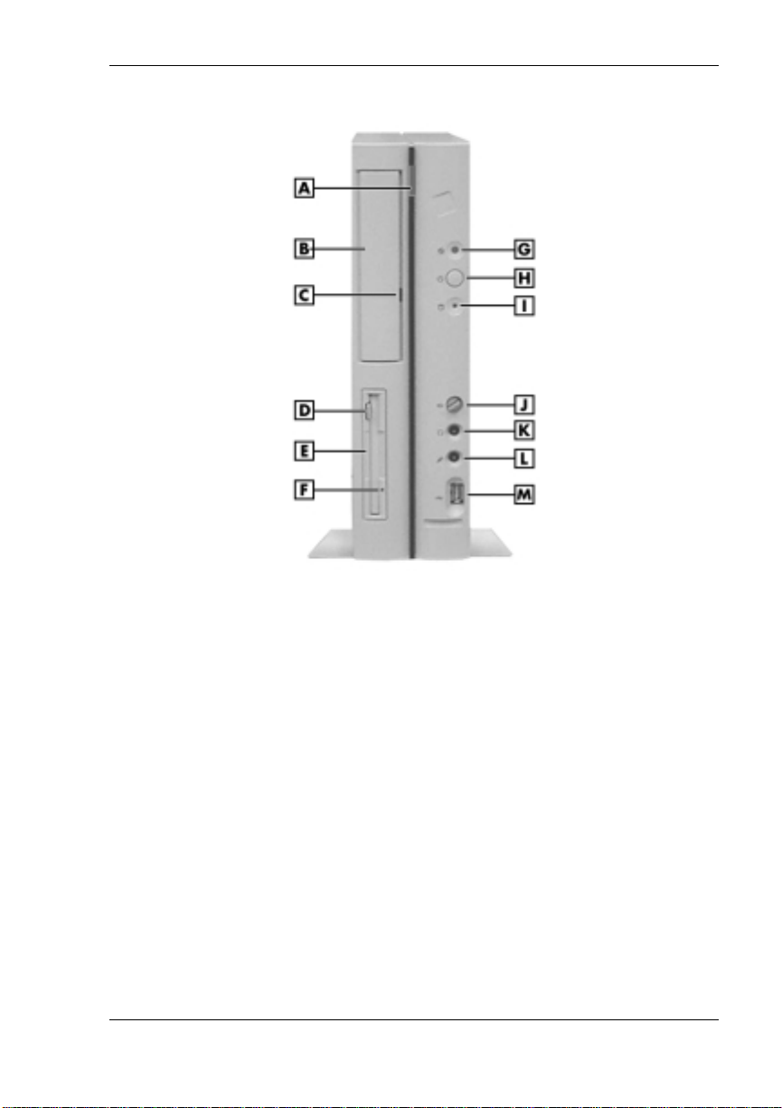
PowerMat e ES Slim Li n e Ser ies slimtower fr on t features
A
– CD-ROM Tray Open/Close Button
B
– CD-ROM Drive
C
– CD-ROM Drive Activity Lamp
D
– Diskette Drive Disk Eject Button
E
– Diskette Drive
F
– Diskette Drive Activity Lamp
G
– Po w er/Sleep Lamp
H
– Power/Sleep Button
I
– Hard Drive Activity Lamp
J
– Volume Control
K
– Headphone Jack
L
– Microphone Jack
M
– USB Po r t
Reviewing Sys tem Features 1-3
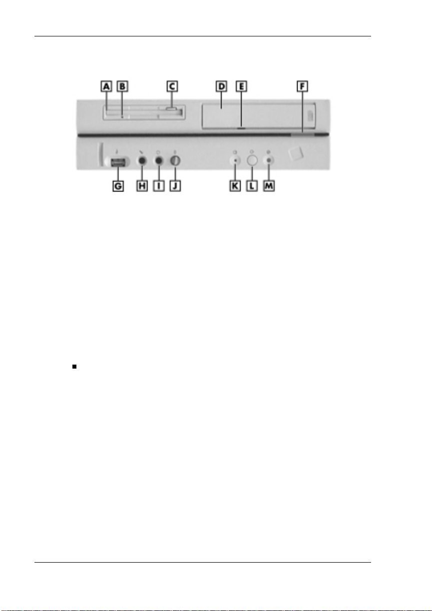
PowerMat e ES Slim Li n e Ser ies desktop front features
A
– Diskette Drive
B
– Diskette Drive Act ivity Lamp
C
– Diskette Drive Di sk Eject Button
D
– CD-ROM Drive
E
– CD-ROM Drive Activity Lamp
F
– CD-ROM Tray Open/Close Button
G
– USB Port
System Controls and Lamps
System controls an d la mps are identi cal for both set u p s. Th e controls and
lamps include a power/sleep button, power/sleep lamp, and hard drive
activity lamp.
Power/Sleep but t on
Press this button to turn on system power. To turn off power, close all
applications and shut down Windows. If you have Windows 98 or
Windows 2000, the system automatically powers down. If you have
Wind ows NT , close all appl ications, sh ut down Windows NT, and
press in th e power button un til the system po wers down
(approximately four seconds).
Press and immediat ely release th e p ower/sleep but ton to suspend
syste m operation and go int o the power savin g mode. If you ha ve a
VESA-compliant monitor, your monitor also goes into a power-saving
mode.
An amber s ystem unit power/sleep lamp indicates that the system is in
a power-saving mode.
H
– Microphone Jack
I
– Headphone Jack
J
– Volume Co n trol
K
– Hard Drive Activity Lamp
L
– Power/Sleep Button
M
– Power/Sleep Lamp
Move th e mou se or press a key on th e k eyb oa rd to exit th e power
saving mode and resume system operation.
1-4 Reviewing S ystem Feat ures
Power/Sleep lamp
The power /sleep lamp indicates wh ether system po wer is on or off. It
also lets you know if the system is operating in a power-saving mode.
A steady green lamp indicates that the power is on to all system
components. An amber lamp indicates that the system is in sleep mode
with full-power reduction.
Hard drive lamp
A lit lamp ind icates tha t the hard driv e is active . The green lam p tells
you that the ha rd dri ve is readi ng or wri ting dat a.
necessary while the hard drive lamp is lit. To do so can damage your hard
drive or data.
Diskette Drive
Use the diskette drive to copy data files to and from a diskette. You can
also use it as a boota ble drive for loading and start ing programs from a
diskette.
data, do not turn off the system or remove a diskette while the diskette
drive busy lam p is lit.
Do not turn off the system unless absolutely
To p revent damage t o your di skette d rive and
Universal Serial Bus Port
The universal serial bus (USB) por t on the front of the system allows you
to easily and conveniently add plug-and-play USB devices without
opening up the system. You simply plug the USB device into the port.
You can connect up to 127 devices including a mouse, monitor, keyboard,
printer, scanner, speakers, and more. A second USB port is on the rear of
the syst em.
Reviewing Sys tem Features 1-5

CD-ROM Drive
Systems come with a 40X Max or higher variable speed CD-ROM drive.
Use th e CD-ROM drive to loa d and start programs from a compact disc
(CD). You can also use th e CD- ROM drive to play your audio CDs.
The CD-ROM drive oper ates at different speeds dep ending on whether
the CD you are using cont ains data or music. This allows you t o get your
data faster and to see smoother animation and video.
DVD-ROM Drive
Some system s might come with an 8X or hi gher digital video disc
(DVD)-ROM drive. The drive offers many improvements over the
standard CD-ROM technology, including superior video and audio
playba ck , faster dat a acces s, and gr eater storage cap acities.
The DVD-ROM drive uses DVD technolog y to read DVD discs as well as
standard a udio and video CDs .
Audio Connectors
Your system has the following audio connectors an d a volu me control on
the fr on t of the system.
Micr ophone jack
Use thi s jack to connect a mi crophone for r ecording audio informati on
in your data files.
Headphone jack
Use thi s jack to connect an op tional headphone set. Pl ugging in the
headphone set disables the speak ers.
Volume control
Use this control to adjust the volume of the optional headphone set.
You can also use the Windows sound software. To bring up the
Windows volume control, double click the speaker icon in the taskbar
(nex t to the system clock) . Use the software to balance the sound
between the left and right s peaker s .
1-6 Reviewing S ystem Feat ures
Rear Features
On the rear of your compu ter, you’ll find external con nectors, the power
supply socket, a voltage switch, and expansion board slots. The following
figures show the features.
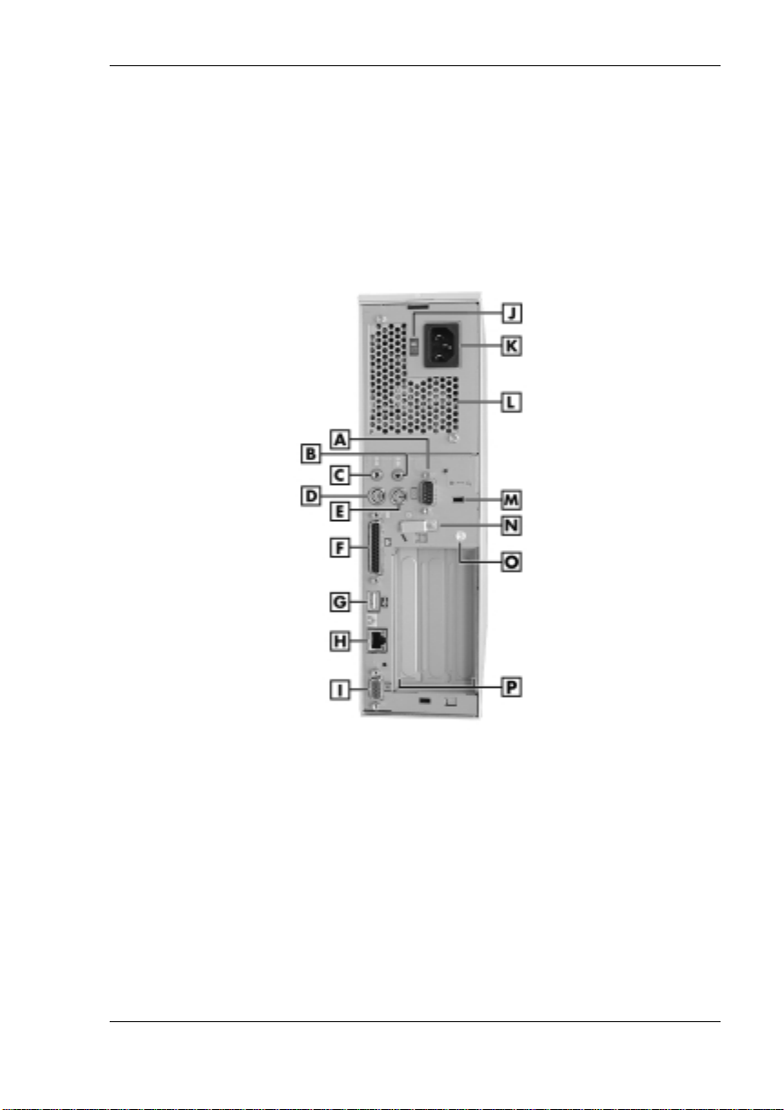
PowerMate ES SlimLine Series slimtower rear features
A
– Serial Port
B
– Line Out Jack
C
– Line In Jack
D
– Keyboard Port
E
– Mouse Port
F
– Parallel Port
G
– USB Port
H
– LAN Port
I
– VGA Port
J
– Voltage Switch
K
– AC Power Connector
L
– Power Supply
M
– Kensington Lock Slot
N
– Keyboard/Mouse Anti-theft Bracket
O
– Anti-Theft Rin g
P
– Expansion Slots
Reviewing Sys tem Features 1-7

PowerMate ES SlimLine Series desktop rear features
A
– AC Power Connector
B
– Power Supply
C
– Kensington Lock Slot
D
– Keyboard/Mouse Anti-theft Bracket
E
– Anti-Theft Ri n g
F
– Expansion Slots
G
– Voltage Switch
H
– VGA P ort
External Connectors
External connect ors let you attach peripheral d evi ces , such as a monitor,
keyboard, mouse, and printer to you r system . Your system has the
follo wing external connector s.
Mouse port
Attach the mouse that comes with your computer to this port. The
mouse port supports a PS/2-compatible mouse.
Keyb oard port
Attach the PS/2
to the keyboard port.
VGA monitor connector
The syst em comes with an a ccelerated graphics port ( AG P ) in tegrated
on th e system board and por ted to the exter n al video graphics array
(VGA) connector on th e board. The VGA connector su ppor t s an NEC
MultiSync
VGA-compatible moni t or with a 15-pin connector. Attach your
monitor’s signal cable to the V G A connector.
®
®
monitor, NEC VistaScan™ monitor, or other
I
– Line Out Jack
J
– Line In Jack
K
– Keyboard Port
L
– Mous e Port
M
– Parallel Port
N
– USB Port
O
– LAN Port
P
– Serial Port
-compatible keyboa rd that comes wi th your c omputer
1-8 Reviewing S ystem Feat ures

Printer port
Use thi s p or t to connect a par allel printer with a 25-pin connector to
the syst em.
Se ri al port (COM1 )
Atta ch a serial device wit h a 9-pin connector to this serial port. Serial
devices include a pointing device, s erial print er, or a modem.
Universal Seria l Bus port
This port adds a USB capability at the rear of the system (see
“Universal Serial Bus Port” ear lier in this ch apter).
Audio connector s
The syst em comes with s oun d integrated on the system board. The
follo wing connectors come integrated on th e board (see the preceding
figures for jack locations).
— Line in jack
The lin e in jack lets you con nect a stereo a u di o d evi ce such as a
ster eo a mplifier or a ca s sette or minidisc player for playback or
recording.
— Line ou t jack
The line out jack allows you to connect optional spea kers, an
amplified output device such as powered speakers, a stereo tape
recor d er , or an externa l am pl ifier for audio output.
LAN port
All systems come with local area network (LAN) int egrated on th e
system b oa rd. Use the RJ-4 5 compatible LAN port on the board for
conn ecting the system to an Ethernet LA N .
Power Supply Features
The system has the following power supply features:
Power sock et
Connect your power ca bl e to this socket.
Voltage switch
Sets the voltage for your system to 115 volts or 230 volts.
area. Most wall outlets in the Uni ted States and Canada are 115 volts.
Outlets in Europe are 230 volts.
Set the switch correctly for the voltage in your
Reviewing Sys tem Features 1-9
Power connectors
The power supply has four power connectors that connect to the
dis kette dr ive, system board, and two stor age devices.
Power supply fan
The power supply fan cools the power supply and other system
components to keep them from overh eating. Keep th e area near the
fan cl ear for proper ventilation .
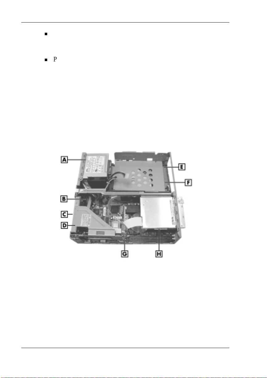
Interior Features
See the following figure for the location of features within the system.
Feature descriptions follow.
Inside the system
A
– Power Supply
B
– System Board
C
– Expansion Slots
D
– Riser Board Bracket
1-10 Reviewing S ystem Feat ures
E
– Hard D r ive (under support plate)
F
– CD-ROM Drive (not shown)
G
– DIMM Memory Socket s
H
– Diskette Drive

System Board
The syst em processor, memory, system battery, internal connectors, and
external connect ors are on the system b oard. For information on the
external connect ors, see “External Connectors” earlier in this chapter.
The syst em board supports a diskett e drive, an IDE hard drive, and an
IDE CD-ROM drive (or IDE DVD-ROM drive on some systems).
Inter n al connector s on th e s ystem board in clude:
primary and secondary IDE connect ors
diskette drive connector
front panel connectors for system lamps and USB
power connector s
AGP graphics connector ( VGA)
riser boa rd connect or
additional connectors include Wake-On LAN and fan.
Riser Board
All systems come with a riser board attached to a removable riser board
brack et. The riser board has three PC I connectors for ad ding up to three
optional e xpansion boar ds. The r iser board plug s into the riser board
conn ector on the system board.
Local Area Network
All systems come with a 3COM local area n etwork (LAN) ch i p in tegrated
on th e system board. Connect your network cable to th e LA N connector
on th e rear of the system.
Storage Device Support
Three storage device bays accommoda te up to two accessible devices
(diskette drive and CD-ROM drive or DVD drive) and one internal hard
drive.
Reviewing Sys tem Features 1-11

Chassis
The chassis is an NEC prop r ietary desig n wi th the following features:
stan dardized cha ss is size and dimen sions
stan dardized system b oa rd size and dimensions
standardized ATX 106-watt power supply
convertible to slimtower or desktop orientation.
The syst em can be placed in the slimtower or desktop p osition. Choose
the position that best suits your space.
Optional Speakers
When ord ered, two high-quality stereo speakers come with the system.
One sp eaker connects to the line out ja ck at the rear of th e system unit.
An AC adap ter and connect ing cables come with the speak ers. Install the
AC adap ter and cables al ong with the speakers.
Adjust the speaker volume by using th e vol u me control on th e s p eaker.
You can also use the Windows sound software. To bring up the Windows
volume control, double click the speaker icon on the taskbar (next to the
system cl ock). Use the software to balance the sound between th e left and
right speakers.
System Overview
See the following sections for a quick overview of system hardware,
software, and security features.
Hardware
The syst em includes the followin g hardware feat ures.
PC99 Compliance
All th e hardware in th e s ystem has been cert ified by Microsoft
PC99 compliant.
1-12 Reviewing S ystem Feat ures
®
to be

Processor
The syst em comes with an Intel
pr oc essor with a 66-MHz or hi gher fr ont side bus (FSB) or a
Pentium
®
III 5 33-MHz or higher process or with a 100-M Hz or high e r
®
Celeron™ 500-MHz or higher
FSB. Processor speed and FSB depend on s ystem model.
Audio features
The syst em comes with s oun d integrated on the system board. The
audio chipset gives you a surround sound system for
three-dimensi onal sound effect s . It also provi des wavetable synthes is.
(Wavetable synthesis uses actual recordings of real sound effects and
musical instruments for a dynamic audio experience.)
Flashabl e RO M BIOS
The system’s ROM BIOS features system setup configuration,
plug-and-play support, and flash support for easy and economical
BIOS upgrades.
System memory
The system comes with at least 64 MB of ECC synchronous dynamic
rand om access memory (SDRAM) and suppor t s up t o 5 1 2 MB.
AGP graphics
All models ship with 4X AGP graphics integrated on the system
board. AGP enhances graphics performance, particularly for 3-D
applications.
Power ma n agement op tions
Power man agement options conserve energy and red u ce p ower costs.
Software
NECC provides a variety of applications and hardware utilities with your
syste m to let you take advan t age of your hard ware cap abilities.
Preloaded Software
Your system comes preloaded with the Microsoft® Windows® 98
operating system or the Windows 2000/Windows NT
configuration.
If you have a Windows 2000/Windows NT configuration, you must
choose t he operatin g system you want to l oad. The operat in g s ystem you
choose is your only operat ing syste m and i s the one th at the NE C OS
Restore pr ogram re s tores.
®
operating system
Reviewing Sys tem Features 1-13

NECC-provided applications, drivers, and utilities come loaded on the
hard drive. You can i nstall some of your applications from icons on the
Windows desktop. Software available on your system includes the
following applications:
Microsoft® Internet E xplorer
Internet Explorer provides a top-notch browser with preloaded links
for ea sy access to the worl d wi d e we b. A lso use Intern et Explorer to
acces s one of t he many new browse r-bas ed util ities.
Norton AntiVirus™ 2000 Software
Protect your system from viruses by running Norton’s virus scan
software.
Adobe® Acr obat® Reade r
Use th e Adob e Acrobat Reader to read and print portable docu ment
format (PDF) files found on the Internet and PDF documents included
with various software applications.
NEC INFO Center
Get quick access to information about your system in the online NEC
INFO Center. NEC INFO Center modules include Tour, User’s Guide,
Questi ons, Soluti ons, and Services. See “NEC INFO Center” in
Chapter 3 for a description of the modules and how to use the INFO
Center.
Intel LANDesk® Client Manager
Use LANDesk software to track system information such as serial
number, BIOS version, memory capacity, disk capacity, expansion
board setting s, and applications. Use LANDesk softwar e for r em ote
star ts from a server comp uter using Wak e- On LAN and remote rebo ot .
NEC OS Restore CD
Your system comes with an N EC OS Restore CD and boot able disket te.
Shoul d a problem occur th at causes data loss or corrup tion, you can us e
the NE C OS Restore CD to restore your system t o i ts original fa ctory state
or you can r es tore just the op er ating system and drivers. A ful l system
restore loads th e operating system and al l the factory-suppl ied software
that com es on your hard dri ve. S ee “NEC OS Restor e CD” in Chapter 3
for information about using the restore options.
1-14 Reviewing S ystem Feat ures

NEC Application and Driver CD
Use the NEC Application and Driver CD to install drivers for NEC
system options tha t are not part of the factory config u ration. Also use the
NEC Application and Driver CD to reinstall NECC-supplied software.
See “NEC Application and Driver CD” in Chapter 3 for information about
inst alling software from the CD.
Security
The system has hardware, software, an d mechanical secu r ity features th at
offer prot e c tion against unauthorized a c c ess to your syste m and da t a. The
follo wing securit y features are available with the system.
Password security
The BIOS Setup Utility includes a feature that lets you set up either a
user or sup ervisor password, or both.
The user password con trols bootin g of the system and con trols access
to the Setup Utility and the keyboar d. (User a cces s to the BIOS S etup
Utility is limited to a subset of all BIOS Setup parameters when a
supervisor password has been set.)
The sup ervisor password allows full access to the s ystem and the
BIOS.
Wind ows network secur ity features
To learn more about the network security features available through
the Windows operating system, refer to your Win dows documentation
or consult your syste m admin istrator.
Keyb oard/mouse anti-theft bracket
Secure the mouse and k eyb oa rd cables with in the anti-theft bracket to
make it difficult to remove them from your system. Remove the screw
that h olds the bracket to the chassis, position th e cables under th e
brack et, and secur e th e bracket to the chassis with the screw. (You
need t o r emove the cover to access the scr ew. See Chapter 4 for co ver
removal procedures.)
Security Lock Slot
The security lock slot on the rear of th e s ystem accepts a Kensington
Security Standar d connector or other locking d evi ce. Secure th e
locking device to the lock slot and to an immovable object to protect
your system from th e ft.
Reviewing Sys tem Features 1-15

Anti-Theft Ring
The syst em has an anti-theft ring on the r ear of t he chassis. At taching
a padlock (not supp lied) to the ring prohibits removal of t he screw
fastening the system cover to th e cha s s is. With the pa dlock attached
and locked , the cover cannot be removed and the system i s p hysically
prot ected from cha s s is intrusion.
1-16 Reviewing S ystem Feat ures

Setting Up the System
Slimtower Setup
Cable Connections
Startup
Shutdown
Power-Savi ng Op era tion
Syste m Care
More Informatio n
2

This chapter provides the basic information you need to set up and use
your s ystem (refer to th e Quick Setup poster for detail s). Included are
procedures for converting the desktop to a slimtower (if required), making
cable connection s, s ystem s tartup, s ystem s h u tdown, and system care. The
chapter also includes a table showing where to find additional information
about the computer.
Slimtower Setup
Your system shipped as a desktop. You can configure it as a slimtower by
attaching stabilizers to the system and standing it upright.
Configure the desktop as a slimtower as follows. To reconfigure the
slimtower to a desktop, reverse the following procedure.
1.
Set the desktop system on the edge of a table, with the left edge of the
desk top pr ot ruding beyond t he edge of the table.
Note
intend to place the system against a wall or use it as a standalone.
2.
3.
4.
You can attach one or both stabilizers, depending on whether you
If attaching only one stabilizer, determine which side of the system
you want to attach the stabilizer.
If attaching both s tabilizers, fi rst join them by sliding them tog ether
to form one piece.
Position the stabilizer(s) over the feet on the side of the system and
fasten in place with t wo screws (see th e fol lowing figure).
2-2 Setting Up the System
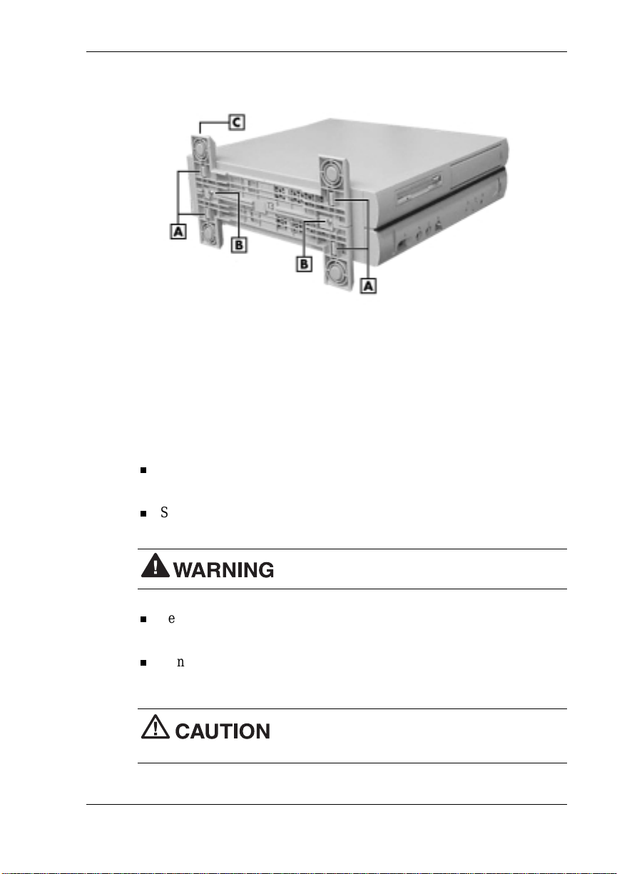
Attaching the slimtower stabilizer(s)
A
– Foot (4)
B
– Screw (2)
Cable Connections
After unpacking the system and positioning it in your work area, connect
the syst em componen ts using your Qui ck Setup poster and the following
tips.
Use the icons on the rear of t he system uni t to identify the keyboard,
mouse, printer, USB, LAN, power, audio, and monitor connectors.
See your network a dministrator for guid e lines on configuring the
system for LAN.
Set th e voltage switch correctly for your area. The cor rect setting for
the U.S. and Canada is 115V and 230V for Europe.
Connect system power cables to a surg e protector (recommended) or a
properly grounded wall outlet.
NECC recommends connecting the power ca ble
to a surge pr otector.
C
– Stabili zer (1 of 2)
Set the voltage switch correctly for your area.
Setting Up the System 2-3

Startup
Press the power button to start your s ystem. The power lamp lights green
to ind icate that th e system is on. The system perform s it s P ower-On SelfTest ( P OS T) and several messages app ear indicatin g th at the system is
checkin g its subsys tems.
Note
appears:
Uti l ity, im media tely press F2 while the startup screen displays. (See
Chapter 3, “Co nfigur ing the S ystem,” for information on using the BIOS
Setup.)
After a short delay, Wi ndows starts up.
If a problem occ urs, a s eries of be e ps might sound. If this happens
repeatedly after powering on, power off the system and turn to Chapter 5,
“Solving S ystem Problems.” The chapter provides helpful hints for
solving system problems.
Note
have changed, run the BIOS Setup Utility (see Chapter 3, “Config uring th e
System”).
On systems with Windows 2000, enter your password at the log-on box.
On systems with the Windows NT
Ctrl Alt Del
for entering a password.
Shutdown
At t he bott om of the NE C startup screen, the following message
<F2 for BIOS Setup>
If the system displays a message indicating that system settings
. If you want to enter the BIOS Setup
®
4.0 operating system, pr ess
when prompte d on-screen to do so. The log-on box appears
Follow t hese steps t o power off the system.
1.
If the system is in sleep mode (power lamp is amber), press a key or
move th e mouse to take it out of sl eep mode (see “Po w er Saving
Operation” in the next section ).
2.
Save and exit all your open applications .
3.
Make sure that the hard dr ive, diskett e dr ive, and any other drives are
not in us e. A lit device lamp indicat es that the device is in u s e.
2-4 Setting Up the System
Wait until all applications are saved and closed
before using the Windows shut down procedure in step 4.
Unless absolutely necessary, never power off the system if the system
power lamp is amber (sleep mode), if the ha rd drive lamp, diskette drive,
or other dev ice lamp is fla shing, or if any applicatio ns are open.
Information on the device might be lost or damaged.
4.
Click
Start
on the task bar, then point to and click
Selecting Shut Down gives you several choices in the pop-up
submen u. Select
Enter
for shut down.
If the system is configured with Windows 98 or Windows 2000,
Shut down the computer
the syst em shuts down a utomatically after a shor t in terval.
If th e s ystem is configured with Windows NT, and after you
perform a Windows shutdown, power off the system by pressing
and holding in the power button for four seconds or longer
before releasing.
5.
Turn off power to the monitor.
Power-Saving Operation
If the system is running Windows 98 or Windows 2000, you can put it in
sleep mode (a power-saving state) by pressing and immediately releasing
the power/sleep button on the front of the system unit. The sleep mod e is
a convenient way of conserving en ergy when you are g oing to be away
from the system for a short period of time.
Tak e care to press and immediately release the
power/sleep button to en ter the sleep mo de. Avoid pres sing and holding in
the power button longer than three seconds. If you do so, you might turn
off power and lose data from any open applications.
Shut Down
.
, then clic k OK or pr e s s
The syst em also goes int o sleep mode when it ha s been inacti ve, if the
power management has been enabled in BIOS, and an inactivity timeout
has been enabled. (See Chapter 3, “Configur i ng Your S ys tem” for
information on setting power management functions.)
Setting Up the System 2-5

When th e system goes int o sleep mode, it sa ves d ata and system s t atus
and then shuts off power to all possible components. Sleep mode lets you
save power without first s aving your work.
An amber power lamp indicates that the system is in sl eep mode. Press a
key or move the mouse to resume system operation where you left off.
System Care
Your system is a durable system built for heavy use. With protective
mea s ures and proper c a re, you can prevent pr oblems an d promote the
successful opera tion and long life span of the system .
Protecting Your System From Damage
There are s eve ral ways that you can protect your syste m from possibl e
damage. NECC strongly recommends the following protective measures.
Connect a surge sup pressor between your computer an d a grounded
wall outlet. A surge suppressor protects your system from sudden
transient increases and decreases in electrical power.
Be sure t o connect all per ipherals, su ch as a monitor an d printer, to the
surge suppressor . The surge prot e ctor sh ould be the only device th at
you plug into the wall outlet.
Avoid r ep eated power-on cycles. Th ese s u bj ect the system
components to temperature variations and stress.
Discon nect your system from teleph one and power lin es when an
electrical storm threaten s. If you h ave a fax/modem , lightning can
travel in on t he phon e l ine and da m age both the fax / modem and the
system u n it. Lightning can also travel in on power lines and damage
the mon itor and system unit.
Be sure that system power i s off befor e you connect or disconnect a
cable. Never make ca bl e changes when the system power is on. Doing
so can dam age the system an d its peripherals. However, n ot e that USB
devices do not require powering down the system to connect them.
Use BIOS Setup Utility options to protect against viruses (see
“Security Menu” in Chapter 3). Use appropriate virus detection
softwa re regularl y to protect the s ystem from computer viruses.
2-6 Setting Up the System

If you plan t o use soft ware pr ograms other than NECC-suppl ied
softwa re, NECC stron g ly recommends th at you take the necessary
steps, such as virus checks, to prot ect the system.
Position the system away from direct sunlight and extreme hot and
cold temperatures.
The recom mended oper ating envir onment is from 50°F to 95°F (10°C
to 35°C).
The recom mended non-operating en vironment ( shi pping or storag e) is
from 14°F to 158°F (-10°C to 70°C).
After turning off power, wait about five seconds for the hard drive to
spin down before you p ower on a gain.
Be sure th at nothing i s placed on top of th e system power cables .
Keeping Your System in Good Condition
Maintain the condition of your system by periodically using the following
procedures.
For safety, power off and unplug your system,
monitor, and any external devices before cleaning them.
Prevent dust from entering the system by covering it when it is not in
use.
Clean the outside of th e system with a soft cl ean cloth.
Remove stubborn st ains with a cloth s lightly damp en ed with a mild
detergent. Never u s e a strong cleaner or sol vent on any part of the
system.
Keep food an d liqui ds away fr om your system.
Peri odically clean the keyboard with a vacuum cleaner brush
atta ch ment. Do not use any liquid cleaners on the keyboa rd as they
can damage the keyboard.
If an object , such as a paper clip, falls in to the keyboard , tur n the
keyboard ov e r and gently sh a ke it.
Setting Up the System 2-7

Clean the monitor scr een wi th a glass clean er and wipe it with a clean,
lint- free cloth. Y ou can u s e wet/dry cleaning pads manu fa ctured for
monitor screens.
Moving or Shipping Your System
Use th es e s teps to prepar e your system for movi ng or shippin g.
1.
Back up the files on the hard drive to disk ettes, C D-ROM discs,
server hard drives, or other backup devices.
Take precautions for storing and transporting storage media so that
the media is not exposed t o m agnetic fiel d s or electrical impulses.
2.
Remove any disket te from the diske tte drive. If you have a disc in the
CD-ROM drive or DVD-ROM drive, rem ove the disc.
3.
Wake up a s ystem in sleep mode, s ave and close any open
appli cations, shu t d own Windows, and turn off the system and any
external option s con nected to it.
4.
Unplu g the system power cable from th e wal l outlet or sur ge
suppressor, then from the system itself.
5.
Unplug any ex terna l options from the wall ou tlets or surge
suppressor, then disconnect them from the system.
6.
If installed, remove the stabilizer(s) from the system.
7.
Pack the system compon ents in the ori ginal shippin g materials and
cartons. If these are not availa bl e, be su re to use adequ ate packing
materials to protect the components.
To set up the system, foll o w t he steps on the PowerMate ES SlimLine
Series Quick Setup poster that comes with the system.
2-8 Setting Up the System

More Information
Once you have your system up and running, we suggest you do the
following.
Install applications provided by NECC.
See “Setting Up a Healthy Work Environmen t ” in Appendix A.
Install any of your own applications. See the documentation that
comes with the application.
See th e following quick reference chart to find mor e in formation about
using the system.
Quick Reference to Information About Your System
Information Where to Find It
Accessing the world wide web Chapter 6
Adding system upgrades Chapter 4
Configuring your system Chapter 3
Setting up the system as a desktop Chapter 2
Setting up the system as a slimtower Chapter 2
Reinstalling the applications provided
by NECC
Installing the NEC INFO Center online
documentation
Pro tecti ng the system from viruses Chapter 1, C hapter 3
Setting a password Chapter 3
Setting up your system Chapter 2
Taking care of the system “System Care” in Chapter 2
Troubleshooting tips Chapter 5
Using support services Chapter 6
“NEC Application and Driver CD” in
Chapter 3
“NEC INFO Center” in Chapter 3
Setting Up the System 2-9

Configuring the System
Configuration Tools and Utilities
BIOS Setup Utility
FLASH Utility
NEC INFO Center
NEC Application and Driver CD
NEC OS Restore CD
System Board Jumper Settings
Intel Processor Serial Number Control Utility
3

This chapter provi des in formation on configuri ng your s ystem. The
chapter includes the following topics:
American Megatrends Inc. (AMI) BIOS Setup Utility for configuring
your system
FLASH Utility for BIOS updates
NEC IN FO Center for quick acces s to informa tion about your s yst em
NEC Applications and Driver CD for reinstalling the NEC-supplied
applications and installing optional drivers
NEC OS Restore CD for rest oring the operating system
jumper settings for setting various system configurations
Intel Processor Serial Number Control Utility for controlling the
reading of the proc essor s erial number.
See th e following tabl e for a quick gui d e to the utilities , tools, or
procedures required for configuring the system. For detailed information
about these and oth er tool s, see the sections following the table.
Configuration Tools and Utilities
The foll o wi ng table lis ts ways you can configure the system , and the
utility, tool, or procedure to use for the configuration.
Configuration Tools and Utilities
Configuration Method, Tool, or Utility
BIOS, updating FLASH Utility
Boot devices, determining BIOS Setup (Advanced Menu)
Boot order, changing BIOS Setup (Advanced Menu)
Clearing CMOS Jumper settings
Configuring jumpers on system board Jumper settings
Diskette drive, enabling BIOS Setup (Main Menu)
3-2 Configuring the System

Configuration Tools and Utilities
Configuration Method, Tool, or Utility
Drivers for NECC hardware, inst a lling NEC Application and Driver CD
Har d drive, setting a pre-dela y BIOS Setup (Advan ced Menu)
Inactivity timeout, setting BIOS Setup (Advanced Menu)
Keyboard options BIOS Setup (Advanced Menu)
NEC INFO Center, installing NEC Application and Driv er CD (s ee
“NEC IN F O Cente r”)
NEC INFO Center, uninstalling See “NEC INFO Center”
Operating system, restoring NEC OS Restore CD
Parallel port, enabling, configuring BIOS Setup (Advanced Menu)
Pas sword, setting or clea ring (user,
supervisor, or both)
Plug and Play, enabling BIOS Setup (Advanced Menu)
Power management, enabling,
configuring
Serial port, enabling BIOS Setup (Advanced Menu)
Software, reinstalling (NECC-provided) NEC A pplication a nd Driver CD
Sound, enabling BIOS Setup (Advanced Menu)
Time and date, setting BIOS Setup (Main Menu)
USB functions BIOS Setup (Advanced Menu)
Windows 98, Windows NT,
Windows 2000, restoring
BIOS Setup (Security Menu)
Jumper settings
BIOS Setup (Advanced Menu)
NEC OS Restore CD
Config ur in g t he Sy stem 3-3

BIOS Setup Utility
The AMI BIOS Setup Utility program lets you configure the main
components of your system.
Your system ships fr om th e factory with th e cor rect system parameter s for
your c onfigu rati on. Unless you ad d optional hardware, you do not n e e d to
run the BIOS Setup Utility to operate the system. However, you might
wish t o r un th e S etup Utility to set f eatures tha t customize the system,
such as secu rity featur es .
System configuration information is stored in nonvolatile memory. A
nonvolatile memory device retains its data when system power is turned
off. Nonvolatile memory in your system is stored in a complementary
metal-oxide semiconductor (CMOS) memory chip backed up by a battery
on the system board. The battery supplies continuous power to CMOS
memory and maintains configuration information when system power is
off (see “How to Replace the CMOS Battery” in Chapter 5).
NECC recommends that you print out or write down your current BIOS
Setup parameters and store the information in a safe place. This lets you
rest ore your system t o the current par am eters if you ever n eed to replace
the battery.
How to Start BIOS Setup
To start the BIOS Setup Utility, follow these steps.
1.
Turn on or re boot the s ystem.
2.
Press F2 as soon as you see the following message at the bottom of
the NE C startup screen.
<F2 for BIOS Setup>
You have about five seconds to press F2 before the system boot
continues.
Setup’s Main Menu appears.
3-4 Configuring the System

How to Use Setup
The Setup Utility has a Main Menu window and four top-level menus
with submenus. The menu bar at the top of the Main Menu window lists
the following top-level menus.
Main Use the Main M en u for basic system configuration. For
examp le, select Main to set the system d ate, set disk ette and hard dis k
parameters, or set the hard drive au to-detect feature.
Advanced Use the Ad vanced Menu to set up the system for
advan ced C M OS , advanced chi p s et , p ower management, Plug and
Play, serial and parallel peripherals, and hardware monitor.
Security Use this menu to set User and Supervisor Passwords and
keyboard wake-up password.
Exit Exits the Setup Utility with various save or discard options.
Use the keys listed in the legend bar on the bottom of the menu screen to
make the selections or exit the current menu. Help Setup information
dis plays on t he right s ide of th e menu screen.
The following table describes the legend keys.
Navigation Keys
Key Function
Esc Exits th e menu .
Enter Executes Command or brings up a
submenu.
F5 Loa ds the Default C onfig uration values for
this men u.
F6 Selects the Original Values for the field.
F10 Saves changes and Exits the BIOS Setup
Utility.
Up or down arrow keys Moves cursor up and down in the menu.
Left or right arrow keys Selects next menu.
Config ur in g t he Sy stem 3-5

To select one of the four men u s from the menu bar, use the left and ri gh t
arrow ke ys. Use the up or down ar row keys to select an item under the
menu.
Menu items preceded by a > contain a submenu of selecta ble fields for
setting system parameters. Display a submenu by using the up or down
arrow keys to move the cursor to the desired submenu, then press
Enter
An Item S p ecific Help window on the right si d e of ea ch menu displays
the help text for the cur rently select ed S etup option. It updates a s the
cursor moves to each new fiel d .
.
Pressing
describes the legend keys and their functions.
Press
The following subsections describe the four top level menus and their
submenus.
Main Menu
Choose t he Main Menu by selecting Main in the legend bar on th e M ain
Menu s cr een . Other Main Menu options are available by selecting
submenus.
Use th e arrow keys to select one of the Main Men u options and press
Enter
Explan ations of each Main Menu item are in the following table.
can cause your syste m to malfunction.
Note
system configurations. You should record your system’s BIOS settings and
save them in a safe place in t he event you need to restore or u pdate the
BIOS.
F1
on any menu brings up the General Help window that
Esc
to exit th e current window.
to select a submenu. Items with grayed-out text are not available.
Setting items on this menu to incorrect values
The following BIOS settings ar e typical and c an vary between
3-6 Configuring the System

Main Menu Item s
Menu Item Settings (default is bold)
System Date Set system date in this field. Press
to move between month, date, and year fields.
Example: 04/28/2000
System Time Set system time in this field. Press
to move between hour, minute, and second
fields.
Example: 09:30:50
Floppy Drive A Not Installed
360 KB 5 1/4"
1.2 MB 5 1/4"
720 KB 3 1/2"
1.44 MB 3 1/2"
2.88 MB 3 1/2"
Tab
Tab
or
or
Enter
Enter
Floppy Drive B
Not Installed
360 KB 5 1/4"
1.2 MB 5 1/4"
720 KB 3 1/2"
1.44 MB 3 1/2"
2.88 MB 3 1/2"
Config ur in g t he Sy stem 3-7

Main Menu Item s
Menu Item Settings (default is bold)
Primary IDE Master
Primary IDE Slave
Secondary IDE Master
Secondary IDE Slave
IDE Device
Configuration
Auto
Auto
Auto
Auto
Each device menu item displays the hard drive or
CD-ROM identifier if a device is installed.
If you inst all a hard driv e that does not feature
auto IDE type detection or your IDE hard drive
was formatted on another system with
paramet ers diff erent from those repor ted by t he
dri ve, enter a parameter for each of the fields in
the devic e submenu.
Bring up a device s ubmenu by pressing
The s ubmenus include IDE D evice Co nfiguratio n
and, depending on device selection, Fast
Programmed I/O Mode, 32 Bit Transfer Mode,
LBA Mode, and Block Mode. Each is briefly
des c rib ed in the following .
Auto
, User, CD-ROM, Floptical, Not Installed,
1-46
When set to Auto, the BIOS sets the correct
values fo r t he devi ce. Sel ecting U ser all ows you
to configure the BIOS for the device selected.
The Not Installed settin g indicates th at there is no
IDE device present in the system.
Enter
.
Depending on the option selected, one of the
fol lowin g submenus displays.
LBA Mode
On
, Off
When On is selected, it causes logical block
addressing to be used in place of cylinders,
heads, and sectors.
3-8 Configuring the System

Main Menu Item s
Menu Item Settings (default is bold)
Block Mode
Fast Programmed
I/O Modes
32 Bit Transfer Mode
Auto Detect Hard Drives Press
CPU Speed xxx MHz
Fro nt Side Bus Speed xxx MHz
Memory Size xx MHz
On
, Off
When On is selected, it allows block mode data
transfers.
Auto
, 0 -5
Use these settings to configure the Advanced
PIO Mode.
On
, Off
When On, allows 32 bit IDE data transfers.
Should only be On if supported by a chipset
controller.
Enter
Auto detects all hard drive parameters.
Not selectable, displays information only.
Not selectable, displays information only.
Not selectable, displays information only.
BIOS Version A6303P2 V1.0
Not selectable, displays information only.
Config ur in g t he Sy stem 3-9

Advanced Menu
Choose t he Advanced Menu by selecting Advanced in the legend bar on
the Main Menu screen. Ad va nced Menu opti ons include:
Advanced CMOS Setup
Advanced Chipset Setup
Power Management Setup
Plug and Play Setup
Peripheral Set up
Hardware Monitor Setup.
Use th e arrow keys to select an Advanced Menu option. Pr es s
display the submenu . Items with grayed-out text are not available.
Explan ations of each A d vanced Menu opti on are in the following tables.
Setting items on this menu to incorrect values
can cause your syste m to malfunction.
Advanced Menu - Advanced CMOS Setup
Menu Item Settings (default is bold)
View DMI Event Log Status onl y. Pres s
Clear all DMI Events
No
, Yes
Logs
Selectin g No prevents cl earin g out the D M I events
logs.
Event Logging
Enabled
, Di sabled
Selectin g Enabled permi ts event loggi ng.
Mark DMI Events as
Press
Enter
Read
Press Enter to mark DMI event log as read.
Enter
(Yes/No)
to view .
Enter
to
3-10 Configuring the System

Advanced Menu - Advanced CMOS Setup
Menu Item Settings (default is bold)
Quick Boot
Delay for Hard Drive
(seconds)
1st Boot Device
2nd Boot Device
3rd Boot Device
Try Other Boot Devices
Enabled
When Enabled, the BIOS does not test system
memory above 1 MB or wait for ready signals, allowing
a quick boot.
3,
Selects the amount of time for hard drive delay.
Floppy
LS-120/Zip, ATAPI Zip, CDROM, SCSI, Network
Sets the diskette drive as the first boot device.
IDE-0
Sets the second boot device.
CD-ROM
Sets the third boot device.
Yes
Select Yes to cause the system to try to boot from
other boot devices if there is a boot failure. Selecting
No causes the boot to be carried out from selected
devices.
, Di sabled
Disabled
, No
, 1 -10
, Disabled, IDE-0, IDE-1, IDE-2, IDE-3,
Floppy Access Control
S.M.A.R.T. for Hard
Disks
Read-write
Select Read-write to allow the diskette drive to have
read-wri te capa bilities.
Disabled
Select Enabled t o use the Self Monitoring Analysis and
Reporting Technology (S.M.A.R.T.) for reporting a
possible problem with an IDE device. After receiving
the warni ng, the BIOS aler ts you to the pr oblem.
, Read-only
, Enabled
Configuring the System 3-11

Advanced Menu - Advanced CMOS Setup
Menu Item Settings (default is bold)
Boot-up Num-Lock
Pas sword C heck
Boot to OS/2>6 4 M B
CPU Serial Number Disabled,
System BIOS
Cacheable
On
, Off
Select Off to lock the numeric keypad on boot up.
Setup
, Always
Allows th e user to d etermine at wh at moment a
password check is needed.
No
, Yes
Select Yes to enable a boot to OS/2 if RAM is greater
than 64 MB.
Enabled
Control s detect ion of t he processor s er ial number.
Disabled,
Select Enabled to allow storing of system BIOS in
RAM.
Enabled
Advanced Menu - Advanced Chipset Setup
Menu Item Settings (default is bold)
USB Function Enabled,
Select Enabled t o enable use of USB functions for
USB devices.
USB Keyboard Legacy
Support
Enabled,
Select Enabled to enable the legacy keyboard
functions.
3-12 Configuring the System
Disabled
Disabled

Advanced Menu - Advanced Chipset Setup
Menu Item Settings (default is bold)
Memory H ole En a b led,
Select Enabled t o reserv e a space in the memory,
between 15 and 16 MB, for certain ISA boards.
ClkGen Spread
Spectrum
Enabled
Select Enabled to enable the Clock Generator
Spec trum and limit the ri sk of electromagnetic
emissions.
Disabled
, Di sabled
Advanced Menu - Power Management Setup
Menu Item Settings (default is bold)
ACPI Standby State
USB Keyboard Wakeup
From S3
Power
Management/APM
S1
, S3
Select S1 for a low wake-up latency sleeping state. In
the S2 mode, the CPU, cache, and chipset contexts
are lost.
Disabled
Select Enabled to allow the system to wake up from a
keyboard input.
Enabled
Select Enabled t o enable Power Management and
Advanced Power Management (APM).
, Enabled
, Di sabled
Gr een PC LED Status
Video Power Down
Mode
Dual Color
Select Dual-Color to show a green LED for normal use
and an orange LED for standby use.
Standby
Select St andby or Suspen d to power down th e video
display as a power saving feature.
, Single Color, Blinking
, Di sabled, Suspend
Configuring the System 3-13

Advanced Menu - Power Management Setup
Menu Item Settings (default is bold)
Hard Disk Power Down
Mode
Standby Time Out
(Minutes)
Suspend Time Out
(Minutes)
Power Button Function
Restore on AC/Power
Loss
Suspend
Select Suspend or Standby to power down the hard
disk as a power saving feature.
Disabled
Specifies the length of time of system inactivity while in
ful l power on state b efore en tering Stand by stat e.
Disabled
Specifies the length of time of system inactivity while in
Standby st ate befo re entering Su spend po wer state.
Suspend
Suspend sets the power switch for Suspend (Sleep)
mode. Wit h power on , pressing the switch o nce pla ces
the system in sleep mode. Pressing and holding the
switch in for 4 seconds turns power off.
Last State
The Power On setting automatically turns power on
after a power loss. The Power Off setting requires the
user to restart the system with the power button. The
Las t State s ettin g restores the system to the state
where it was on power loss.
, Standby, Disabled
, 1, 2, 4, 8, 10, 20, 30, 40, 50, 60
, 1, 2, 4, 8, 10, 20, 30, 40, 50, 60
, On/Off
, Power Off, Power On
Resume on Ring Enabled,
Enabled allows the system to boot up on an incoming
telephone call. Disabled causes the system to ignore
any incoming call from a modem.
Resume on LAN
Enabled
Enabled allows the system to boot up on an incoming
LAN signal . Disabled causes the s ystem to ignore a ny
incoming signal from LAN.
3-14 Configuring the System
Disabled
, Di sabled

Advanced Menu - Power Management Setup
Menu Item Settings (default is bold)
PME Function
Resume on RTC Alarm
RTC Alarm Date
RTC Alarm Hour
RTC Alarm Minute
RTC Alarm Second
Enabled
Select Enabled to allow the system to react to PCI
Power Management Enabled wake up events.
Disabled
When Enabled, you can choose the time the system
boots up (see the following time settings).
15
Sets the day that the sys tem boo ts u p (when Resume
on RTC Alarm is Enabled).
12
Sets real time clock alarm hour (when Resume on
RTC Alarm is Enabled).
30
Sets real time clock alarm minute (when Resume on
RTC Alarm is Enabled).
30
Sets real time clock alarm second (when Resume on
RTC Alarm is Enabled).
, Di sabled
, Enabled
, Every Date
, 1-00
, 0-59
, 0-59
Configuring the System 3-15

Advanced Menu - Plug and Play Setup
Menu Item Settings (default is bold)
Plug and Play Aware
O/S
Clear NVRam
Primary Graphics
Adapter
PCI VGA Palette Snoop
DMA Channel
0, 1, 3, 5, 6, 7
IRQ 3, 4, 5, ,7, 9, 10,
11, 14, 15
Yes
No,
Select No to allow the BIOS to initialize any add-on
boards (Windows NT only). Select Yes to allow the
operating system to initialize any add-on boards
(Windows 98 and Windows 2000).
No
, Yes
Select No to prohibit clearing of NV Ram.
Add-on VGA
Select Onboard VGA if VGA is integrated on the
system board.
Disabled
Set to Enabled to enable PCI VGA palette snooping.
PnP
, ISA
Permits configu r ing th e DMA chan nels either by Plug
and Play or by ISA.
PCI/PnP
Permits configu r ing th e interrupt requests either by
PCI /Plug a nd Play or by ISA.
, Onboa r d VGA
, Enabled
, ISA
Reserved Memory Size
Reserved Memory
Address
Disabled
Select Enabled t o reserv e a non-w r iteable zone i n
memory.
D0000
Defines the non-writeable zone in memory.
3-16 Configuring the System
, Enabled

Advanced Menu - Peripheral Setup
Menu Item Settings (default is bold)
Onboard AC ’97 Audio
Onboard AC ’97 Modem Enabled,
Onboard LAN
Onboard Serial Port A
Onboard Serial Port B 3F8/COM1, Auto,
Serial Port B Mode
IR D uplex Mod e
Enabled,
The Enabl ed setting allows use o f onboard sound .
Onboard mo dem not a vailable.
Enabled
Select Enabled t o allow u se of onboard local ar ea
network.
3F8/COM1
2E8/COM4
Defines serial port A base I/O address.
2E8/COM4
Defines serial port B base I/O address.
Normal
Select Normal to set the port for normal use.
Half Duplex
This option allo ws the In f ra red Duplex mo de to
function in one di recti on at a time (Half D uplex) o r both
directions (Full Duplex).
Disabled,
Disabled
, Di sabled
, Auto, Disabled, 2F8/COM2, 3E8/COM3,
, 1.6us, 3/16 baud, ASKIR
, Ful l Duplex
Disabled
, 2F8/COM2, 3E8/COM3,
Onboard Parallel Port
Parallel Port Mode
378
, Auto, Disabled, 278, 3BC
Select Auto to allow the BIOS to automatically assign
the parallel port to an available parallel port IRQ.
ECP
, Normal, Bi-Directional, EPP
Use this mo d e to choo s e the operating mode of the
onboard parallel port.
Configuring the System 3-17

Advanced Menu - Peripheral Setup
Menu Item Settings (default is bold)
EPP Version
Parallel Port IRQ
Parallel Port DMA
Channel
Keyboard/Mouse Power
On Function
N/A
, 1.9, 1.7
Use this setting (1.7 or 1.9) to select the EPP version.
7
, 5
Allows setting of the interrupt request (IRQ) for the
parallel port.
3
0, 1,
Allows you to choose a DMA channel for the onboard
parallel port in ECP mode. Displays only when parallel
port is enabled and in ECP mode.
Disabled
Right
This option, when enabled, allows system to be turned
on b y pressing a spec ific key or mov ing the mouse.
, Pow erkey, Specif ic Key, M ouse Lef t, Mouse
Advanced Menu - Hardware Monitor Setup
Menu Item Settings (default is bold)
ACPI Shut Down
Temperature
°
C/176°F
80
ACPI gives the operating system direct control over
the power management and Plug and Play functions of
a computer . The system shuts down at the
tem perat ure indicated .
Chassis Intrusion
Temperat ure, Fan
Speeds, Voltages
Disabled
When Enabled, the chassis cover must be in place
before the system can start up. When Disabled, the
system can be started without the cover in place.
Not selectable, information only.
3-18 Configuring the System
, Enabled

Security Menu
Choose the Security Menu by selecting Security in the legend bar on the
Main Menu screen. Other Security Menu options are ava ilable by
selecting submenus.
Use th e arrow keys to select one of the Secur ity Menu opti on s and press
Enter
to select a submenu. Items with grayed-out text are not available.
Explanations of each Security Menu item are in the following table.
Security M en u It ems
Menu Item Settings (default is bold)
Set Supervisor
Password
Set User Password [Enter]
Set Keyboard Wake Up
Password Change
[Enter]
Use this field to set or change the supervisor
password. Press
the passw ord can be entered and con f irmed.
Use this field to set or change the user password.
Press
pas sword ca n be entered and confirmed.
[Enter]
Use this field to change the keyboard wa keup
password.
Enter
to bring up a dialog b ox where
Enter
to bring up a di alog box where the
Configuring the System 3-19

Exit Menu
Choose t he Exit Menu by selecting Exit in the legend bar on the Main
Menu. Other Exit Menu options are available by selecting submenus.
Use th e arrow keys to select one of the Exit M en u options and pr es s
to disp lay the submenu . Ex p lanations of each Exit Menu item are in the
following table.
Exit Menu Items
Menu Item Settings (default is bold)
Exit Saving Changes Implements the changes just made, and exits BIOS.
Exit Discarding
Changes
Load Optimal Settings Reverts to the factory set optimal settings.
Load Fail Safe Settings Reverts to the factory set fail safe settings.
Load Original Valu es Re verts to the fa ctory- shipp ed sett in g s.
Reverts to the settings from before the BIOS session.
FLASH Utility
The system BIOS resid es on a flash read only memor y (ROM) chi p in
your system. The FLASH ROM can be updated using the following
procedu re. Before starting the BI OS u p date, we recommend that you fir st
contact NECC for ass istance (see Ch apter 6 for conta ct information).
Update the FLASH ROM with a BIOS flash diskette. The diskette
contains the latest version of th e BIO S code. You can get the diskette
from NECC or download the BIO S from the NECC webs ite. S ee
Chapter 6 for download and website information.
Enter
Update the BIOS from the BIOS flash diskette as follows.
1.
Write down the BIOS Setup parameters currently set on your system.
2.
Turn off t he system.
3.
Put the flash diskette in the diskette drive, and turn on the system.
3-20 Configuring the System

4.
When th e fl ash upgrade m en u ap p ears, choose
Memory Area from a file
5.
When the menu asks you to enter a path/filename, use the arrow keys
to select the “.bio” file a nd pres s
6.
The utility asks for confirmation to load the new flash into memory.
Continue with Programming
Select
7.
After the upgrade completes, remove the diskette.
8.
Reboot the system and s tar t the Setup program. Press F5 to reset the
BIOS defaults. Use the recorded Setup selections you made at the
beginning of this procedure to set the parameters.
NEC INFO Center
The online NEC INFO C enter pr ovides qu ick acc ess to in format ion about
your s ystem. The NEC INF O Center includ es the followin g modules:
Tour
Use Tour to find information about easy-to-use NECC printed and
online documentation, software installation tools, and many support
services.
User’s Guide
Use this module to get quick access to basic information about your
system.
Update Flash
.
Enter
.
.
Questions
Look in this module to get answers to frequently asked questions
about you r syst em .
Solutions
Go to this module to find solutions to common system problems.
Services
Check th is module for a qui ck reference t o th e many NECC suppor t
services available to you.
To install the NEC INFO Center, double click the NEC OnLine Docs icon
on th e Win d ows des k top. Once the NEC INFO Cent er i s in s talled, an
NEC INFO Center icon appears on the Windows desktop. Double click
on thi s icon to start the NEC INFO Center. Th e INF O C enter openin g
screen appears (see the followin g figure).
Configuring the System 3-21

Click on an NEC INFO Center module of your choice, depending on the
information you want to see. We suggest you start with the Tour module.
NEC INFO Center opening screen
To uninstall the NEC INFO Center, use these steps:
1.
Access the C:\NEC INFO direc tory on your system.
2.
Double click the
Unwise.exe
NEC INFO Center and the
Alter n ately, you can cl ick
Panel
. At the Control Panel, double click
Double click
NEC INFO Center
To reinstall the NEC I N FO C enter, use the NEC A p pl ication and Driver
CD (see the followin g section, “NEC Application and Driver CD”).
3-22 Configuring the System
icon to remove all files related to the
C:\NEC INFO
Start
, point t o
direct ory.
Settings
Add/Remove Programs
, and click
and follow the prompts.
Control
.

NEC Application and Driver CD
Use the NEC Application and Driver CD to reinstall NECC-provided
softwa re, including
applications
utilities and device drivers
the NE C IN F O Cen ter (onlin e documentation).
You can also use the NEC Application and Driver CD at any time to
restore an application, driver, or utility.
Note
CD, t he full r estor e process loads al l the fa ctory-insta lled softwar e that
came with your system.
If you perform a full system restore usi ng the NE C OS Restore
If you add NEC C ha rdware options specified for your s ystem, you c an us e
the NEC Application and Driver CD to install the drivers for the options.
Install the software from the NEC Application and Driver CD as follows.
1.
Power on your system .
2.
Insert the auto-start Application and Driver CD into the CD-ROM
drive. The Selecti ve Restore screen appears, prompting you to sel ect
an application or driver from the list.
3.
Click on an application, driver, or utility in the
“Applications/Drivers:” windo w.
4.
Read th e information g iven in the “Important Setup Information:”
window.
5.
Click
Install
to install your selection. Follow any on-screen
instructions to install your selection.
6.
7.
Exit
Click
to close th e A p pl ication and Driver program.
Remove t he CD from the CD- ROM drive when the installation is
complete.
Configuring the System 3-23

NEC OS Restore CD
Use t he NEC OS Re s tore CD to restore your system to its origina l factor y
stat e if a problem occur s th at causes data loss or corruption. The NEC OS
Restore CD provide s options for a fu ll system restore with factoryinst alled softwar e or for a restore wi th only the oper ating system and
drivers. A full rest ore loads all the factory-installed software.
If you select to restore only the operating system and drivers, you can use
the NE C Ap pl ication and Driver CD to select the software you want to
load on your system. See the previous section, “NEC Application and
Driver CD,” for information on using the Application and Driver CD.
Before s t arting, we recommend that you first contact NECC for assi stance
(see Ch apter 6 for contact information).
Use t he foll owing steps to pe rform the OS Rest ore with the boot able
Master Restore disk ette and the OS Restore CD.
The NEC OS Restore program deletes all the
data on your hard drive. If possible, back up your data before performing
an OS restore.
1.
If possible, back up all your critical data files onto storage media
(such as diskettes, Zip disks, or CD-ROM discs) or to an external
storage device such as a ser ver hard drive.
2.
Remove any disket te or CD- RO M disc fr om your s ystem.
3.
Power down your syst em. In s ert the bootable Master Restore disk e t te
into the diskett e drive and the NEC OS Rest ore CD into th e
CD-ROM dr ive. Power on the system.
The syst em boots and th e NE C Computers Inc. Rest ore screen
appears.
4.
At th e Restore screen, cl ick Y to continue (or N to exit the program).
A warning screen appears, with a prom p t th at continuing the restor e
will destroy all data on your primary drive.
3-24 Configuring the System

5.
At th e warn ing screen, click C to continue (or X to exit the program).
A restore selection s cr een appears, with a prompt askin g if you wa nt
a full r estore or an opera ting system an d driver restor e.
6.
At th e restore selection screen, click F for fu l l restore or O for an
X
opera ting system and driver restore. (Or click
to exit the program.)
A seri es of restoring screens appear, advising you th at the restor e
process is contin uin g. The rest or e process takes a few minut es t o do.
7.
At the completion of the restore, a Restore Complete screen is
displayed, with a prompt to either do system updates (see step 8) or
reboot the system (see st ep 9).
8.
If you are updating your system, do the following procedure at the
system update prompt.
Remove the Master Restore bootabl e diskette and restor e CD
from their drives.
Insert the NEC Application and Driver CD or other CD into the
drive(s).
If you are using the NEC Application and Driver CD, go to
“NEC Application and Driver CD” earlier in this chapter to
complete the update.
9.
If you a re not updating your s ystem, r e move the M aster Res tore
bootable d iskette and restore CD fr om th eir drives. Pr es s any key to
reboot your system and open the Win dows desktop.
System Board Jumper Settings
Syste m board jumpers enable you to configu re your system for a
particular system requirement. Conditions that might require changing
jumper settings include the following situations.
You a re adding a sound board to your system.
You need to restore the C M OS settings to th e fact ory state.
Your BIO S is corrupted an d you need to recover the BIOS.
Before s t arting, we recommend that you first contact NECC for assi stance
(see Ch apter 6 for contact information).
Use th e fol lowing figure to locate th e ju mp ers on the system board.
Configuring the System 3-25

Locating the system board jumpers
A
– Keyboard Wakeup (JKBV1)
B
– Onbo ard Audio (JP3)
C
– BIOS Recovery (J4)
Jumpers are set correctly at the factory for your
con figur ation. Only change the appropriate jumper setting for your
app l icati on. Otherwis e, keep the jumpers at t heir factory setting s .
D
– CPU Type (J23)
E
– Save to RAM (JP4)
F
– CMOS Clear (JBAT1)
Set the jumpers as follows.
1.
Power off and unplug the s ystem and any external option s. Remove
the syst em cover (see “Removing the Cover”).
2.
Locate the appropriate jumper bl ock on the system board (see the
previous figure “Locat ing the system boa rd jumpers ”).
3-26 Configuring the System

3.
Move the appropriate jumpers for your application as shown on the
following figure, “Setting system board jumpers.”
Note
NECC for ass istance (see Chapter 6 for contact information).
a jumper setting.
4.
Befo re setting jumpers , we recommend th at you f ir s t contac t
The system power must be off before changing
Check your setting s to be su re that they ar e cor rect for your
application.
5.
Replace t he system cover (see “Replacing t he Cover”). Connect
system p o wer cables and ex ternal options.
6.
Power on the system and launch the BIOS Setup Utility before POST
and r ecu s tomize your BIOS s ettings as necess ary.
Configuring the System 3-27

Setting system board jumpers
3-28 Configuring the System

Intel Processor Serial Number Control Utility
The Intel Processor Serial Number Control Utility is a Windows program
that enables or disa bl es the reading of the Pentium II I processor serial
number by software. This function lets you control which software
pr ograms or we bs ites have per missi on to rea d t he processor serial
number. When installed, the utility runs automatically each time the
system p o wers on.
This utility places an icon in the Wind ows system tray. The icon provides
a visual status of the processor serial n umber. Y ou have the opti on of
hidin g th e s ystem tray icon. You can enable or disable the processor serial
number at any time. However, enabling the serial number requires
restarting the system.
The following information describes:
system requirements
installation procedures
processor serial number features
FAQs
technical suppor t.
System Requirements
The Intel Processor Serial Number Control Utility requires:
a Pentium III processor-based s ystem
Windows 98, Windows NT 4.0 (or later), or Windows 2000
2 megabytes of hard drive space.
Installation
The Intel Processor Serial Number Control Utility (version 1.0) comes
already install ed on your system. Th e s ystem ships with the processor
serial number turned off.
Configuring the System 3-29

Processor Serial Number
The Int el processor s er ial number, a fea ture of the Pent ium III processor,
is an iden tifier for the processor. Th e processor ser i al number is uni qu e,
and when u s ed in conjunction wi th ot her identification methods, can be
used to i d entify the system or user. This n um ber can be used in a wide
variety of applications which benefit from stronger forms of system and
user iden tification.
The pr ocessor serial n umber is analogous to a conventi on al serial number,
with these importan t differen ces :
A software applicat ion can read th e processor serial number.
You can enable or disable the reading of the serial number via utility
progr ams such as this on e, or vi a the BIOS, depending on the system
configuration.
For additional informa tion about the Pentium III processor and the
processor serial nu m ber , visit
Frequently Asked Questions
What are the benefits of the pro cessor serial number?
You can use the processor serial number in applications which benefit
from stronger forms of system and user identification.
www.intel.com/pentiumiii
.
Why would I want to turn off my processor seri al n umb er?
Intel believes the processor serial number can provide compelling benefits
to user s . They are developing features in conjun ction with the processor
ser ial num be r to allow responsibl e s e rvice providers to provide services
whi c h maint a in your pr ivacy. H owever, if you a re concerned that a given
application/service using your processor number might impact your
privacy, you can turn off the processor serial number using the utility.
What is the default stat e of the pro cessor serial number?
The defa u lt state of th e pr ocessor serial number is on, un ti l the Processor
Serial Number Control Utility is installed. Once the Processor Serial
Number Control Utility is installed, it turns the processor serial number
off by defau lt. You can u s e th e u tility to turn on the processor serial
number.
3-30 Configuring the System

Can a website read my serial number without my knowledge?
No, generally not. Websites cannot read serial numbers unless you allow
them to d own load a program which can read th e pr ocessor seria l n umber.
Almost all browsers ar e configured to warn users wh en ever they
downl oad executabl e s oftware. Unl ess you d isable the warning in the
browser , you should recei ve a notifica tion.
Does Intel track serial numbers?
Generally not, other than related to the manufacturing process. Intel does
not, in th e absences of advance and expres s consent of a user, collect
serial number data which is otherwise identified with a user.
Which programs and/or websites currently use the processor
serial number?
You can find a complete list of programs which can take advantage of the
processor serial nu mber and other n ew capabiliti es of the Pentium III
processor at
http://www.intel.com/pentiumiii/utility.htm
.
How can I tell if my processor serial number is turned on?
The vast majority of Penti um III processor-based systems ship with the
processor serial nu mber enabled. Th e control utili ty allows you to ch eck
the st atus by:
Viewin g the icon itsel f. The disabled icon shows a red cir cle with a
white “x.”
Click ing the task tray icon and selecting the “Status” menu item. Or
you can select the menu from the tool tip shown when you position the
mouse over the task tray icon.
Technical Support
For world wide 7 days a week, 24 hours a day technical support, please
visit the Intel support website at
support@intel.com
Email:
In th e United States, call
Pacifi c Standard Tim e.
For world wide phone contacts, please see
http://support.intel.com/support/feedback.htm
http://support.intel.com
.
800-628-8686
from 5:00 a.m . to 5:00 p. m .
Configuring the System 3-31
.
.

Installing System Upgrades
General Rules
Safety Precautions
System Cover
System Board Upgrades
Expansion Boards
Data Storage Devices
4

This chapter provides installation instructions for a variety of industrystandard and NECC upgrades t hat you ca n add to your syst em.
Included in the chapter are procedures for
memory module upgrade
processor upgrade
expansion board installation
data s torage device installation.
Most procedures req u ire the removal of the system cover . Procedures for
removi ng the cover are included in th is chapter.
General Ru le s
Follow these general rules when installing system upgrades.
Turn off system power and unplug the power cable.
Turn off an d disconnect all peripherals from the front and rear of the
system.
When handling boards or chips, touch the system metal frame to
discharge static.
Do not di sassemble parts other than those specified in the procedure.
All screws are Phillips-head unless otherwise specified.
Label any cable conn ectors before d i s con necting. Note where the
connector goes and in what position it was installed.
Safety Precautions
Obser ve safety rules when working inside the system and when hand ling
comput er components. Avoid electric shock or p er s onal injury by
observing the following warning.
Before removing the system cover, turn off the
power and unplug the system power cable. Power is removed only when
the power cable is unplugged.
4-2 Installing System Upgrades

Stati c electricity and improper installation procedures can damag e s ystem
components. Protect system compon ents by following these sa fet y
instructions.
Electros tatic dischar ge can damage sy stem
components. Dis charge static electr icity by touching a metal object bef ore
removing the system cover.
Avoid carpets in cool, dry areas. Leave boards and chips in their
anti-static packaging until ready to be installed.
Dissi p ate static el ectricity before handling an y system components
(boards, chips, memory modules) by touching a grounded metal
object, such as the system’s unpa in ted metal cha s sis.
If possi ble, use antistatic devices, such as wri s t straps and floor mats.
Always hold a chip or board by its edges. Avoid touching the
components on the chip or boa rd.
Take care when connect ing or disconnecting cabl es . A damaged cable
can cause a short in the electrical circuit.
When in stalling a cabl e, route the cabl e s o i t is not pinched by other
components and is out of t he path of the system cover.
Preven t damage to the con nectors by ali gning connector pins before
you connect the cable.
Misaligned conn ect or pins can cause d amage to system com p onents at
power-on.
When di scon necting a cable, always pul l on the cable connector or
strain-relief loop, not on the cable itself.
System Cover
You need to remove the system cover to access the interior for instal ling
system upgrades.
The following sections describe how to remove and replace the system
cover.
Installing System Upgrades 4-3

Removing the Cover
Remove the cover as follows.
power and unplug the system power cable. Power is removed only when
the power cable is unplugged.
1.
Turn off th e s ystem an d a ny peripherals and un plug th e system pow e r
cord.
2.
Disconnect any external options ( such as a keyboard, mouse, and
monit or) from the fr ont or r ear of the system.
If th e mous e and keyboard cables are installed in the anti-theft
brack et, remove the screw fastenin g the bracket t o th e ch assis and
release the cables. The screw is access ible from in s i de the chassis ,
after the cover is removed.
3.
If the system is configured as a slimtower, remove the stabilizer(s).
Position the system unit on its side on a table, with the stabilizers
over the edge of the tabl e.
Remove t he screws atta ch ing the stabi lizers to the chassis and
remove the stabilizers (see Chapter 2 for screw locations).
Befo re removin g th e cove r, turn off sy stem
4.
If you have a padlock in the anti-the ft ring on the rear of the s ystem,
remove it.
5.
Remove t he screw and anti-theft rin g secu ring the cover to the rear of
the system.
Removing the cover screw
A
– Cover Screw
4-4 Installing System Upgrades
B
– Cover

6.
Pre s s in on the sides of the cover and slide th e cove r about one inch
towards the front of the chassi s.
Note
cover unit includes the top panel, left and right side panels, and front
panel. Do not attempt to separate the panels from the cover unit.
7.
The c over is a one piece unit that fits tightly to the chassis. The
Lift the cover off the system and set as ide.
Replacing the Cover
Remo ving the cover
A
– Cover
Replace t he cover as foll ows.
Ens ure tha t all cables are positioned to prevent
crimping, abras ion, or cutting while installing the cover. Check that the
ribbon cables are folded along their fold lines and out of the direct path of
the cover.
1.
If rem oved, reinstall the mouse an d keyboard anti - theft bracket, with
the mou se and keyboard cables insid e the bracket.
2.
Position the cover over the chassis so that the front edge of the cover
is about on e inch beyond the front ed ge of the ch assis (see the
preced ing figur e).
Installing System Upgrades 4-5

3.
Align the tabs on the sides of the cover with t he corre s ponding slot s
on the bottom edges of the chassis si des.
4.
Firm ly press the cover ag ainst the chassis and slid e the cover towar d s
the back of the chassi s unt il it locks in place.
Note
check that the cover tabs on the sides of the cover are properly inserted
into their slots in the chassis. Also check that the tab on the riser board is
positioned inside the chassis (see “Installing an Expansion Board” later in
this chapter for tab location).
5.
If the cover does not slide all the way to the rear of the chassis,
Secure the cover with the previously removed cover screw and antitheft r ing.
6.
If you have a padlock for the anti-theft ring on the rear of th e chassi s ,
inst all it.
7.
If you are using the system as a slimtower, reinstall the stabilizers.
8.
Reconnect all exter nal peripher als.
9.
Plug in your power cables.
System Board Upgrades
This section describes how to install upgrades on the system board.
Procedures described in this section include:
adding memory modules
upgradin g t he processor.
The following figure shows the locations of the memory module sockets
and th e processor socket on the system boa rd.
4-6 Installing System Upgrades

Locating the memory module and processor sockets
A
– Memory Sockets 1 and 2
B
– Processor Socket
Memory Upgrade
Memory upgrades are installed into two memory module sockets on the
system board. The sockets support up to 512 MB of high-speed memory.
The system supports 168-pin, 100-MHz non-ECC SDRAM modules in
64-, 128-, and 256-MB unbuffered memory configurations.
Use the following guidelines in selecting DIMM types:
memory can be installed in one or two sockets
the si ze of the DIMMs can var y betw een sockets
the speed of t he DIMMs must match or exceed the processor bus
speed
single- and double-sided DIMMs are supported.
To deter mine what configuration of DI MM s to use, see the table
“Supported DIMMs.”
For sample memory configurations, see the table “Sample DIMM
Upgrade Paths.”
C
– Fan C onnector (und er CD-ROM drive)
Installing System Upgrades 4-7

To locat e memory module s ockets on the system board, see the previous
figure, “System board sockets and connector s .”
To determine the memory you need to purchase for a memory upgrade,
see “Ch eck ing System Mem ory.”
Supported DIMMs
DIMM Size Configuratio n
64 MB 8 Mbit x 72
128 MB 16 Mbit x 72
256 MB 32 Mbit x 72
Sample DIMM Upgrade Paths*
Total Memory DIMM 1 DIMM 2
64 MB 64 MB 128 MB 64 MB 64 MB
128 MB 128 MB 256 MB 128 MB 128 MB
256 MB 256 MB 512 MB 256 MB 256 MB
*The information in this table shows sample DIMM upgrade paths. It does not
represent every combination of DIMMs supported in the system.
Checking System Memory
If you do not know how much memory is installed in your system, check
the amou n t by using the following proced u re.
1.
On the Windows desktop, point to
mouse button.
4-8 Installing System Upgrades
My Computer
, an d click the right

2.
With the left mouse button, click
Properties
. The
General
tab shows
the ran d om a ccess memory (RAM). This is th e amount of system
memory in your computer.
In Windows 98 or Windows 2000, you can also find the amount of
memory by pointing to
and selecting th e
Performance
My Computer
, clicking the right mouse button,
tab.
Note
the Power-On Self-Test or in Win dows with the am ount of memory that
you installed, check that you instal le d the memor y modu le s correct ly .
If you fin d a discrepancy in the amount of memory displa yed at
Removing a DIMM
If your memory configuration requires the removal of a DIMM module,
use the fol lowing step s .
boards or memory modules, reduce static discharge by touching the
chassis.
1.
Remove t he cover (see “Removin g t he Cover” earlier in th is chapter).
2.
Locate the memory upgrade sockets on the system board (see the
figure “Locatin g th e memory module and processor sock ets” earlier
in this chapter).
3.
Eject a DIMM by pressing th e pl astic clip s at th e ou ter edges of th e
socket away from the memory module (s ee the following figure).
Before opening the system and before handling
Installing System Upgrades 4-9

4.
If you ar e installing a D I M M, see “Installing a DIMM” in the next
section.
5.
If you ar e n ot installing a DIMM, repla ce th e cover (see “Replacing
the Cover” earlier in this chapter) .
Installing a DIMM
Use the following steps to install a memory module.
Removing a DIMM
A
– Plastic Clip s
1.
Remove t he cover (see “Removin g t he Cover” earlier in th is chapter).
2.
If you need to remove a curr en tly install ed DIMM, see “Removing a
DIMM” earlier i n t his chapter .
Before you install a DIMM, reduce static
discharge by touching the chassis.
3.
Align the notches on the new DIMM with the keys in an empty
memor y sock et (see the following figure).
4.
Press the DIMM firmly into the socket.
5.
Ensure that the locking clip at each end of the DIMM cli ck s closed.
4-10 Installing System Upgrades

Install ing a DIM M
A
– Plastic Clip s
6.
Replace t he cover (see “Replaci ng the Cove r” earlier in this chapter).
Processor Upgrade
The system board has a Socket 370 for mounting a Celeron processor or a
Pent iu m III processor .
To remove the processor from the Socket 370, see “Removing the
Processor” in the following sections. To instal l the upgrade processor, see
“Insta lling an Upgra de Processor” in the follow ing se ctions.
service center for assistance in upgrading your processor.
Incorrect installation of the processor, fan, and heat sink can damage the
processor, system board, or both. Carefully follow the installation
instructions provided with the upgrade pro cessor and the procedures in
the following sections.
B
– Notches
NECC recommends that you contact your NEC
Installing System Upgrades 4-11

Removing the Processor
Remove t he processor from its socket on the system board as follows.
discharge by touching the chassis.
1.
Remove t he cover (see “Removin g t he Cover” earlier in th is chapter).
2.
Remove t he diskette dr ive and bracket ( s ee “Removin g the 3 1/ 2-inch
Diskette Drive” later in th is chapter) .
3.
Locate the processor assembly (fan, heat sink, pr ocessor) on th e
system b oa rd (see the fig ure “Locating the memory module and
processor sockets” earlier in this chapter).
4.
Remove a ny expansion boa rds that might be in the way of the
processor (see “Removing a n Expans ion Board” later in this chapter).
and heat sink on the system board are hot. To avoid a burn, let the
components cool before c ontinuing th e upgrade.
Before handling components, reduce static
If the system was just runni ng, the p r ocesso r
5.
Carefully cut the ca bl e tie retaining the fan cable and front panel
cables.
6.
Tag and unp lug the coolin g fan cable from its connector (CPU Fan)
on the system board .
7.
If in the way, tag and unplug the front panel cable from the fr ont
panel con nector.
8.
Remove t he fan and heat sink from the processor as follows.
Carefully press down on the flange on the right end of the
retention c lip an d unhook the clip from the tab on the processor
socket ( s ee the following figure for fl ange locati on).
Unhook the retention cli p from the t ab on the opposite side of t he
processor socket.
Remove the fan, heat sink, and retention clip from the processor.
4-12 Installing System Upgrades

9.
Remove t he processor as follows.
Carefully pull out on th e processor socket lock lever ju st enough
to release the lever from the socket, then pivot the lever up to
release the processor.
Carefully lift up on the processor and remove it from the socket.
Store the processor in a static-free bag.
10.
Install the upgra de processor (see “Installing the Upgra d e Processor”
in the next section).
Removin g the fan, he at si nk , a nd pr oc es sor
A
– Heat Sink
B
– Retention Clip
C
– Lock Lever
D
– Processor
E
– Flange
Installing System Upgrades 4-13

Installing an Upgrade Processor
In stall th e upgrade process or as follows.
1.
Remove t he processor cu r rently in your s ystem (see “Rem oving the
Processor” in the previous section).
Before picking up the processor, reduce static
discharge by touching the metal chassis.
2.
Deter mine the manufa cturer (Int el or Cyrix) of the processor and set
jumper J23 accordin g ly (see “System Board Jumper Settings” in
Chapter 3).
3.
Align the white triangle (or notch) on the corner of the processor with
the corresponding white trian g le on the socket.
4.
Carefully align the processor pins with the socket p in holes an d set
the pr ocessor into the socket.
If aligned correctly and the pin s are not bent, the processor sea ts
in the sock et without forcing.
If th e processor does n ot s eat, check for correct align ment and
bent pins.
5.
Pivot the lever down and press it in towards the socket until it locks
in place.
Using the wrong heat sink or fan or no heat si nk
and fan can damage the processor, system board, or both. Ensure that the
upgrade processor has the correct heat sink and fan (refer to the
doc ument at ion th at comes wi th the upgrade ki t).
Add i tional infor mati on can be o btained from NE CC (see Chapter 6 ,
“Getting Services and Support” for information on contacting NECC).
4-14 Installing System Upgrades

6.
Install the replacement heat sink and fan as follows and in accordance
with the procedur es contained in the upgrade kit.
If the kit includes a thermal pad, center it on top of the processor.
Align the heat sink, fan, and retention clip assembly with the
processor and set it d own on the processor (see the fig ure
“Removing the fan, heat sink, and processor” for alignment).
Atta ch the heat sink ret ention clip to the processor s ocket by
hook ing the non-flange en d of the cl ip over the socket tab.
Press d own on the flange on the opposite en d of the clip and
hook th e clip over the sock et tab.
7.
Plug th e cool ing fan cabl e into its connector (CPU Fan ) on the system
board. If unplugged, plug in the front panel cable.
8.
Replace any expansion boards you might have remove d (see
“Installing an Expansion Board” later in this ch apter).
9.
Install the diskette drive, bracket, and cover.
10.
Connect any periph er als and power cor d s , and power up the s ystem.
Expansion Boards
Your system supports 32-bit PCI Plug and Play expansion boards. With
Plu g and Play expansion boards, you c an install a board without changing
the har d wa re setting s. Th ere are no system resource confl icts to resolve.
Plug an d Play automat ically configures the boar d for the system.
The PCI connectors support bus mastering and accept PCI expansion
boards that run at half the system board’s bus speed. Th e P C I bu s han dles
32 bits of data at a time, boosting system performance.
The foll o wi ng sections include proced u res for ins talling and r emovi ng
expansion boards.
Installing System Upgrades 4-15

Installing an Expansion Board
Install an expansion board in the system as follows.
1.
Remove t he cover (see “Removin g t he Cover” earlier in th is chapter).
2.
Remove t he riser boar d bracket to access the expansion board
connectors on th e r iser board.
Label and remove any cabl e(s) connected to the expansion
board.
Remove the upper screw securing the bracket to the side of the
chas s is (see the followi ng figure).
Carefully pull up on the bracket to release it from the chassis and
the ri s er boa rd connector on the system board. As the brack et fits
tightly, you might need to rock the bracket slightly to release it
from the chassis.
3.
If you need t o remove an e xpansion boar d from the slot de s ignat e d
for the new boa rd, see “Removing an Expansion Board” late r in this
section.
4.
Follow any preinstallation instructions that come with the expansion
board (such as setting jumpers on the board).
5.
If the slot is empty, remove and save the screw s ecuri ng the
expansion board slot cover to the riser board bracket.
6.
Remove and save the slot cover.
7.
Hold the expansion board by its edges or its bracket and insert the
board into the expansion s lot on th e riser board.
4-16 Installing System Upgrades

Remo ving the riser board b racket
A
– Upper Side Screw
B
– Riser Board
C
– Expansion Board Co nnectors
8.
Press the board firmly into the expansion slot connector on the riser
D
– Slot Cover Screw
E
– Expansion Slots
F
– Tab
board.
9.
Secure the expansi on boa rd bracket in p lace with the pr evi ou sly
removed slot screw.
10.
Attach any cables required by the expansion board.
11.
Align the riser board bracket with the chassis an d the riser boar d with
its connector on the s ystem board.
12.
Carefully push th e riser board bracket down until the ris er board and
F
bracke t seat. Ensu re that the tab (
on the pr eceding figure) at the
bottom of the bracket is inside the chassis.
13.
Secure the riser boar d bracket in pla ce with the previously removed
screw.
14.
Replace t he cover (see “Replaci ng the Cove r” earlier in this chapter).
Installing System Upgrades 4-17

Removing an Expansion Board
Remove an expansion board as follows.
1.
Remove t he cover (see “Removin g t he Cover” earlier in th is chapter).
2.
Remove the riser board bracket (see “Installing an Expansion Board”
earlier in this sec tion).
3.
Remove t he screw securing the expan si on boa rd to the riser board
bracket.
4.
Pul l the exp a nsion board out of its connector and exp a nsion s lot.
Place the board in an an tistatic bag.
5.
Install a new board or in stall the slot cover if you are n ot installin g a
board. Secure the board or s lot cover with the previou sly removed
screw (see “Installing an Expansion Board” ear lier in this se ction).
6.
Install the riser board bracket (see “Installing an Expansion Board”
earlier in this sec tion).
7.
Replace t he cover (see “Replaci ng the Cove r” earlier in this chapter).
Data Storage Devices
The syst em board supports the following stora g e devi ces:
one 3 1/2-inch 1.44-MB diskette drive
one 3 1/2-inch IDE hard drive
one 5 1/4-inch IDE CD-ROM drive or DVD-ROM drive.
Before replacin g a storage device, follow any preinstall ation instr u ctions
that com e wi th the device. F or example, ch eck the following informati on .
IDE hard drive — check the jumper settin gs on the device befor e
inst alling it. See th e d ocu mentation th at comes with th e d evi ce for
jumper setting infor mation. Connect the drive as the master device on
the pr imary IDE chann el.
CD-ROM drive or DVD-ROM drive — check the jumper settings on
the device before installing it. See the documentation that comes with
the devi ce f or jumper setting infor mation. Conn ect the drive as the
master device on the s econdary IDE channel.
4-18 Installing System Upgrades

Connecting Device Cables
The cabl es u s ed for install ing replacemen t storage devices includ e:
flat ribbon cable for the diskette drive
Ultr a ATA/66 cable for the hard drive
IDE ca bl e for the CD-ROM dr ive
system p o wer cables.
A two-con nector diskette drive sign al cable comes connected to the
system board and to the s tandard 1.44- MB d iskette drive. The cable
combines s ignal and power l i nes in one flat ribbon ca ble.
The syst em comes with a two-c onnector Ul tr a ATA/66 inter fa ce cable
conn ected to the prim ary IDE channel connector on the system board an d
the har d dr ive. A two-connector IDE int erface cable is connected to the
secondary IDE channel and the CD-ROM drive or DVD-ROM. The
connectors are keyed to fit only in the correct position.
Power cables come from the power supply and are connected to the hard
drive and CD-ROM or DVD-ROM drive. Power cable connectors are
keyed to fit only in the correct position.
Note
dri ve. The short p ower cable must be used for the 5 1/4-in ch accessible
device.
Ens ure tha t you use t he long power ca ble to connect t o the har d
Replacing the 5 1/4-Inch Accessible Device
The following sections describe how to remove and install a 5 1/4-inch
accessible device i n the system.
Removing the 5 1/4-Inch Accessible Device
Remove t he 5 1/4-inch accessible devi ce as follows.
1.
Remove t he system cover ( s ee “Removing the Cover” earlier in this
chapter).
Installing System Upgrades 4-19

2.
While pressing th e lock on the device bracket, raise the bracket up
just enough to access the cables (see the following figure).
Unplugging the 5 1/4-inch device cables
A
– Audio Cable
B
– Power Cable
3.
Tag and unplug the power and signal cables connected t o th e d evi ce.
C
– Signal Cable
D
– Device Bracket Lock
If the device is a CD-ROM or DVD-ROM drive, ta g and unpl ug the
audio cabl e .
4-20 Installing System Upgrades

4.
Raise up the device bracket until it is vertical to the chassis.
5.
Remove the top screw (B) securing the device t o the bracket.
6.
Remove the two bottom screws (D) securing the devi ce to the
bracket.
Releasi ng th e 5 1/ 4-i nch device
A
– Device Bracket
B
– Top Screw
7.
Lower the device brack et until it latches in pla ce.
8.
Slide the device out of the bracket.
9.
Install a replacem ent device in the bracket (see “In s talling a
C
– Device
D
– Bottom Screws
5 1/4-inch Accessibl e Device” in the following section).
Installing System Upgrades 4-21

Installing a 5 1/4-Inch Accessible Device
Install a 5 1/4-inch acces sible devic e as follows.
1.
With th e empty device br acket latch ed in p lace (see “Removing a
5 1/4-inch Accessibl e Device” earlier in this section),
slid e the connector end of the device through the fr on t panel and
into the device bracket
align the front of th e d evice flush to the bracket.
2.
Attach the device to the bracket with the previously removed top
B
screw (
this section).
3.
Press the bracket lock on the side of the d evice bracket and raise the
device bracket up to its perpendicular position.
4.
Attach the bottom of the device to the bracket with the two
previously removed bottom screws (
5 1/4-inch device”).
5.
Lower the device brack et halfway. Plu g the signal an d power cables
into their connect ors on the device. A s appropria te, plug the audio
cable in to the device.
on the figure “Releasin g t he 5 1/4-inch de vice” earlier in
D
on the figure “Rele as ing t he
Note
device. The long power cable must be used f or the ha r d drive.
6.
Ens ure that you us e t he short power ca ble to connect to the
Lower the device bracket all the way down until it locks in place on
the chassis.
As you lower the device bracket, ensure that all
cab les are out of the way, are not pi nched, and are f olded correctly.
7.
Replace t he system cover (see “Replacing t he Cover”).
4-22 Installing System Upgrades

Replacing the 3 1/2-Inch Diskette Drive
The following sections describe how to remove and install the 3 1/2-inch
diskette drive.
Removing the 3 1/2-Inch Diskette Drive
The 3 1/2-inch diskette drive is secured to a bracket which is attached to
the rear p anel of the chass is.
Remove the diskette drive as follows.
1.
Remove t he system cover ( s ee “Removing the Cover”).
2.
Unplu g the diskett e dr ive cable from the drive as follo ws ( see the
following figure).
Releas e the brown cabl e r etainer conn ector on the drive b y
gently pulling up each end of the retainer until the cable rel eases.
Remove t he cable from the drive conn ector.
3.
Remove the screw (A on the following figure) securing the drive
bracket to the chassis.
4.
Lift th e br acket up slightly to clear the tabs on the fr on t p anel, then
slide the bracket a nd drive toward s the ba ck of the ch assis and out of
the chassis.
5.
Remove t he two screws fast ening the dr ive to the brack et and set the
drive aside.
Installing System Upgrades 4-23

Removin g the 3 1/2-Inch di sk et te dr i v e
A
– Bracket Screw
B
– Bracket
C
– Diskette Drive
D
– Dis kette Dr ive Cable
E
– Brown Cabl e Retain er
4-24 Installing System Upgrades

Installing the 3 1/2-Inch Diskette Drive
Attach the diskette drive to the bracket and install the bracket in the
chassis as follows.
1.
Attach the diskette drive to the bracket with the two previously
removed screws.
2.
Til t the bra c ket and slide into the ba c k of the front panel until it stops.
Installing the 3 1/2-inch diskette drive
A
– Bracket Screw Hole
B
– Bracket
3.
Lift the back of the drive slightly and slide it forward to engage the
C
– Drive Fastening S c rews (2)
D
– Front Panel
two tabs on the bracket with their slot s in th e front panel.
4.
Align the screw hole at th e end of the bracket with its corr esponding
hole in the chassis.
5.
Install the previously removed screw through the bracket and into the
chas s is to fasten th e br acket in place.
6.
Lift up the cable retainer on the drive connector and insert the drive
cable in to the connector. Push down on the retainer to lock the cabl e
in pla ce. Check that the cable is secured.
7.
Replace t he system unit cover (see “Replacing the C ove r”).
Installing System Upgrades 4-25

Replacing the 3 1/2-Inch Hard Drive
The internal hard drive is located under the CD-ROM drive. Remove and
inst all the hard dri ve a s follows.
Removing the 3 1/2-Inch Hard Drive
Remove the hard drive as follows.
1.
Remove t he system cover ( s ee “Removing the Cover”).
2.
While pressing th e d evice bracket lock on the side of th e bracket,
rais e the bracket up enough to access an d unplug the CD- ROM dr ive
cables. ( S ee the figur e “Unplugging the 5 1/4-inch device cables ”
earlier in this chap ter.)
3.
Raise the device bracket up to its vertical position (see the following
figure).
4.
Remove the hard drive screw (B). Loosen but do not remove the
C
shoulder screw (
Removing the 3 1/2-inch hard drive
).
A
– Device Bracket Lock
B
– Hard Drive Screw
4-26 Installing System Upgrades
C
– Shoulder Screw (1 of 3)
D
– Shoulder Screw Slot

5.
Remove the hard drive as follows.
Tilt the device bracket slightly from its vertical position, enough
to allow access to the front of the drive.
Slide the drive towards the rear of the chassis until the shoulder
screw is aligned with the vertical shoulder screw slot.
Lift th e dr ive straigh t up, followin g the path of the shoulder
scr e w slots on each side of th e drive ba y.
6.
Unplu g the power and signal cables fr om the hard drive.
7.
Remove t he hard drive from the chassis.
Installing the 3 1/2-Inch Hard Drive
Install the 3 1/2-inch hard drive as follows.
1.
If n ot already remove d, rem ove the hard drive be ing replaced (see
“Remo ving the 3 1/2-Inch Hard Drive” ea r lier in this section).
2.
Remove t he three shoul der screws from the old drive and install them
in the same position on the new drive.
Leave enough of the screws exposed so that each fits into the
shoulder screw slots.
3.
Hold th e hard drive above t he drive bay, wit h the drive connectors
facin g the rear of the chassis.
4.
Plug th e hard drive signal and power cabl es into their r es p ective
conn ectors on the har d drive.
Note
dri ve. The short p ower cable must be used for the 5 1/4-in ch accessible
device.
5.
Ens ure tha t you use t he long power ca ble to connect t o the har d
Align the three shoul der screws with the shoulder s cr ew slots and
lower the drive int o th e ba y. C heck that the s crews are in th eir s lots.
6.
Slide the hard drive towards the front of the chassis, following the
path of the should er s c rew slot s.
Installing System Upgrades 4-27

7.
Align the fastener hole in the hard drive with its corresponding hole
in the ch assis. Secure the drive in place with the pr evi ous ly removed
screw.
8.
Tight en the accessible s houlder screw.
9.
Lower the device bracket halfway, and plug in the CD-ROM drive
signal cable, power cabl e, and au dio cable (if ins t alled) .
10.
Lower the device brack et into the chassis until it locks in place.
As you lower the device bracket, ensure that all
cab les are folded correc t ly, ar e out of the way, an d are not p inched.
11.
Replace t he system cover (see “Replacing t he Cover”).
12.
Set the hard drive parameters using autotype in the BIOS (see
Chapter 3).
4-28 Installing System Upgrades

Solving System Problems
Solutions to Common Problems
How to Clean the Mouse
How to Replace the CMOS Battery
5

You may occa sionally encounter a pr oblem with the s ystem. In most
cases, the problem i s on e th at you can solve yourself.
The syst em has a built-in program that automatical ly checks its
components when th e s ystem is powered on. I f there is a problem , the
system displays an error message. If this happens, follow any instructions
on th e screen.
If screen messages do not help or an err or mess age does not ap p ear , refer
to the information in this chapter to help determine and solve the problem.
If information in this chapter doesn’t solve the problem, see Chapter 6 for
Techn ical Support C en ter help.
Solutions to Common Problems
See th e following secti ons to match your problem area and vi ew the
possible causes an d s ol u tions.
When tr ying to solve pr oblems, you shoul d n ot e what the system was
doin g wh en the problem occurred and what you attempted to do to correct
the problem. This information is useful if you request assistance.
System Problems
Check th e following li s t to m atch your problem and see the possi bl e cause
and solution.
No power and power lamp not lit.
Check th at system power i s on .
Check th at the AC power cor d i s plugged into the system power
sock e t on the system unit an d into a live, prope rly gr ounded A C power
outlet or surge pr otector.
Check the outlet or surge protector by plugging in a lamp.
Non-System Disk error message displays when the system is
started.
You have a d iskette in th e di s k ette drive, and the diskett e drive is set
before the hard drive in boot order. Remove t he dis kette fr om the
drive and restart the system.
5-2 Solving System Problems

Operating system not found error message displays when the
system is starte d.
If you left a CD in the CD-ROM drive, your system might not be able
to boot. Tr y removing the CD and reboot ing.
System does not boot and error messag e displayed on screen.
Run the BIOS Setup Utility (see Chapter 3). Check that the parameters
are set correctly, particularly if you just installed an option.
System emits continuous beeps.
Turn the system off, wait at lea st five secon ds, and turn the system on.
If the beeps continue, call the NECC Technical Support Center (see
Chapter 6 for Technical Support Center help).
System does not maintain da t e, ti me, sy st e m configurat i on
information.
The CMO S battery is rea ch in g end of life. Replace the batt ery (see
“How to Replace the CMOS Battery” in this chapter). Or have the
battery checked an d r eplaced by an NEC authorized ser vi ce center.
System does not boot from hard dri ve.
The system usually tries to start from the diskette drive before it starts
from the hard drive. Remove the diskette from the diskette drive.
Run the Setup Utility (see Chapter 3) and set the initial Boot
parameter to a hard disk device instead of floppy disk device.
System performanc e appe ars sluggish.
Check th at your system i s s et for optimal operation. See your
opera ting system documentati on .
You might have too many applications open. Close any applications
that you are not using.
Check your Internet br owser and Windows f or excessive Internet
cache fi les. Delete the cache files a s n eces s ary (see the br owser and
Windows online documentation for further information).
Check the memory requirements of your software applications. If
required, install additional DIMM memory (see Chapter 4).
If you added optional memory, check that you correctly installed the
DIMM memory.
Solving System Problems 5-3

System shuts off instead of going into sleep mode.
You pressed and held in the power/sleep button for more than four
second s . For sleep mode, press in the button and immedi ately release.
System does not shut off after pressing the power/sleep button.
You might not have pressed and held in the power/sleep button long
enough. Press in the button and hold for four seconds or more before
releasing.
System password forgotten.
Clear the password an d res et it. To clear and reset the pas sword, see
“Security Menu” in Chapter 3.
Diskette Drive Problems
Check th e fol l owing problem s to see the possible cause an d sol u tion.
Diskette won’t load.
Ensure th at a diskette is not in the drive.
Check th at the diskett e is being loaded correctly.
Check th at the system power lamp is on and tha t the power-on s cr een
appears.
Check th at the diskett e i s for matted. If not , format it. See your
opera ting system documentati on .
Check th at the diskett e size is 1.44 MB.
If the diskette drive busy lamp does not light when you load the
diskette, try a different diskette. If this loads, the problem is in the
software.
Non-System Disk or Di sk Error message di spl aye d.
If you a re tryi ng to boot from the disk e t te drive , insert a disk ette with
system files into the diskette drive.
If a bootable diskette does not boot, use the BIOS Setup Utility to
verify that the initial boot para meter is set to diskette drive A a nd not a
hard drive.
5-4 Solving System Problems

Monitor Problems
Check th e fol l owing problem s to see the possible cause an d sol u tion.
Monitor screen is dark or the display is hard to read.
Check that the monitor is on.
Check th at the monitor power cable is connected to the mon itor and a
power outlet, the mon itor signal cable is connect ed to the system, and
the br ightness and con trast controls are adjust ed.
Press a k ey or move the mouse to take the system ou t of the power
management mode.
Screen is hard to read, it’s very dark, or the contrast is low.
Adjust the monitor’s brightness or contrast controls.
Distorted image appears on your monitor screen.
Adjust the monitor’s video contr ols. If this does n ot h elp, turn the
monitor off for several seconds, then back on.
There is constant movement on the screen.
A magnetic field is affecting your monitor. Move an y devices (fan,
motor, another monitor) that generate magnetic fields away from your
monitor.
The screen display is fuzzy or flickering; graphics characters or
“garbage” appears on the screen.
Check that your monitor is set up correctly and that all connections are
made.
Check th at the video refresh rate and video d river are correct.
Check di s p lay properti es . Click the right mouse button anywhere on
the Windows desktop and a menu appears. Click
Properties
and th e
Displ ay Properties wi ndow appear s .
Solving System Problems 5-5

Keyboard/Mouse Problems
Check th e following probl em to see the possibl e cause and sol u tion.
Mouse or keyboard does not respond.
You m ight ha ve c onnected th e m ouse and keyboard after turning on
your s ystem. Turn the system off, mak e sure the mouse an d k eyboard
are connected, and tur n the system back on.
Using the mouse results in erratic or no movement of the cursor on the
monit or s creen, even aft er cleaning. Mous e may need to be replaced.
Image appears on scree n but nothing happens whe n y ou use the
mouse or keyboard.
Make sure the keyboar d cable and mouse cabl e are firml y connected
to the r ear of t he system.
If this does not help, turn off the system, wait five or more seconds,
and turn on the system.
CD-ROM Drive Problems
Check th e fol l owing problem s to see the possible cause an d sol u tion.
The system does not see the drive.
The drive designation is wrong and should be changed. The drive
designation depends upon the storage device configuration in your
system. To find out what drive designation letter is assigned to your
drive, double click
or Windows 2000 desktop. The drive designation is below the drive
icon.
My Computer
on the Wind ows 98 , Windows NT,
You can al s o open Windows Explorer and scroll down th e list of
folders until you locate the drive icon. The drive designation is beside
the icon .
5-6 Solving System Problems

The drive is not reading a disc.
Check th at the disc is inserted in the di s c tr ay with the printed label
side up.
Check that the disc is a data disc, not a music disc.
Clean the non-label si d e of t he disc with a soft lint-free cloth. Gentl y
brush from the center of the disc to the outer edge of the disc. Or use a
commercial CD disc cleaner.
Try a different disc to see if the problem is limited to one disc.
The CD does not eject due to a power failure or software error.
Remove t he system cover ( s ee S ection 4, “Removing the Cover”) to
access the emergency eject hole on th e C D - ROM drive. Inser t th e en d
of a paper cl i p into the hole and press i nward un til th e drive door
opens. Remove the CD.
The drive plays music CDs but the sound is not heard.
If in stalled, check that the speaker power is on (see “Speaker
Problems”).
Adjust the volume control on the spea ker.
Adjust the volume con trol in the system tray along the taskbar.
Check th at the cable conn ecting the CD - ROM drive to the system
board CD audio connector is plugg e d in and secure.
Speaker Problems
Check th e fol l owing problem s to see the possible cause an d sol u tion.
Speaker volume is t oo low.
Adjust the volume control on the spea ker.
If the volume is still too low, adjust the volume through the system
software. See your Windows Multimedia online help.
Solving System Problems 5-7
 Loading...