


 Loading...
STARLINE®
SG2-DRT-3X
Installation Sheet 522120-001
This Installation Sheet describes the procedure for installing the SG2-DRT-3X in the SG2440 or SG2000 node.
The Motorola® Digital Return Transmitter (SG2-DRT-3X) converts three independent 5 to 42 MHz analog RF return-path signals into one digital optical signal within the SG2000 and
SG2440 nodes. This digital optical signal, with 10-bit resolution and 3.1 Gbps rate, is suitable for optical transmission to the GX2-DRR-3X Digital Return Receiver (DRR) where the original analog return-path signals are recreated.
The transmitter is factory-configured with either a dense wave division multiplexing (DWDM) laser on the International Telecommunications Union (ITU) grid or a coarse wave division multiplexing (CWDM) laser that is applicable to the required link. Motorola provides standard models that are identified in the subsection SG2-DRT-3X Models at the end of this document. The specific wavelengths are stamped on the label of each transmitter.
An automatic power control (APC) system regulates the optical output power from the laser. The unit provides automatic gain control (AGC) and requires no adjustment. The SG2-DRT-3X features alarm LEDs to report local status information.
To facilitate easy upgrades, the SG2-DRT-3X has the same set-up levels as the analog return transmitters. The double-wide module occupies the same locations as the two analog transmitters in the node lid. The SG2-DRT-3X generates its own 5 V power and works with a single SG2-PS2 or SG2-PS power supply.
Related Documentation
In addition to this Installation Sheet, the SG2440 Telecommunications Optical Node Installation and Operation Manual and the SG2000 Telecommunications Optical Node Installation and Operation Manual are required to install the SG2-DRT-3X. If you do not have these documents, you can obtain them from the Motorola Web site.
Document Conventions
Before you begin using this Installation Sheet, familiarize yourself with the stylistic conventions used in this document:
SMALL CAPS
*
(asterisk)
Denotes silk-screening on the equipment, typically representing input/output (I/O) and power supply connections
Indicates that several versions of the same model number exist and the information applies to all models; when the information applies to a specific model, the complete model number is given
Before You Begin
Before you install the SG2-DRT-3X, verify that you have received the SG2-DRT-3X-CH*Kit, part number 498284-*.
SG2-DRT-3X Installation Sheet

2 |
STARLINE |
Figure 1 illustrates a block diagram of the SG2-DRT-3X.
Figure 1
SG2-DRT-3X block diagram
LF pilot |
|
|
|
Filter and |
|
|
|
Frame |
|||
generator |
|
|
clock driver |
|
|
|
|
synchronization |
|||
|
|
|
|
|
|
|
|
|
|
|
|
|
|
|
|
|
|
|
|
|
|
|
|
5-42 MHz |
42 MHz |
A/D |
|
|
|
|
LPF |
converter |
|
|
|
|
Pin |
Gain |
|
|
|
|
attenuator |
block |
|
Laser |
ITU laser |
|
|
|
|
||
|
|
|
|
driver |
|
|
|
RF |
|
|
|
|
|
detector |
|
|
|
|
LF pilot |
|
|
|
|
|
generator |
|
|
|
|
5-42 MHz |
42 MHz |
A/D |
32:1 |
3.1 GHz |
|
|
LPF |
converter |
multi- |
xoscillator |
|
|
plexer |
|
|||
|
Pin |
Gain |
|
|
|
|
|
|
|
||
|
attenuator |
block |
|
|
|
|
|
RF |
|
|
|
|
|
detector |
|
|
|
|
LF pilot |
|
|
|
|
|
generator |
|
Microprocessor |
|
|
|
|
|
|
||
5-42 MHz |
42 MHz |
A/D |
|
|
|
|
LPF |
converter |
|
|
|
|
Pin |
Gain |
ADC in |
DAC out |
|
|
attenuator |
block |
|
||
|
|
RF |
|
|
|
|
|
detector |
|
|
|
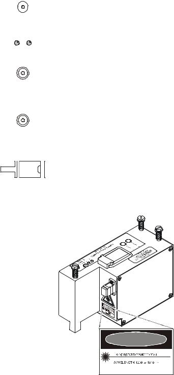
Figure 2 illustrates a top view of the SG2-DRT-3X.
Figure 2
SG2-DRT-3X transmitter
1 |
|
2 |
||
|
|
F |
|
|
OPTICAL |
|
|
||
A |
|
|
||
POWER |
U |
|
|
|
(1 V/mW) |
L |
|
O |
|
|
|
T |
|
N |
ALARM
3 4
SG2-DRT-3X
Digital Return Optical Transmitter
I |
I |
N |
N |
P |
P |
U |
U |
T |
T |
A |
B |
XXXXXX-XXX-XX
ITU/CH XX WAV XXXX.XX
XXXXXXXXXXX
5
SG2-DRT-3X Installation Sheet
STARLINE |
3 |
Table 1 provides information on the user-related features of the SG2-DRT-3X.
Key Feature
1 OPTICAL POWER (1 V/mW)
Description
This test point enables monitoring of the optical output level of the module. The nominal scale factor is 1.0 V/mW (6.3 V equates to 8 dBm). The optical power test point does not track changes in optical power due to the laser tracking error.
2 |
F |
|
|
A |
|
|
U |
O |
|
L |
|
|
T |
N |
ALARM
3
I
N
P
U
T
A
4
I
N
P
U
T
B
5
A red (FAULT) LED indicates that the laser output power is below normal limits.
A green LED (ON) indicates the transmitter is enabled.
Because the laser output requires a short period of time to stabilize, it is normal for neither LED to illuminate for approximately 10 seconds. The module must be enabled for the fault indicator to function.
This MCX connector provides the SG2-DRT-3X with channel A RF input through a cable connection to the node lid board in an SG2440 or the E-pack in an SG2000.
This MCX connector provides the SG2-DRT-3X with channel B RF input through a cable connection to the node lid board in an SG2440 or the E-pack in an SG2000.
Channel C RF input is provided by direct connection of the node lid board with the D-type connector on the bottom of the SG2-DRT-3X.
This SC/APC-type connector provides optical output from the SG2-DRT-3X.
Figure 3 illustrates a side view of the SG2-DRT-3X and indicates the laser warning label.
Figure 3
SG2-DRT-3X side view and laser warning label
DANGER |
INVISIBLE LASER RADIATION WHEN OPEN |
PEAK POWER 10 mW |
CLASS I LASER PRODUCT |
THIS PRODUCT COMPLIES WITH 21CFR |
CHAPTER 1 SUBCHAPTER J |
SG2-DRT-3X Installation Sheet
4 |
STARLINE |
Installing the SG2-DRT-3X in the SG2440 Node
The SG2440 carries each RF return path individually to the lid board and no adjustments to the electronics package (E-pack) are necessary.
Before you install the SG2-DRT-3X in the SG2440, you must configure the node with the SG2440 DR-3X board. In this configuration, the RF return signals from RP1 and RP3 are combined and placed onto the D-subconnector beneath the double-wide transmitter module. The RF return signals from RP2 are routed to the MCX connector DRT1. The RF return signals from RP4 are routed to the MCX connector DRT2. RF cables are used to route the signal from DRT1 and DRT2 to the top of the transmitter to RF INPUT A and RF INPUT B respectively.
If different combining scenarios are required, you may reconfigure the RF RP cables on the lid board.
Figure 4 illustrates a block diagram of the SG2440-DR-3X return configuration.
Figure 4
SG2440-DR-3X return configuration
|
|
|
|
|
|
|
|
|
|
|
|
|
|
|
|
|
|
|
|
|
|
|
|
|
|
|
|
|
|
|
|
|
|
|
|
|
|
E-PACK |
|
PLUG-IN |
|
|
LID |
XMTR |
|||||||||||||||||||||
|
|
|
|
|
|
|
|
|||||||||||||||||||||||||
|
|
|
|
|
|
|
|
|
|
|
|
|
RP1 |
|
BOARD |
|
|
TX |
|
|
INPUT |
|||||||||||
|
|
|
|
|
|
|
|
|
|
|
|
|
|
|
|
|
|
|||||||||||||||
|
|
|
|
|
|
|
|
|
|
|
|
|
|
|
|
|
|
|
|
C |
||||||||||||
|
|
|
|
|
|
|
|
|
|
|
|
|
|
|
|
|
|
|
|
|
|
|
|
|
|
|
|
|
|
|
||
|
|
|
|
|
|
|
|
|
|
|
|
|
|
|
|
|
|
|
|
|
|
|
|
|
|
|
|
|
|
|
||
|
|
|
|
|
|
|
|
|
|
|
|
|
RP3 |
|
|
|
|
D sub location |
|
|||||||||||||
|
|
|
|
|
|
|
|
|
|
|
|
|
|
|
|
|
|
|
|
|
|
|||||||||||
|
|
|
|
|
|
|
|
|
|
|
|
|
|
|
|
|
|
|
|
|
|
|
|
|
|
|
|
|
|
|
|
|
|
|
|
|
|
|
|
|
|
|
|
|
|
|
|
|
|
|
|
|
|
|
|
|
|
|
|
|
|
|
|
|
|
|
|
|
|
|
|
|
|
|
|
|
|
|
RP2 |
|
3.5 dB |
|
|
DRT1 |
|
A |
||||||||||||
|
|
|
|
|
|
|
|
|
|
|
|
|
|
|
|
|
||||||||||||||||
|
|
|
|
|
|
|
|
|
|
|
|
|
|
|
|
|
||||||||||||||||
|
|
|
|
|
|
|
|
|
|
|
|
|
|
|
|
|
|
|
|
|
|
|
|
|
|
|
|
|
(MCX) |
|
||
|
|
|
|
|
|
|
|
|
|
|
|
|
|
|
|
|
|
|
|
|
|
|
|
|
|
|
|
|
|
|||
|
|
|
|
|
|
|
|
|
|
|
|
|
|
|
|
|
|
|
|
|
|
|
|
|
|
|
|
|
|
|||
|
|
|
|
|
|
|
|
|
|
|
|
|
|
|
|
|
|
|
|
|
|
|
|
|
|
|
|
|
|
|
|
|
|
|
|
|
|
|
|
|
|
|
|
|
|
RP4 |
|
3.5 dB |
|
|
DRT2 |
|
B |
||||||||||||
|
|
|
|
|
|
|
|
|
|
|
|
|
|
|
|
|
||||||||||||||||
|
|
|
|
|
|
|
|
|
|
|
|
|
|
|
|
|
|
|
|
|
|
|
|
|
|
|
|
|
(MCX) |
|
||
|
|
|
|
|
|
|
|
|
|
|
|
|
|
|
|
|
|
|
|
|
|
|
|
|
|
|
|
|
|
|||
|
|
|
|
|
|
|
|
|
|
|
|
|
|
|
|
|
|
|
|
|
|
|
|
|
|
|
|
|
|
|||
|
|
|
|
|
|
|
|
|
|
|
|
|
|
|
|
|
|
|
|
|
|
|
|
|
|
|
|
|
|
|
|
|
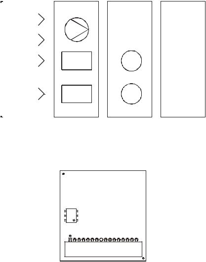
Figure 5 illustrates the SG2440-DR-3X return board.
Figure 5
SG2440-DR-3X return board
T1
R5 R6
|
|
|
|
|
|
|
|
|
|
|
|
|
|
|
|
|
|
|
|
|
|
|
|
|
|
|
|
|
|
|
|
|
|
|
|
|
|
|
|
|
|
|
|
|
|
|
R1 |
|
R2 |
|
|
|
R3 |
|
R4 |
|
||||||||||||
J9
SG2-DRT-3X Installation Sheet

STARLINE |
5 |
To install the SG2-DRT-3X in the SG2440 node:
1If present, remove any analog transmitter that occupies the optical XMTR B or A positions, as illustrated in Figure 6, and then install the double-wide SG2-DRT-3X.
Figure 6 SG2440 lid
TP XMTR B |
|
|
|
|
|
TP XMTR A |
|||||||||
|
|
|
|
||||||||||||
Pad XMTR B |
|
|
|
|
|
|
|
Pad XMTR A |
|||||||
|
|
|
|
|
|||||||||||
|
|
|
|
|
|
|
|
|
|
|
|
|
|
|
TP DRT1 |
Return configuration |
|
|
|
|
|
|
|
||||||||
|
|
|
Pad DRT1 |
||||||||||||
location |
|
|
|
||||||||||||
|
|
|
|
|
|
||||||||||
|
|
|
|
|
|
|
|
|
|
|
|
|
|
|
TP DRT2 |
|
|
|
|
|
|
|
|
|
|
|
|
|
|
||
|
|
|
|
|
|
|
|
|
|
|
|
|
Pad DRT2 |
||
|
|
|
|
|
|
|
|
|
|
|
|
|
|||
Optical XMTR B
RP1
RP3 |
Optical XMTR A |
RP2
RP4
DRT1
DRT2
2Replace the XMTR B 15 dB pad with a 5 dB pad.
3Install the SG2-DRT-3X board in the return configuration location on the lid board as illustrated in Figure 5.
4Ensure that the PIC cable is properly connected to the lid and E-pack connectors.
5Install the two RF cables from DRT MCX 1 and DRT MCX 2 to RF INPUT A and RF INPUT B respectively on top of the SG2-DRT-3X.
6Confirm that the green LED (ON) located on the top panel of the SG2-DRT-3X is illuminated to confirm enable status. A delay of approximately 10 seconds before illumination is normal.
7Review return-path system levels:
Each input of the SG2-DRT-3X is configured to drive the laser to the recommended level of +15 dBmV.
Use TP DRT1 and TP DRT2 (Figure 5) to monitor the levels of the segmented ports. Pad DRT1 and pad DRT2 are used to adjust the level into the transmitter.
Use TP XMTR B to monitor the levels of the two combined ports. Pad XMTR B is used to adjust the level into the transmitter.
SG2-DRT-3X Installation Sheet
Loading...