


RDM2080D
Table of contents
 Loading...
User Guide
RDM Series MURS
Two-Way Radios
RDM2020
RDM2080d


CONTENTS
English
i
CONTENTS
Contents . . . . . . . . . . . . . . . . . . . . . . . . . . . . i
Safety . . . . . . . . . . . . . . . . . . . . . . . . . . . . . . iv
Batteries and Chargers
Safety Information . . . . . . . . . . . . . . . . . . . . v
Introduction . . . . . . . . . . . . . . . . . . . . . . . . .1
FCC Licensing
Information . . . . . . . . . . . . . . . . . . . . . . . . . .3
Radio Overview . . . . . . . . . . . . . . . . . . . . . .4
Display Model – RDM2080d . . . . . . . . . . . . . .4
Non-Display Model –
RDM2020 . . . . . . . . . . . . . . . . . . . . . . . . . . . .5
Battery Features . . . . . . . . . . . . . . . . . . . . . . .9
Drop-in Tray Charger and
Power Supply . . . . . . . . . . . . . . . . . . . . . . . .10
Charging The Battery . . . . . . . . . . . . . . . . . .16
Installing Spring Action
Belt Clip. . . . . . . . . . . . . . . . . . . . . . . . . . . . .23
Getting Started . . . . . . . . . . . . . . . . . . . . . 24
Turning radio ON/OFF . . . . . . . . . . . . . . . . . 24
Adjusting volume . . . . . . . . . . . . . . . . . . . . . 24
Reading the Display
(RDM2080d Model) . . . . . . . . . . . . . . . . . . . 24
Selecting a Channel . . . . . . . . . . . . . . . . . . . 25
Talking and Monitoring. . . . . . . . . . . . . . . . . 25
Receiving a Call . . . . . . . . . . . . . . . . . . . . . . 25
Scan . . . . . . . . . . . . . . . . . . . . . . . . . . . . . . . 25
Signal Strength and Channel
Busy Indicators
(RDM2080d Model) . . . . . . . . . . . . . . . . . . . 26
Low Battery Alert . . . . . . . . . . . . . . . . . . . . . 27
Talk Range. . . . . . . . . . . . . . . . . . . . . . . . . . 27
Computer Programming
Software . . . . . . . . . . . . . . . . . . . . . . . . . . . . 28
Radio Cloning. . . . . . . . . . . . . . . . . . . . . . . . 30
Basic Configuration . . . . . . . . . . . . . . . . . . 31
Menu Options (RDM2080d
Model) . . . . . . . . . . . . . . . . . . . . . . . . . . . . . 31
Battery Save. . . . . . . . . . . . . . . . . . . . . . . . . 31

CONTENTS
English
ii
Battery Type Settings
(RDM2080d Model) . . . . . . . . . . . . . . . . . . . .32
Channel Alias
(RDM2080d Model) . . . . . . . . . . . . . . . . . . . .32
Clonning Mode . . . . . . . . . . . . . . . . . . . . . . .33
Roger Beep Tone
(End of Transmission Tone) . . . . . . . . . . . . .34
Keypad Beep (RDM2080d
Model) . . . . . . . . . . . . . . . . . . . . . . . . . . . . . .34
Keypad Lock/Unlock (RDM2080d
Model) . . . . . . . . . . . . . . . . . . . . . . . . . . . . . .34
VOX - Voice Operated Transmit . . . . . . . . . .35
iVOX - Internal Voice Operated
Transmit (RDM2080d Model) . . . . . . . . . . . .36
VOX/iVOX Sensitivity Settings
(RDM2080d Model) . . . . . . . . . . . . . . . . . . . .36
Nuisance Channel Delete . . . . . . . . . . . . . . .37
PL Defeat . . . . . . . . . . . . . . . . . . . . . . . . . . .38
Reset to Factory Defaults . . . . . . . . . . . . . . .38
Advanced Configuration . . . . . . . . . . . . . .39
Entering Advanced
Configuration Mode . . . . . . . . . . . . . . . . . . . .39
Frequency Selection . . . . . . . . . . . . . . . . . . 39
CTSS/DPL Codes . . . . . . . . . . . . . . . . . . . . 39
Auto Scan. . . . . . . . . . . . . . . . . . . . . . . . . . . 39
Advanced Configuration
(RDM2080d Model) . . . . . . . . . . . . . . . . . . . 40
Other Advanced
Configurations (RDM2080d Model) . . . . . . . 41
Call Tone . . . . . . . . . . . . . . . . . . . . . . . . 41
Microphone Gain Level . . . . . . . . . . . . . 41
Scramble . . . . . . . . . . . . . . . . . . . . . . . . 42
Side Button Preset to
Channel Select . . . . . . . . . . . . . . . . . . . 43
Advanced Configuration
(RDM2020 Model) . . . . . . . . . . . . . . . . . . . . 44
Reading Values Through
Beeps and LED Indicators . . . . . . . . . . . 45
Reading Frequency Values . . . . . . . . . . 46
Reading CTCSS/DPL Values . . . . . . . . 46
Reading Auto-Scan Values . . . . . . . . . . 47
Changing Values . . . . . . . . . . . . . . . . . . 47
Configuring a Frequency . . . . . . . . . . . . 47
Configuring a Code . . . . . . . . . . . . . . . . 48
Configuring Auto-Scan. . . . . . . . . . . . . . 48

CONTENTS
English
iii
Frequency and Code Charts . . . . . . . . . . .50
Use and Care . . . . . . . . . . . . . . . . . . . . . . .57
Troubleshooting . . . . . . . . . . . . . . . . . . . . . 58
Motorola Limited Warranty for
the United States and Canada . . . . . . . . . .62
Accessories . . . . . . . . . . . . . . . . . . . . . . . .66

SAFETY
English
iv
SAFETY
PRODUCT SAFETY AND RF
EXPOSURE COMPLIANCE
For a list of Motorola-approved, batteries, and
other accessories, visit the following website:
www.motorola.com/RDX
Before using this product,
read the RF energy
awareness information and
operating instructions in the
Product Safety and RF
Exposure booklet enclosed
with your radio to ensure
compliance with RF energy
exposure limits.
C a u t i o n

BATTERIES AND CHARGERS
SAFETY INFORMATION
English
v
BATTERIES AND
CHARGERS SAFETY
INFORMATION
This document contains important safety and
operating instructions. Read these instructions
carefully and save them for future reference.
Before using the battery charger, read all the
instructions and cautionary markings on
• the charger,
• the battery, and
• the radio using the battery
1. To reduce risk of injury, charge only
rechargeable Motorola-authorized
batteries. Other batteries may explode,
causing personal injury and damage.
2. Use of accessories not recommended by
Motorola may result in risk of fire, electric
shock, or injury.
3. To reduce risk of damage to the electric
plug and cord, pull by the plug rather than
the cord when disconnecting the charger.
4. An extension cord should not be used
unless absolutely necessary. Use of an
improper extension cord could result in
risk of fire and electric shock. If an
extension cord must be used, make sure
that the cord size is 18 AWG for lengths
up to 6.5 feet (2.0 m), and 16 AWG for
lengths up to 9.8 feet (3.0 m).
5. To reduce risk of fire, electric shock, or
injury, do not operate the charger if it has
been broken or damaged in any way.
Take it to a qualified Motorola service
representative.
6. Do not disassemble the charger; it is not
repairable and replacement parts are not
available. Disassembly of the charger
may result in risk of electrical shock or
fire.

BATTERIES AND CHARGERS
SAFETY INFORMATION
English
vi
7. To reduce risk of electric shock, unplug
the charger from the AC outlet before
attempting any maintenance or cleaning
OPERATIONAL SAFETY GUIDELINES
• Turn the radio OFF when charging battery.
• The charger is not suitable for outdoor use.
Use only in dry locations/conditions.
• Connect charger only to an appropriately
fused and wired supply of the correct
voltage (as specified on the product).
• Disconnect charger from line voltage by
removing main plug.
• The outlet to which this equipment is
connected should be nearby and easily
accessible.
• Maximum ambient temperature around the
power supply equipment must not exceed
40 °C (104 °F).
• Power output from the power supply unit
must not exceed the ratings stated on the
product label located at the bottom of the
charger.

INTRODUCTION
English
1
INTRODUCTION
Thank you for purchasing the Motorola® RDM
Series MURS Two-Way Radio. This radio is a
product of Motorola's more than 75 years of
experience as a world leader in the designing
and manufacturing of communications
equipment. The RDM Series MURS Two-Way
Radios provide cost-effective communications
for businesses such as retail stores,
restaurants, schools, construction sites,
manufacturing, property and hotel
management and more. Motorola Business
two-way radios are the perfect communications
solution for all of today's fast-paced industries.
Note: Read this user guide carefully to ensure you
know how to properly operate the radio
before use.
Business Radios,
RPSD 1C15, Motorola
8000 West Sunrise Boulevard
Plantation, Florida 33322
PACKAGE CONTENTS
• Radio with fixed antenna
• Spring Action Belt-Clip
• Lithium-Ion Battery
• Power Supply
•User Guide
• Warranty Card
• Drop-in Tray Charger
• Product Safety & RF Exposure Booklet

INTRODUCTION
English
2
For a copy of a large-print version of this user
guide or for product-related questions, contact:
1-800-448-6686 in the USA
1-800-461-4575 in Canada
1-866-522-5210 on your TTY (Text
Telephone)
For product information visit us at:
www.motorola.com/business
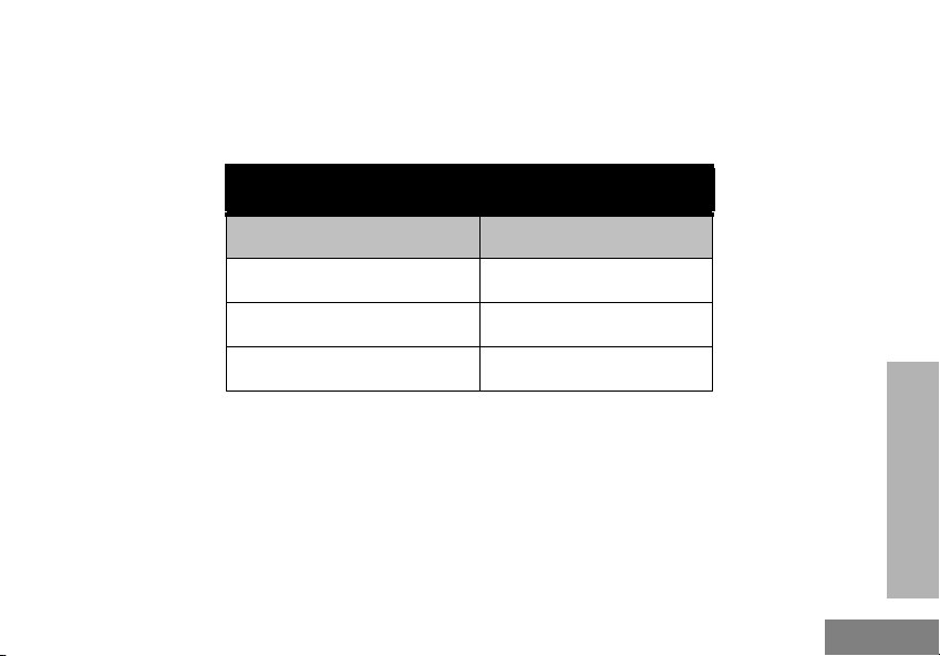
This User Guide covers the following RDM Series models:
Model
Frequency
Band
Transmit
Power
Number of
Channels
Display
RDM2080d MURS 2 W 8 Yes
RDM2020 MURS 2 W 2 No

FCC LICENSING
INFORMATION
English
3
FCC LICENSING
INFORMATION
REGULATION ON MURS (MULTI-USE
RADIO SERVICE) FREQUENCIES
The RDM2020/2080 radios are exclusively
MURS frequencies radios. These devices also
comply with Part 15 of the FCC Rules.
Operation is subject to the following two
conditions:
1. This device does not cause harmful
interference, and
2. This device must accept any interference
received, including interference that may cause
undesired operation.
FCC License is not required. This device
operates on frequencies authorized for use in
the Multi-Use Radio Service (MURS). MURS
frequencies are available for unlicensed
business or personal use. Take into account
that change or modifications not expressly
approved by Motorola may void the user’s
authority granted by the FCC to operate this
radio and should not be made. To comply with
FCC requirements, transmitter adjustments
should be made only by or under the
supervision of a person certified as technically
qualified to perform transmitter maintenance
and repairs in the private land mobile and fixed
services as certified by an organization
representative of the user of those services.
Replacement of any transmitter component
(crystal, semiconductor, etc.) not authorized by
the FCC equipment authorization for this radio
could violate FCC rules. Use of this radio
outside the country where it was intended to be
distributed is subject to government regulations
and may be prohibited.
For questions regarding FCC license, call
1-888-CALL-FCC (1-888-225-5322) or go to
www.fcc.gov.
RADIO OVERVIEW
English
4
RADIO OVERVIEW
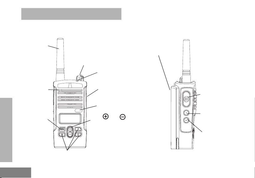
DISPLAY MODEL – RDM2080d
On/Off/
Volum e
Knob
Fixed
Antenna
Microphone
LED Indicator
Accessory
Connector
Model Label
Use and to scroll up/
down through channels and
menu setting
Front Buttons
PTT (Push-to-Talk)
Button
SB1 – Monitor
Button
SB2 – Nuisance
Channel Delete
Lithium-Ion
Battery
Menu Button/
Keypad Lock
RADIO OVERVIEW
English
5
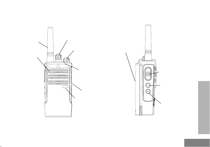
NON-DISPLAY MODEL – RDM2020
PTT (Push-to-Talk)
Button
SB1 – Monitor
Button
SB2 – Nuisance
Channel Delete
Fixed
Antenna
On/Off/Volume
Knob
LED Indicator
Accessory
Connector
Model Label
Microphone
Channel Selector
Knob
Lithium-Ion
Battery
RADIO OVERVIEW
English
6
On/Off/Volume Knob
Used to turn the radio ON or OFF and to adjust
the radio’s volume.
Channel Selector Knob
Used to switch the radio to different channels.
Accessory Connector
Used to connect compatible audio accessories.
Microphone
Speak clearly into the microphone when
sending a message.
Fixed Antenna
The antenna is not removable.
LED Indicator
Used to give battery status, power-up status,
radio call information and scan status.
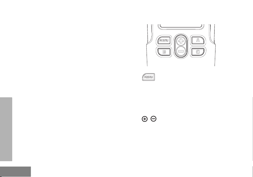
Front Buttons (RDM2080d Model Only)
• Button
This button provides access to set up features
like VOX/iVOX levels, battery type, etc. It also
allows for navigation through various features
while configuring the unit.
• Toggle Up/Down Buttons
Used to change channels and to scroll up/down
menu options or set up configurable values.
These buttons are not configurable.
RADIO OVERVIEW
English
7
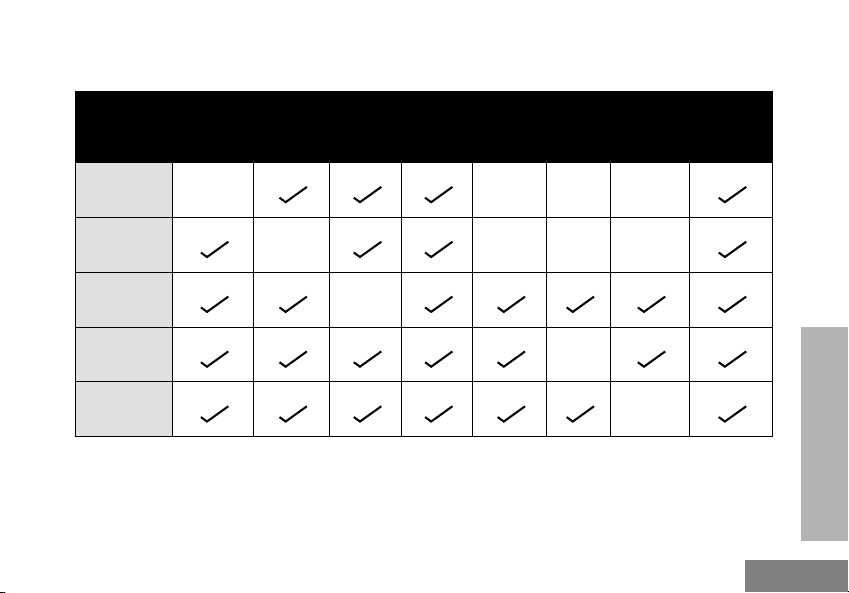
Configurable Buttons
Button Monitor
Sc a n /
Nuisance
Delete
Call Tone Scramble Backlight
Channel
Preset 1
Channel
Preset 2
No Operation
SB1 Default N/A N/A N/A
SB2 Default N/A N/A N/A
BUTTON A (*) Default
BUTTON B (*) Default
BUTTON C (*) Default
Buttons are configured to default functions, other features may be assigned to these buttons as
shown in the table.
(*) RDM2080d Model only
RADIO OVERVIEW
English
8
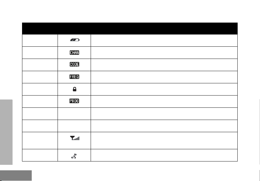
Icons Chart (RDM2080d Model)
Icon Symbol Comments
Battery Level Displayed during normal radio mode operation, displays battery life remaining.
Channel Displayed during normal radio operation and when programming channel features.
Code Displayed during normal radio operation and when programming codes features.
Frequency Displayed during normal radio operation.
Keypad lock Displayed whenever the Keypad lock feature is enabled (keypad is locked).
Program Displayed whenever the radio is set up to Advanced Configuration Mode.
Scan Displayed whenever the radio is set to SCAN mode.
Scramble Displayed whenever scramble is enabled.
Signal
Strength
RSSI Display Icon numbers of bars will indicate the strength of the received signal.
Vox/IVox Displayed when IVOX/VOX enabled or when programming MIC/MIC gain features.
G
L

RADIO OVERVIEW
English
9
BATTERY FEATURES
The RDM Series MURS Two-Way Radio
provides Lithium-Ion batteries that come in
different capacities that will define the battery
life. It also offers the option to use Alkaline
batteries.
About the Li-Ion Battery
The RDM Series MURS Two-Way Radio
comes equipped with a rechargeable Li-Ion
battery. This battery should be charged before
initial use to ensure optimum capacity and
performance.
Motorola batteries are designed specifically to
be used with a Motorola charger and vice
versa. Charging in non-Motorola equipment
may lead to battery damage and void the
battery warranty. The battery should be at
about 77 °F (25 °C) (room temperature),
whenever possible. Charging a cold battery
(below 50 ° F [10 °C]) may result in leakage of
electrolyte and ultimately in failure of the
battery. Charging a hot battery (above 95 °F
[35 °C]) results in reduced discharge capacity,
affecting the performance of the radio.
Motorola rapid-rate battery chargers contain a
temperature-sensing circuit to ensure that
batteries are charged within the temperature
limits stated above.
Battery Recycling and Disposal
Li-Ion rechargeable batteries can be recycled.
However, recycling facilities may not be
available in all areas. Under various U.S. state
laws and the laws of several other countries,
batteries must be recycled and cannot be
disposed of in landfills or incinerators. Contact
your local waste management agency for
specific requirements and information in your
area. Motorola fully endorses and encourages
the recycling of Li-Ion batteries. In the U.S. and
Canada, Motorola participates in the
nationwide Rechargeable Battery Recycling
Corporation (RBRC) program for Li-Ion battery
collection and recycling.

RADIO OVERVIEW
English
10
Many retailers and dealers participate in this
program. For the location of the drop-off facility
closest to you, access RBRC's Internet web
site at:
http://www.call2recycle.org/
or call:
1-800-8-BATTERY
This internet site and telephone number also
provides other useful information concerning
recycling options for consumers, businesses
and governmental agencies.
DROP-IN TRAY CHARGER AND POWER
SUPPLY
The radio is equipped with one Drop-in Tray
Charger and one Power Supply with Adaptor.
For details, see "Chargers” on page 67.
Drop-in Tray Charger
Power Supply
RADIO OVERVIEW
English
11
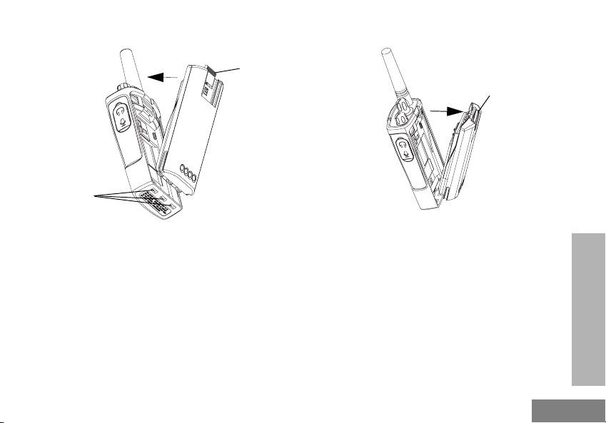
Installing the Battery
1. Turn OFF the radio.
2. With the Motorola logo side up, fit the tabs at
the bottom of the battery into the slots at the
bottom of the radio.
3. Press the top part of the battery towards the
radio until a click is heard.
Removing the Battery
1. Turn OF F the radio.
2. Push down and hold the battery latch.
3. Pull the top of the battery out and lift it from the
slots located at the bottom of the radio.
Battery
Latch
slots
Battery
Latch
RADIO OVERVIEW
English
12
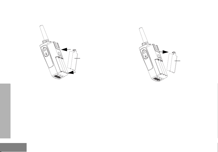
Alkaline Battery Pack (Optional)
Installing Alkaline Batteries
1. Turn OFF the radio and remove the Li-Ion
battery.
2. Assemble alkaline battery frame in the same
steps as installing the Li-Ion battery.
3. Pull the battery door from alkaline battery frame
out and slide five AA alkaline batteries into the
frame, matching the markings inside the
compartment.
4. Replace the battery door on the battery frame.
Removing Alkaline Batteries
1. Turn OFF the radio and remove the battery door
on the battery frame.
2. Remove the five AA alkaline batteries from the
battery frame.
3. Replace the battery door on the battery frame.
4. Slide the battery latches, on both sides of the
battery pack to remove the battery frame.
Alkaline
Battery
Door
Alkaline
Battery
Door
RADIO OVERVIEW
English
13
Li-Ion Battery Life
When the Battery Save feature is ON (enabled by default) the battery life will be longer. The
following chart summarizes battery life estimations:
Li-Ion Battery Life with Battery Save feature ON
Battery Type 2 Watts
Standard 12 hours
High 24 hours
Ultra High 26 hours
Note: Battery life is estimated based on the following standard
duty cycle: 5% Transmit, 5% Receive and 90% Standby.
RADIO OVERVIEW
English
14
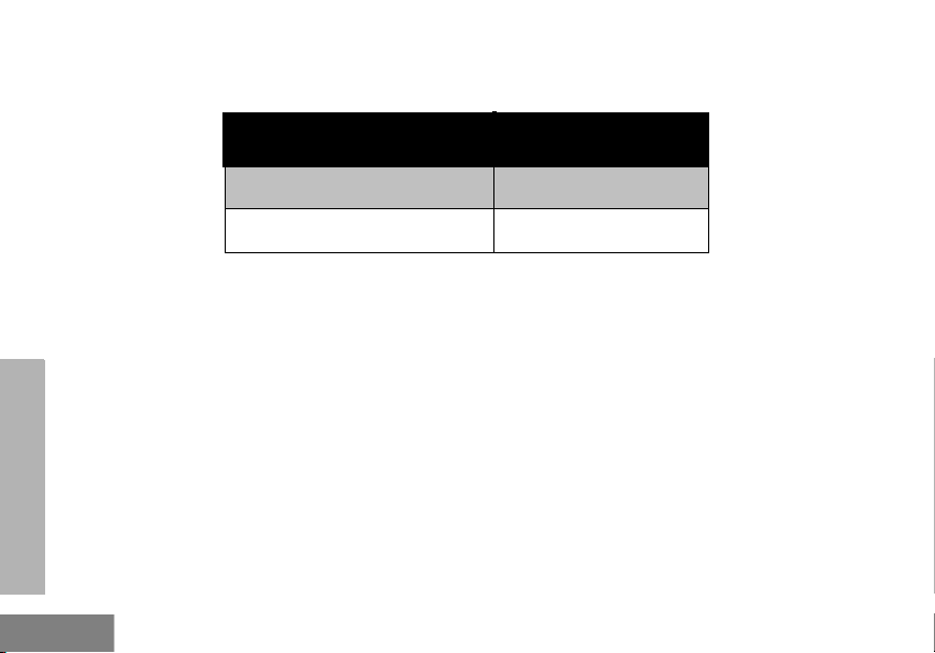
Alkaline Battery Life
The following chart estimates the Alkaline battery life:
Alkaline Battery Life
Battery Save Feature 2 Watts
ON 26 hours
Note: Battery life is estimated based on the following standard
duty cycle: 5% Transmit, 5% Receive and 90% Standby.
RADIO OVERVIEW
English
15
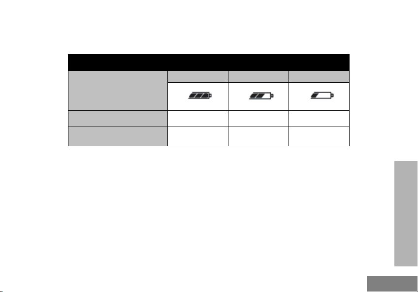
Battery Meter (RDM2080d Model)
The battery meter located in the upper left corner of the display model indicates the remaining
battery power.
RDM Series Battery Meter
Battery Type
3 Bars 2 Bars 1 Bar
Li-Ion 100% – 70% 70% – 30% 30% – 0%
AA 100% – 70% 70% – 30% 30% – 0%
RADIO OVERVIEW
English
16
CHARGING THE BATTERY
The RDM Series MURS Two-Way Radio offers
a Standard Charger and a Rapid Charger,
which are designed to charge either the battery
with the radio or a standalone battery.
The RDM radio comes equipped with a
Standard Charger.
Use only use Motorola-approved Drop-in Tray
Single Unit Charger or Drop-in Tray Multi Unit
Charger to charge the Motorola-approved
battery.
Note: When acquiring additional chargers or
power supplies, make sure you have similar
drop-in tray chargers and power supplies
sets (all “rapid” or all “standard”). For part
number details, refer to "Chargers” on
page 67.
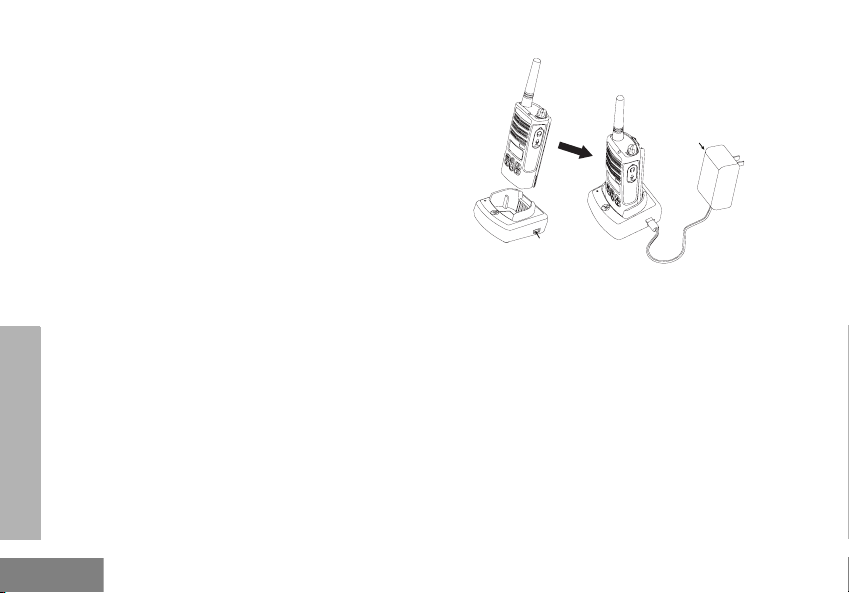
Charging The Battery Attached to the Radio
1. Place the drop-in tray charger on a flat surface.
2. Insert the connector of the power supply into the
port on the side of the drop-in tray charger.
3. Plug the AC adaptor into a power outlet.
4. Insert the radio with battery into the tray with the
front of the radio facing the front of the charger.
Note: Before charging a battery attached to a
radio, turn the radio OFF to ensure a full
charge. See "Operational Safety Guidelines”
on page vi for more information.
Power Supply
(Transformer)
Drop-in Tray
Charger Port
Loading...