


Air-Conditioner Control System
Power supply unit
Model: PAC-SC51KUA
Installation Manual
Contents
1. |
Safety Precautions ................................................... |
1 |
|
2. |
Product features....................................................... |
2 |
|
|
1. |
Specifications ................................................. |
2 |
|
2. |
Power supply capacity.................................... |
2 |
|
3. |
External Dimensions ...................................... |
3 |
3. |
Installation ................................................................ |
4 |
|
|
1. |
Parts List ........................................................ |
4 |
|
2. |
Field-supplied Parts........................................ |
4 |
|
3. |
Installation area and direction ........................ |
4 |
|
4. |
Unit installation ............................................... |
5 |
4. |
Wiring ....................................................................... |
5 |
|
|
1. |
Cover Removal and Installation ..................... |
5 |
|
2. |
Power line....................................................... |
6 |
|
3. |
DC Power Supply and M-NET Transmission |
|
|
|
Line................................................................. |
6 |
5. |
M-NET Transmission Lines Length........................ |
10 |
|
Before using the controller, please read this Installation Manual carefully to ensure proper operation. Retain this manual for future reference.

This manual details how to install the PAC-SC51KUA power supply unit and its wiring with the centralized controller and the indoor units. For the information about how to install the centralized controller or the indoor units, see the appropriate installation manual.
For your safety, first read 1 Safety Precautions described below before installing the PAC-SC51KUA.
Store this manual in as easily accessible location. Make sure that this manual will be passed on to any future PAC-SC51KUA power supply unit users.
 1 Safety Precautions
Read all the “Safety Precautions” before installing this unit.
Follow at the “Safety Precautions” ; the information provides very important points regarding safety.
Symbols and Terms
 WARNING Statements identify conditions or practices that could result in personal injury or loss of life.
 CAUTION Statements identify conditions or practices that could result in damage to the unit or other property.
Specific Precautions
 WARNING
The unit must be installed by a dealer or technical representative.
Improper installation by an unqualified person may result in electric shock and fire.
Install in a location that is strong enough to withstand the weight of the unit.
A weak installation area may cause the unit to fall down, resulting in a personal injury.
Only use specified cables. Securely connect each cable so that the weight of the cable is not applied to the connectors.
Loose or improper connections may result in heat generation or fire.
Do not attempt to modify or repair the controller.
Modification or improper repair may result in electric shock or fire.
Consult your dealer when repairs are necessary.
Make sure that the unit is powered by a dedicated line.
Other appliances connected to the same line could cause an overload.
Make sure that there is a main power switch and Ground-fault interrupter.
A ready accessible breaker for power source line helps reduce the risk of electric shock. Installation of a breaker is mandatory in some area.
Precisely follow the steps detailed in this manual for proper installation.
Any deficiency caused by improper installation may result in an electric shock or fire.
All electrical work must be performed by a licensed technician, according to local regulations and the instructions detailed in this manual.
Inadequate electric circuit or any deficiency caused by improper installation may result in an electric shock or fire.
Ask your dealer or an authorized technician to move or reinstall the controller.
Improper installation may result in an electric shock or fire.
This appliance must be grounded.
Make sure to install a protect PE (ground) wire.
Do not connect the PE (ground) wire to gas or water pipes, lightning conductors, or telephone lines.
Improper grounding may cause an electric shock.
Securely install the cover (panel) of the PAC-SC51KUA.
If the cover (panel) is not installed properly, dust or water may enter the unit and may result in fire or electric shock.
 CAUTION
Do not install the controller where there is a risk of flammable gas.
If the leaked gas accumulates around the controller, it may ignite and cause an explosion.
Do not use the controller in an environment high in oil, steam, or sulfuric gas.
These substances may have adverse effects on the performance of the controller or damage its parts.
Install so that the wires are not subjected to any tension.
Tension may cause the wires to break, overheating, or fire.
Do not wash the unit with water.
Doing so may cause an electric shock or malfunction.
Do not install in any area where the temperature could be more than 55°C (131°F) or less than -10°C (14°F). Do not expose to direct sunlight.
Use only a breaker and fuse of the specified capacity.
If breaker is not installed, it may cause an electric shock. If a fuse and wire or copper wiring that has too large of a capacity is used, it may cause the unit to malfunction or fire.
Do not install in a place that has the potential for steam such as bath room or kitchen.
Steam may cause an electric shock or unit malfunction.
Do not install in any place where acidic, alkaline solution, special spray, or other substances are used.
Doing so may cause an electric shock or unit malfunction.
Use standard wires in compliance with the current capacity.
A failure to do this may result in an electric leakage, overheating or fire.
Do not touch any PCB (Printed Circuit Board) with your hand or tools. Do not allow dust to collect on the PCB.
Doing so may cause fire or an electric shock.
- 1 -
 2 Product features
This unit supplies DC power to the centralized controller AG-150A via the centralized controller system M-NET transmission line and DC power line. Cannot be used with G-50A.
1. Specifications
Item |
|
|
Specifications |
|
|
|
|
|
|
Electrical requirements |
Rated input voltage |
100-240VAC ±10%; 0.8A - 0.4A 50Hz/60Hz Single-phase |
||
|
and current |
|||
|
|
|
|
|
|
Fuse: 250VAC 6.3A Time-delay type (IEC127-2 S.S.5) |
|||
|
|
|
|
|
Output voltage/current |
M-NET |
23.0 - 32.0VDC |
|
|
|
|
|
||
|
DC power supply |
24VDC ±5% 0 - 0.75A |
||
|
|
|
|
|
Load capacity (24V) |
Number of the loading unit: AG-150A Centralized Controller 1 unit |
|||
|
|
|
|
|
Environmental conditions |
Temperature |
Operating range |
|
-10 to +55ºC / +14 to +131ºF |
|
|
|
|
|
|
|
Storage range |
|
-20 to +60ºC / -4 to +140ºF |
|
|
|
|
|
|
Humidity |
30~90%RH (No condensation) |
||
|
|
|
|
|
Dimensions |
169 (H) × 271 (W) × 72 (D) mm (6-11/16 [H] × 10-11/16 [W] × 2-7/8 [D] in.) |
|||
Weight |
1.4 kg (3-1/8 lbs.) |
|
|
|
Installation Environment |
In the metal control panel or in the mounting attachment A type (PAC-YG85KTB) (sold separately) |
|||
|
* This unit is designed for a business office or similar environment. |
|||
2. Power supply capacity
2-1. 24V power supply (TB3)
Supplies power to one AG-150A unit.
Not connectable to multiple AG-150A units. Cannot be used with G-50A.
2-2. M-NET power supply (TB2)
PAC-SC51KUA is capable to supply equivalent power up to 5 (coefficient), therefore the maximum connectable number of system controller is as follows.
Table 1 Equivalent power consumption of controllers
|
Centralized controller |
Other system controllers |
M-NET remote controller |
|||
|
|
|
|
ON/OFF remote |
System remote controllers (SR) |
LOSSNAY remote |
|
AG-150A |
G-50A |
GB-50A |
Schedule timers (ST) |
||
|
controller |
controller |
||||
|
|
|
|
Group remote controllers (GR) |
||
|
|
|
|
|
|
|
Coefficient |
0.5 |
-*¹ |
3 |
1 |
0.5 |
0.25 |
*1. Cannot be used with G-50A. Use PAC-SC50KUA to connect G-50A. |
|
|
||||
Table 2 Maximum number of connectable controllers when using PAC-SC51KUA
Centralized controller |
|
|
|
Other system controllers |
|
|
M-NET remote controller |
||||||||
|
|
|
|
|
|
|
|
System remote controllers (SR) |
|
|
|
|
|||
AG-150A |
G-50A |
GB-50A |
|
ON/OFF remote controller |
|
Schedule timers (ST) |
|
LOSSNAY remote controller |
|||||||
|
|
|
|
|
|
|
|
Group remote controllers (GR) |
|
|
|
|
|||
|
|
|
|
|
|
|
|
|
|
|
|
|
|
|
|
1 unit*² |
-*¹ |
1 unit*² |
|
5 units |
|
|
|
|
10 units |
|
|
20 units |
|||
*1. Cannot be used with G-50A. Use PAC-SC50KUA to connect G-50A. |
|
|
|
|
|
|
|||||||||
*2. Either one AG-150A or one GB-50A can be connected. |
|
|
|
|
|
|
|
|
|
||||||
Table 3 Connectable number of system controllers when 1 AG-150A is used. |
|
|
|
|
V: Connectable |
||||||||||
|
|
|
|
|
|
|
|
|
|
|
|
|
|||
|
|
|
|
|
|
|
Total number of ON/OFF remote controllers (AN) |
|
|
||||||
|
|
|
|
|
|
0 |
1 |
|
2 |
3 |
|
4 |
|
5 |
|
|
|
|
|
|
|
|
|
|
|
|
|
|
|
|
|
|
|
|
|
0 |
|
V |
|
V |
|
V |
V |
|
V |
|
|
|
|
|
|
1 |
|
V |
|
V |
|
V |
V |
|
V |
|
|
|
|
|
|
2 |
|
V |
|
V |
|
V |
V |
|
|
|
|
Total number of |
|
|
3 |
|
V |
|
V |
|
V |
V |
|
|
|
|
|
System remote controllers (SR) |
|
4 |
|
V |
|
V |
|
V |
|
|
|
|
|
||
Schedule timers (ST) |
|
|
5 |
|
V |
|
V |
|
V |
|
|
|
|
|
|
Group remote controllers (GR) |
|
|
|
|
|
|
|
|
|
|
|
|
|
||
|
6 |
|
V |
|
V |
|
|
|
|
|
|
|
|||
|
|
|
|
7 |
|
V |
|
V |
|
|
|
|
|
|
|
|
|
|
|
8 |
|
V |
|
|
|
|
|
|
|
|
|
|
|
|
|
9 |
|
V |
|
|
|
|
|
|
|
|
|
- 2 -
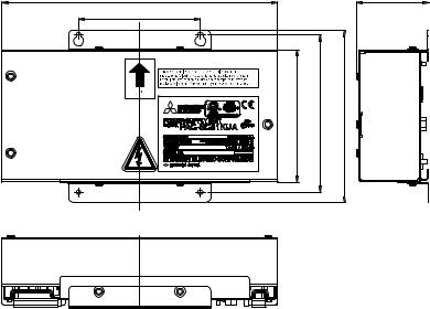
3. External Dimensions
271 (10-11/16) |
|
72 (2-7/8) |
90 (3-9/16) |
|
|
8 |
8 |
) |
16 |
||
) |
) |
|
/ |
/ |
/ |
1 |
1 |
|
5- |
6- |
11 |
( |
( |
6- |
130 |
155 |
( |
169 |
||
T |
|
|
TB2,TB3 |
TB1 |
Unit: mm (in.)
- 3 -
 Loading...