


OB307C
SERVICE MANUAL
CONTENTS
1. TECHNICAL CHANGES ····································2
2. PART NAMES AND FUNCTIONS······················6
3. INDOOR / OUTDOOR
CORRESPONDENCE TABLE ···························8
4. SPECIFICATION·················································9
5. NOISE CRITERIA CURVES·····························15
6. OUTLINES AND DIMENSIONS·······················18
7. WIRING DIAGRAM ··········································22
8. REFRIGERANT SYSTEM DIAGRAM··············28
9. PERFORMANCE CURVES······························40
10. MICROPROCESSOR CONTROL ····················75
11. SERVICE FUNCTIONS·····································86
12. TROUBLESHOOTING ······································88
13. DISASSEMBLY INSTRUCTIONS···················105
14. PARTS LIST····················································116
Wireless type
Models
MSC-A07WV -
(
WH
)
· MU-A07WV -
MSC-A09WV -
(
WH
)
· MU-A09WV -
MSC-A12WV -
(
WH
)
· MU-A12WV -
MSC-A07WV -
(
WH
)
· MUH-A07WV -
MSC-A09WV -
(
WH
)
· MUH-A09WV -
MSC-A12WV -
(
WH
)
· MUH-A12WV -
Multi system type
Models
MSC-A07WV -
(
WH
)
· MUX-A10WV -
MSC-A09WV -
(
WH
)
· MUX-A19WV -
MSC-A12WV -
(
WH
)
· MUX-A20WV -
· MUX-A25WV -
· MUX-A26WV -
E1
E1
E1E1
E1E1
E1E1
E1E1
E1E1
E1E1
E1E1
E1E1
E1E1
MSC-A07WV -
MSC-A09WV -
MSC-A12WV -
E1
E1
E1
No. OB307
REVISED EDITION-C
HFC
utilized
R410A
SPLIT-TYPE, AIR CONDITIONERS
SPLIT-TYPE, HEAT PUMP AIR CONDITIONERS
Revision C:
●MUX-A10/A19/A20/A25/A26WV - can be
connected to MSC-A07/A09/A12YV -
.
E1
E1
Indication of
model name
Remote
controller
NOTE:
•As for indoor units MSC-A07/A09/A12YV - , refer to the service manual OB329.
•As for outdoor units MUX-A22WV - , refer to the service manual OB318 REVISED EDITION-A.
•As for outdoor units MXZ-A18/A26/A32WV - , refer to the service manual OB319.
E1
E1
E1
Please void OB307 REVISED EDITION-B.
2
TECHNICAL CHANGES
1
MSC-07RV- ➔MSC-A07WV-
MSC-09RV- ➔MSC-A09WV-
MSC-12RV- ➔MSC-A12WV-
1. Rated voltage has changed. (220-240V➔230V)
2. Indoor model has changed.
MU-07RV- ➔MU-A07WV-
1. Refrigerant has changed. (R22➔R410A)
2. Compressor has changed. (RH130VGCT➔RN092VHSHT)
MU-09RV- ➔MU-A09WV-
1. Refrigerant has changed. (R22➔R410A)
2. Compressor has changed. (RH140VGCT➔RN099VHSHT)
MU-12RV- ➔MU-A12WV-
1. Refrigerant has changed. (R22➔R410A)
2. Compressor has changed. (RH220VHAT➔RN135VHSHT)
MUH-07RV- ➔MUH-A07WV-
1. Refrigerant has changed. (R22➔R410A)
2. Compressor has changed. (RH130VGCT➔RN092VHSHT)
MUH-09RV- ➔MUH-A09WV-
1. Refrigerant has changed. (R22➔R410A)
2. Compressor has changed. (RH165VGCT➔RN104VHSHT)
MUH-12RV- ➔MUH-A12WV-
1. Refrigerant has changed. (R22➔R410A)
2. Compressor has changed. (RH220VHAT➔RN135VHSHT)
MUX-10RV- ➔MUX-A10WV-
1. Outdoor model has changed.
2. Refrigerant has changed. (R22➔R410A)
MUX-19TV- ➔MUX-A19WV-
MUX-20TV- ➔MUX-A20WV-
MUX-25TV- ➔MUX-A25WV-
1. Refrigerant has changed. (R22➔R410A)
MUX-24RV- ➔MUX-A26WV-
1. Outdoor model has changed.
2. Refrigerant has changed. (R22➔R410A)
E1E2
E1E1
E1E1
E1E1
E1E2
E1E4
E1E4
E1E4
E1E4
E1E4
E1E4
E1E4
E1E4
E1E4
Revision C:
•MUX-A10/A19/A20/A25/A26WV - can be connected to MSC-A07/A09/A12YV -
.
E1E1
3
Refrigerating
oil
Refrigerant
New refrigerant
R410A
HFC-32: HFC-125 (50%:50%)
Pseudo-azeotropic refrigerant
Not included
A1/A1
72.6
-51.4
1.557
64
Non combustible
0
1730
From liquid phase in cylinder
Possible
Incompatible oil
Non
Non
Previous refrigerant
R22
R22 (100%)
Single refrigerant
Included
A1
86.5
-40.8
0.94
44.4
Non combustible
0.055
1700
Gas phase
Possible
Compatible oil
Light yellow
Non
Refrigerant
Composition (Ratio)
Refrigerant handling
Chlorine
Safety group (ASHRAE)
Molecular weight
Boiling point (:)
Steam pressure [25:](Mpa)
Saturated steam density [25:](Kg/K)
Combustibility
ODP w1
GWP w2
Refrigerant charge method
Additional charge on leakage
Kind
Color
Smell
w1:Ozone Destruction Parameter : based on CFC-11
w2 :Global Warmth Parameter : based on CO
2
INFORMATION FOR THE AIR CONDITIONER WITH R410A REFRIGERANT
• This room air conditioner adopts an HFC refrigerant (R410A) which never destroys the ozone layer.
• Pay particular attention to the following points, though the basic installation procedure is same as that for R22 conditioners.
1 As R410A has working pressure approximate 1.6 times as high as that of R22, some special tools and piping parts/
materials are required. Refer to the table below.
2 Take sufficient care not to allow water and other contaminations to enter the R410A refrigerant during storage and
installation, since it is more susceptible to contaminations than R22.
3 For refrigerant piping, use clean, pressure-proof parts/materials specifically designed for R410A. (Refer to 2. Refrigerant
piping.)
4 Composition change may occur in R410A since it is a mixed refrigerant. When charging, charge liquid refrigerant to prevent
composition change.
NOTE : The unit of pressure has been changed to MPa on the international system of units(SI unit system).
The conversion factor is: 1(MPa [Gauge]) =10.2(kgf/
ff
[Gauge])
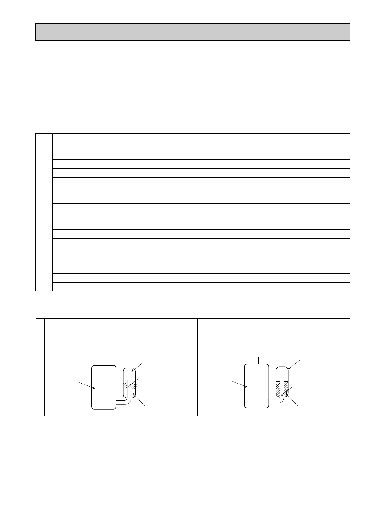
New Specification Current Specification
The incompatible refrigerating oil easily separates from
refrigerant and is in the upper layer inside the suction muffler.
Raising position of the oil back hole enables to back the
refrigerating oil of the upper layer to flow back to the
compressor.
Since refrigerant and refrigerating oil are compatible each,
refrigerating oil backs to the compressor through the lower
position oil back hole.
Compressor
Suction muffler
Oil back hole
Refrigerating oil
Refrigerant
Compressor
Suction muffler
Oil back hole
Refrigerating oil /Refrigerant
Compressor
4
-30 -20 -10 0 10 20
30
40 50 60
-0.5
0.0
0.5
1.0
1.5
2.0
2.5
3.0
3.5
4.0
(MPa [Gauge])
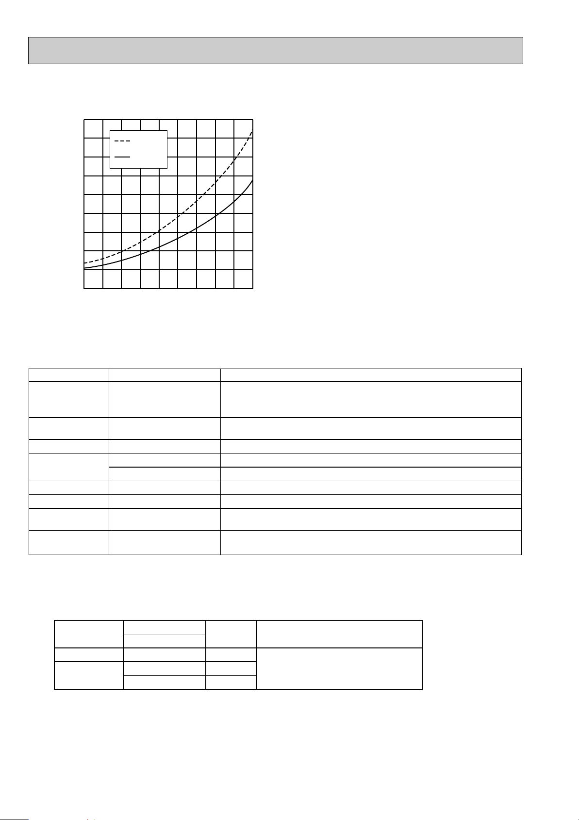
R410A
R22
Conversion chart of refrigerant temperature and pressure
Saturated liquid pressure
(:)
NOTE : The unit of pressure has been changed to MPa on the
international system of units(SI unit system).
The conversion factor is: 1(MPa [Gauge]) =10.2(kgf/
ff
[Gauge])
R410A tools Can R22 tools be used?
Gas leak detector
R410A has high pressures beyond the measurement range of existing
gauges. Port diameters have been changed to prevent any other refrigerant
from being charged into the unit.
Hose material and cap size have been changed to improve the pressure
resistance.
Dedicated for HFC refrigerant.
6.35 mm and 9.52 mm
Description
Clamp bar hole has been enlarged to reinforce the spring strength in the tool.
Provided for flaring work (to be used with R22 flare tool).
Provided to prevent the back flow of oil. This adapter enables you to use
vacuum pumps.
It is difficult to measure R410A with a charging cylinder because the
refrigerant bubbles due to high pressure and high-speed vaporization
No
No
No
Yes
Yes
New
New
New
Gauge manifold
Charge hose
Torque wrench
Flare tool
Flare gauge
Vacuum pump
adapter
Electronic scale for
refrigerant charging
No : Not Substitutable for R410A Yes : Substitutable for R410A
No 12.7 mm
1.Tools dedicated for the air conditioner with R410A refrigerant
The following tools are required for R410A refrigerant. Some R22 tools can be substituted for R410A tools.
The diameter of the service port on the stop valve in outdoor unit has been changed to prevent any other refrigerant being
charged into the unit. Cap size has been changed from 7/16 UNF with 20 threads to 1/2 UNF with 20 threads.
2.Refrigerant piping
1 Specifications
Use the refrigerant pipes that meet the following specifications.
• Use a copper pipe or a copper-alloy seamless pipe with a thickness of 0.8 mm. Never use any pipe with a thickness less
than 0.8mm, as the pressure resistance is insufficient.
Wall
thickness
Outside diameter
Pipe
mm
For liquid
For gas
6.35
9.52
12.7
0.8 mm
0.8 mm
0.8 mm
Heat resisting foam plastic
Specific gravity 0.045 Thickness 8 mm
Insulation material
5
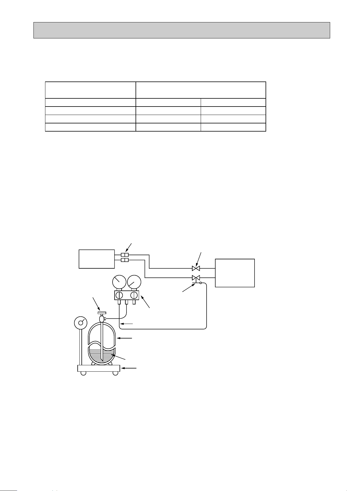
Electronic scale for refrigerant charging
Outdoor unit
Refrigerant gas
cylinder
operating valve
Refrigerant gas cylinder
for R410A with siphon
Refrigerant (liquid)
Service port
Gauge manifold
valve (for R410A)
Union
Liquid pipe
Gas pipe
Stop valve
Indoor unit
Charge hose (for R410A)
R410A
Pipe diameter
mm
6.35
9.52
12.7
17
22
26
Dimension of flare nut
R22
17
22
24
2 Flaring work and flare nut
Flaring work for R410A pipe differs from that for R22 pipe.
For details of flaring work, refer to Installation manual “FLARING WORK”.
3.Refrigerant oil
Apply the special refrigeration oil (accessories: packed with indoor unit) to the flare and the union seat surfaces.
4.Air purge
• Do not discharge the refrigerant into the atmosphere.
Take care not to discharge refrigerant into the atmosphere during installation, reinstallation, or repairs to the refrigerant
circuit.
• Use the vacuum pump for air purging for the purpose of environmental protection.
5.Additional charge
For additional charging, charge the refrigerant from liquid phase of the gas cylinder.
If the refrigerant is charged from the gas phase, composition change may occur in the refrigerant inside the cylinder and the
outdoor unit. In this case, ability of the refrigerating cycle decreases or normal operation can be impossible. However,
charging the liquid refrigerant all at once may cause the compressor to be locked. Thus, charge the refrigerant slowly.
6
PART NAMES AND FUNCTIONS
2
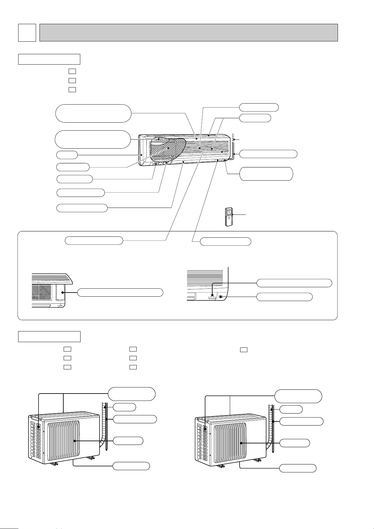
INDOOR UNIT
MSC-A07WV -
MSC-A09WV -
MSC-A12WV -
E1
E1
E1
Emergency operation switch
Operation section
Horizontal vane
Air filter
Air outlet
Deodorizing filter
(Gray sponge type)
Vertical vane
Air inlet
to Breaker
Remote control
receiving section
Remote controller
Display section
(When the front panel is opened)
Operation indicator lamp
Receiving section
Air cleaning filter
(White bellows type)
Power supply cord
Panel
Front panel
Air inlet
Piping
Drain hose
Air outlet
Drain outlet
(back and side)
Air inlet
Piping
Drain hose
Air outlet
Drain outlet
(back and side)
OUTDOOR UNIT
MU-A07WV - MUH-A07WV -
MU-A09WV - MUH-A09WV -
MU-A12WV - MUH-A12WV -
E1E1
E1E1
E1E1
MUX-A10WV-
E1
7
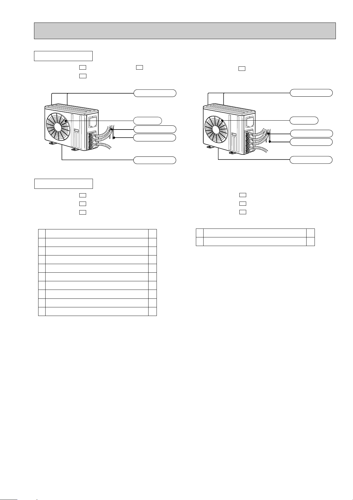
OUTDOOR UNIT
Air inlet
Piping
Drainage hose
(Back and side)
Air outlet
Drain outlet
MUX-A26WV-
E1
Air outlet
Drain outlet
Air inlet
Piping
Drainage hose
(Back and side)
MUX-A19WV- MUX-A25WV-
MUX-A20WV-
E1
E1E1
ACCESSORIES
MSC-A07WV-
MSC-A09WV-
MSC-A12WV-
E1
E1
E1
MUH-A07WV-
MUH-A09WV-
MUH-A12WV-
E1
E1
E1
Installation plate
Installation plate fixing screw 4 o 25 mm
Remote controller holder
Fixing screw for 3 3.5 o 16 mm
Battery (AAA) for remote controller
Wireless remote controller
Felt tape (Used for left or left-rear piping)
Deodorizing filter
Air cleaning filter
Refrigerant oil
1
5
1
2
2
1
1
1
1
1
<Indoor unit>
1
2
3
4
5
6
7
8
9
0
Drain socket
Drain cap
1
2
<Outdoor unit: MUH type>
1
2
8
MUX-A19WV-
E1
MUX-A25WV-
E1
MUX-A20WV-
E1
MUX-A10WV-
E1
MUX-A26WV-
E1
Combination of
the connectable
indoor units
OUTDOOR UNIT
A: MSC-A12WV- E1
or
MSC-A12YV-
E1
B: MSC-A07WV- E1
or
MSC-A07YV-
E1
A:
MSC-A09WV- E1
B:
or
C:
MSC-A09YV- E1
A:
B:
A:
B:
A:
MSC-A12WV- E1
or
B:
MSC-A12YV- E1
C:
MSC-A09WV- E1
or
D:
MSC-A09YV- E1
MSC-A12WV- E1
or
MSC-A12YV- E1
MSC-A07WV- E1
or
MSC-A07YV-
E1
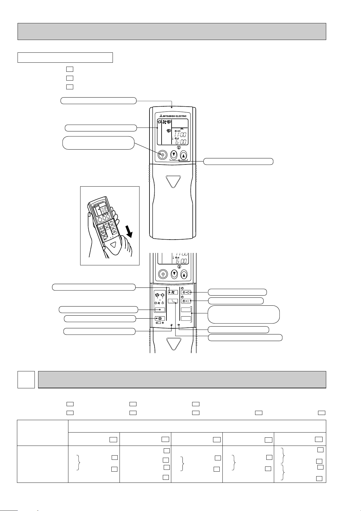
MSC-A07WV - MSC-A09WV - MSC-A12WV -
MUX-A10WV - MUX-A19WV - MUX-A20WV - MUX-A25WV - MUX-A26WV -
E1E1E1E1E1
E1E1E1
ON/OFF
FAN
TOO
WARM
TOO
COOL
VANE
MODE
ECONO COOL
STOP
START
HR.
MIN.
I FEEL
COOL
DRY
PM
CLOCK
AM
RESET
CLOCK
HEAT
/FAN
/
Open the front lid.
ON/OFF
TOO
COOL
PM
AM
TOO
WARM
Signal transmitting section
Operation display section
OPERATE /STOP
(ON /OFF)button
TEMPERATURE buttons
OPERATION SELECT button
FAN SPEED CONTROL button
OFF-TIMER button
HR. button
MIN. button
(TIME SET button)
ON-TIMER button
RESET button
ECONO COOL button
VANE CONTROL button
CLOCK SET button
REMOTE CONTROLLER
INDOOR / OUTDOOR CORRESPONDENCE TABLE3
MSC-A07WV -
MSC-A09WV -
MSC-A12WV -
E1
E1
E1
9
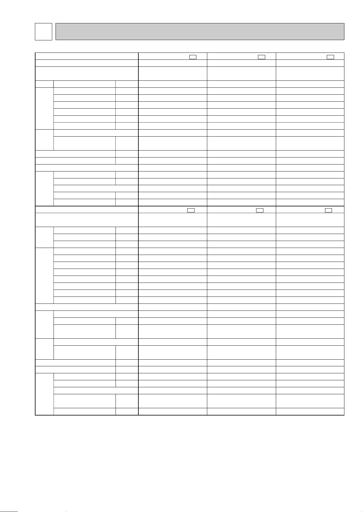
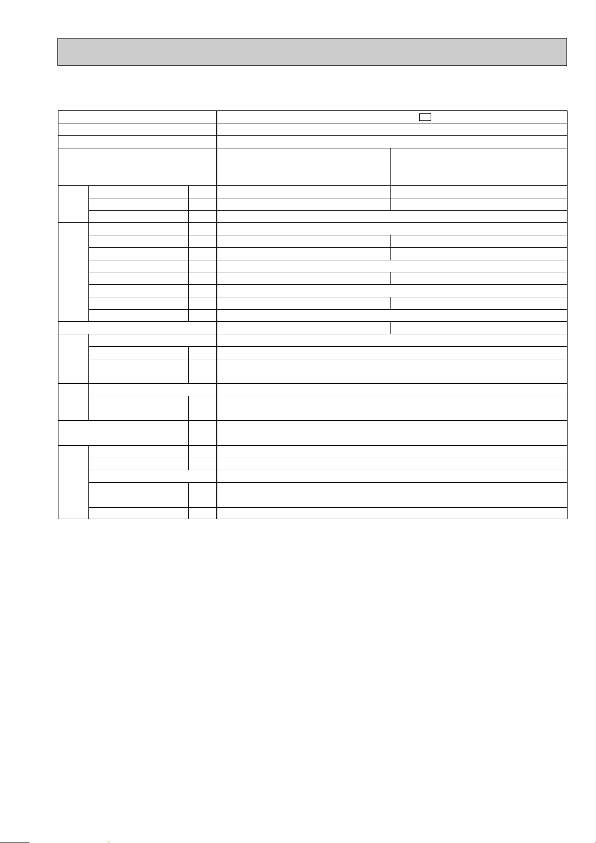
SPECIFICATION
4
Indoor model
Function
Indoor unit power supply
Air flow(High/Med. /Low )
Power outlet
Running current
Power input
Power factor
Starting current
Fan motor current
Model
Winding
resistance(at 20:)
Dimensions WOHOD
Weight
Air direction
Sound level(High/Med. /Low )
Fan speed (High/Med. /Low )
Fan speed regulator
Thermistor RT11(at 25:)
Thermistor RT12(at 25:)
Outdoor model
Capacity
Dehumidification
Outdoor air flow
Power outlet
Running current
Power input
Auxiliary heater
Power factor
Starting current
Compressor motor current
Fan motor current
Model
Output
Winding
resistance(at 20:)
Model
Winding
resistance(at 20:)
Dimensions WOHOD
Weight
Sound level
Fan speed
Fan speed regulator
Refrigerant filling
capacity (R410A)
Refrigerating oil (Model)
K /h
A
A
W
%
A
A
"
mm
kg
dB
rpm
k"
k"
kW
R/h
K /h
A
A
W
A(kW)
%
A
A
A
W
"
"
mm
kg
dB
rpm
kg
cc
MSC-A07WV -
E1
Single phase
230V,50Hz
10
0.17
35
90
—
0.17
WHT-BLK 413
BLK-RED 334
815O278O217
9
5
3
10
10
MU-A07WV -
E1
Single phase
230V,50Hz
10
—
2.76
0.22
RN092VHSHT
600
C-R 3.87
C-S 6.14
RA6V23-FC
WHT-BLK 353
BLK-RED 321
780o540o255
34
45
735
1
0.75
350 (NEO22 )
Cooling
474/372 /276
RC4V19-LA
36/31 /25
900/750 /600
2.3
0.9
1,686
2.98
675
98
23
3.24
MSC-A09WV - E1
Single phase
230V,50Hz
10
0.17
35
RC4V19-LA
WHT-BLK 413
BLK-RED 334
815O278O217
9
5
3
10
10
MU-A09WV -
E1
Single phase
230V,50Hz
10
—
RN099VHSHT
700
C-R 3.40
C-S 4.56
RA6V23-FC
WHT-BLK 353
BLK-RED 321
780o540o255
34
45
735
1
0.80
350 (NEO22 )
Cooling
474/384 /306
90
—
0.17
36/31 /25
900/770 /650
2.55
1.1
1,686
3.26
745
99
24
3.04
0.22
3.27
MSC-A12WV - E1
Single phase
230V,50Hz
582/444 /324
10
0.19
40
RC4V19-KA
WHT-BLK 316
BLK-RED 299
815O278O217
10
5
3
10
10
MU-A12WV -
E1
Single phase
230V,50Hz
1.6
1,914
10
4.91
—
97
29
RN135VHSHT
900
C-R 2.79
C-S 3.36
RA6V33-DC
WHT-BLK 301
BLK-RED 332
780o540o255
36
49
825
1
0.83
620 (NEO22)
Cooling
92
—
0.19
40/33 /26
930/760 /600
3.45
1,100
4.60
0.31
3.03
Electrical
data
Fan
motor
Special
remarks
Compressor
Electrical
data
Fan
motor
Special
remarks
Capacity
Coefficient of performance(C.O.P)
Outdoor unit power supply
Capacity
ww
ww
w
w
w
w
w
w
w
w
w
w
ww
w
w
ww
ww
w
w
NOTE: Test conditions are based on ISO 5151.
Cooling : Indoor DB27°C WB19°C
Outdoor DB35°C WB24°C
Indoor-Outdoor piping length : 5m
w Reference value
10
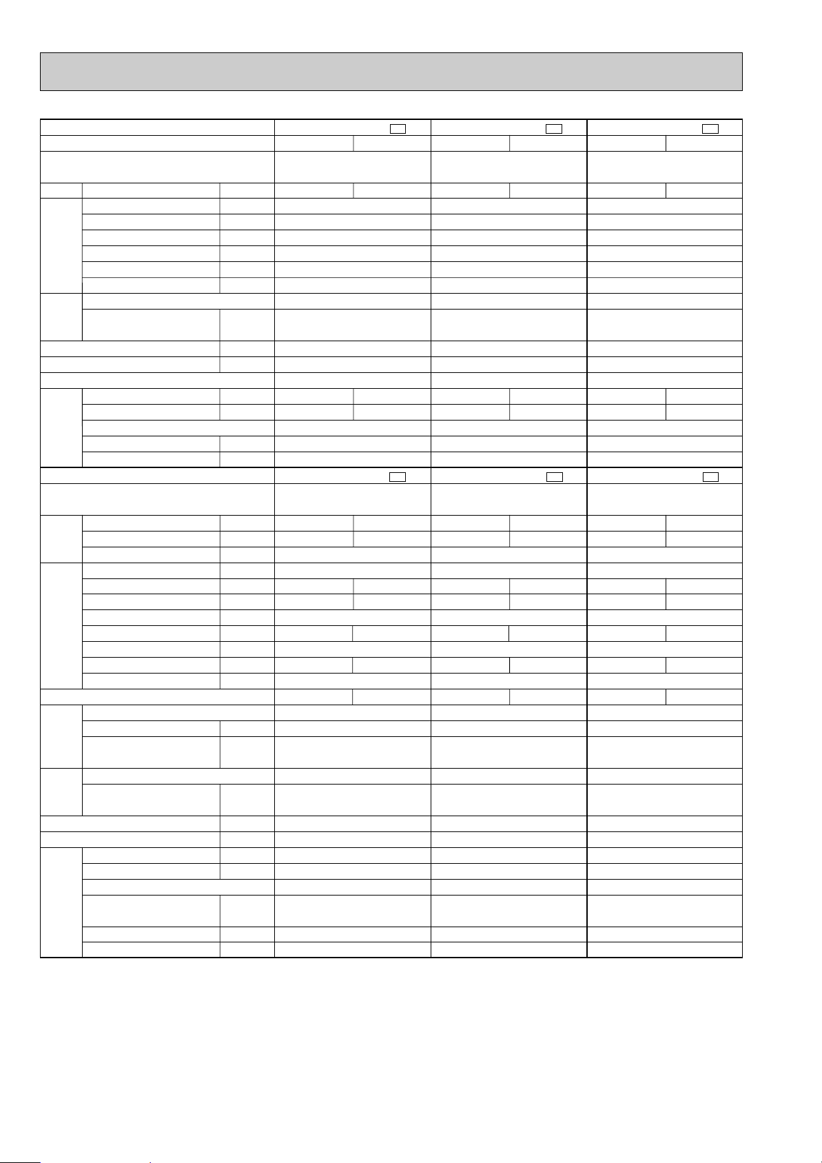
Indoor model
Function
Indoor unit power supply
Air flow(High/Med.
/Low
)
Power outlet
Running current
Power input
Power factor
Starting current
Fan motor current
Model
Winding
resistance(at 20:)
Dimensions WOHOD
Weight
Air direction
Sound level(High/Med. /Low )
Fan speed(High/Med. /Low )
Fan speed regulator
Thermistor RT11(at 25:)
Thermistor RT12(at 25:)
Outdoor model
Capacity
Dehumidification
Outdoor air flow
Power outlet
Running current
Power input
Auxiliary heater
Power factor
Starting current
Compressor motor current
Fan motor current
Model
Output
Winding
resistance (at 20:)
Model
Winding
resistance (at 20:)
Dimensions WOHOD
Weight
Sound level
Fan speed
Fan speed regulator
Refrigerant filling
capacity (R410A)
Refrigerating oil (Model)
Thermistor RT61 (at 0:)
K /h
A
A
W
%
A
A
"
mm
kg
dB
rpm
k"
k"
kW
R/h
K /h
A
A
W
A(kW)
%
A
A
A
W
"
"
mm
kg
dB
rpm
kg
cc
k"
MSC-A07WV -
E1
Single phase
230V,50Hz
10
0.17
35
90
—
0.17
RC4V19-LA
WHT-BLK 413
BLK-RED 334
815O278O217
9
5
3
10
10
MUH-A07WV -
E1
Single phase
230V,50Hz
1,686
10
—
23
0.22
RN092VHSHT
600
C-R 3.87
C-S 6.14
RA6V23-FB
WHT-BLK 353
BLK-RED 321
780o540o255
35
47
735
1
0.75
350 (NEO22)
33.18
Cooling
474/372 /276
36/31 /25
900/750 /600
2.3
0.9
2.98
675
98
2.76
3.24
Heating
510/420 /342
36/31 /25
950/820 /700
2.5
—
2.86
655
100
2.64
3.62
MSC-A09WV - E1
Single phase
230V,50Hz
10
0.17
35
90
—
0.17
RC4V19-LA
WHT-BLK 413
BLK-RED 334
815O278O217
9
5
3
10
10
MUH-A09WV -
E1
Single phase
230V,50Hz
1,710
10
—
24
0.31
RN104VHSHT
700
C-R 3.40
C-S 4.56
RA6V33-DB
WHT-BLK 301
BLK-RED 332
780o540o255
38
49
825
1
1.10
350 (NEO22)
33.18
Cooling
474/384 /306
36/31 /25
900/770 /650
2.55
1.1
3.26
745
99
2.95
3.27
Heating
588/456 /342
39/32 /25
1,050/870 /700
3.05
—
3.52
805
99
3.21
3.69
MSC-A12WV - E1
Single phase
230V,50Hz
10
0.19
40
92
—
0.19
RC4V19-KA
WHT-BLK 316
BLK-RED 299
815O278O217
10
5
3
10
10
MUH-A12WV -
E1
Single phase
230V,50Hz
1,710
10
—
29
0.31
RN135VHSHT
900
C-R 2.79
C-S 3.36
RA6V33-DB
WHT-BLK 301
BLK-RED 332
780o540o255
40
49
825
1
1.15
620 (NEO22)
33.18
Cooling
582/444 /324
40/33 /26
930/760 /600
3.4
1.6
4.51
1,020
98
4.20
3.21
Heating
606/498 /396
39/33 /26
960/830 /700
3.9
—
4.61
1,040
98
4.30
3.61
Electrical
data
Fan
motor
Special
remarks
Compressor
Electrical
data
Fan
motor
Special
remarks
Capacity
Coefficient of performance (C.O.P)
Outdoor unit power supply
Capacity
ww
ww
w
w
w
w
w
w
w
w
w
w
w
w
w
w
w
w
w
w
w
w
w
w
w
w
w
w
w
w
w
w
w
w
w
w
w
w
w
w
NOTE: Test conditions are based on ISO 5151.
Cooling : Indoor DB27°C WB19°C Heating : Indoor DB20°C
Outdoor DB35°C WB24°C Outdoor DB 7°C/WB 6°C
Indoor-Outdoor piping length : 5m
w Reference value
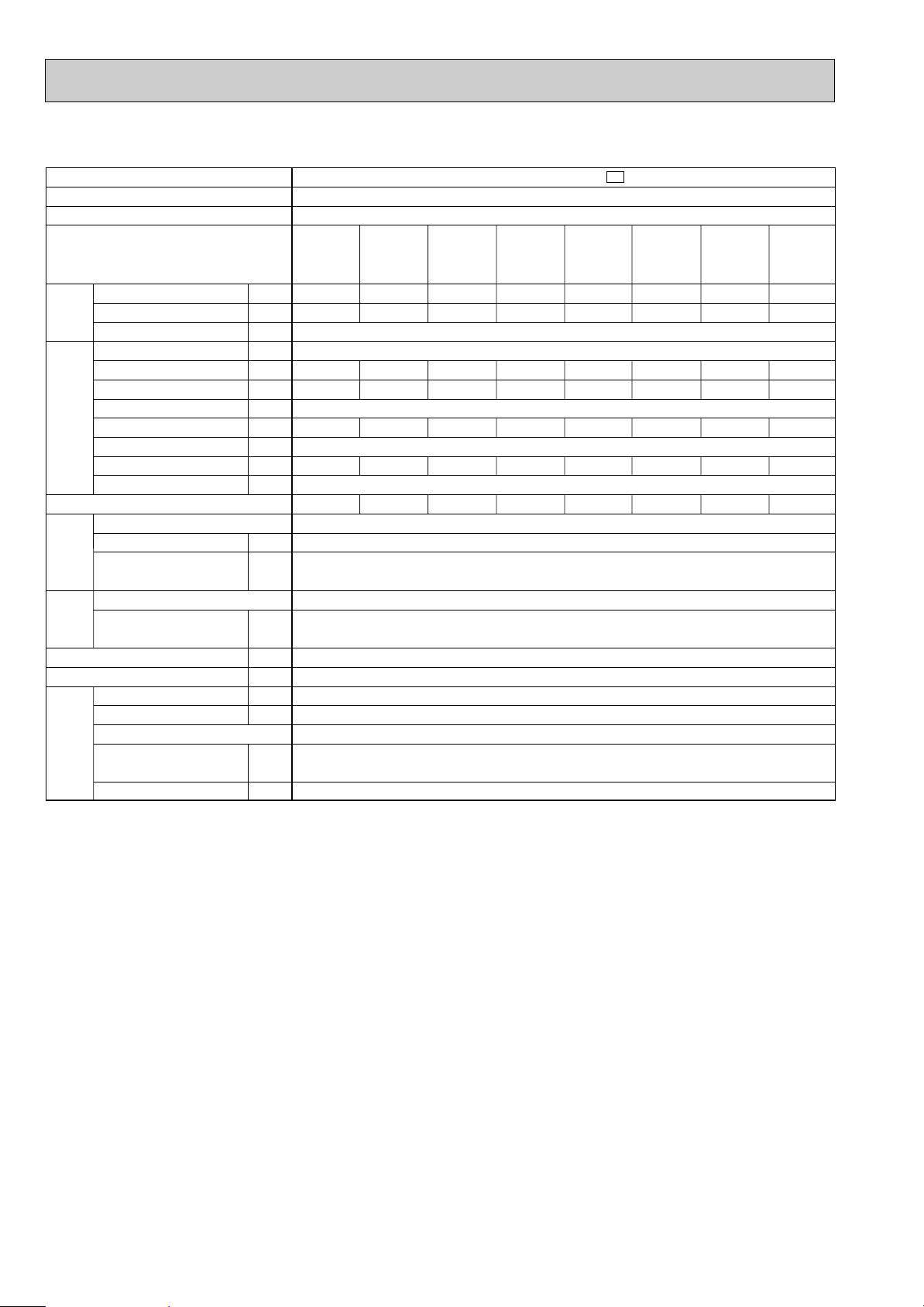
11
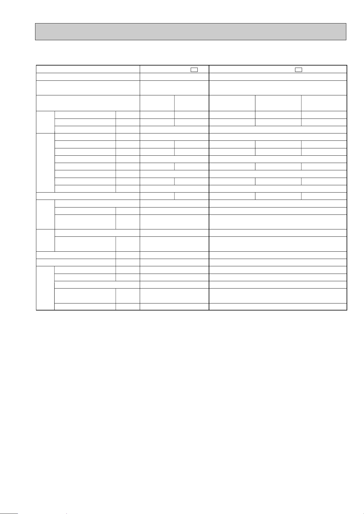
Outdoor model
Function
Capacity
Dehumidification
Outdoor air flow
Power outlet
Running current
Power input
Auxiliary heater
Power factor
Starting current
Compressor motor current
Fan motor current
Model
Output
Winding
resistance (at 20:)
Model
Winding
resistance (at 20:)
Dimensions WOHOD
Weight
Sound level
Fan speed
Fan speed regulator
Refrigerant filling
capacity (R410A)
Refrigerating oil (Model)
kW
R/h
K /h
A
A
W
A(kW)
%
A
A
A
W
"
"
mm
kg
dB
rpm
kg
cc
MUX-A10WV -
E1
Cooling
Single phase
230V,50Hz
1,914
10
—
21
0.29
RN092VHSHT
600
C-R 3.87
C-S 6.14
RA6V33-FC
WHT-BLK 223
BLK-RED 221
780O540O255
35
49
825
1
0.90 (Room A+B)
350 (NEO22)
Single
A or B
2.4
0.9
3.20
725
98.5
2.91
3.16
Single
A
3.5
1.4
5.73
1,280
97.1
5.16
2.65
Double
A+B
3.5+2.4
1.4+0.9
8.96
2,005
97.3
8.39
2.84
Double
A+B
1.4O2
0.2O2
3.25
730
97.7
2.96
3.50
MUX-A19WV -
E1
Cooling
Single phase
230V,50Hz
Compressor
Electrical
data
Fan
motor
Special
remarks
Capacity
Coefficient of performance (C.O.P)
Outdoor unit power supply
Indoor unit No.
Single
B
2.4
0.9
2,460
20
3.51
785
—
97.2
48
2.94
0.57
2.93
MC1 : RN145VHSHT, MC2 : RN092VHSHT
MC1 : 1,000, MC2 : 600
RA6V60-GA
WHT-BLK 90
BLK-RED 146
840O640O330
66
52
730
1
1.00 (Room A)
0.80 (Room B)
MC1 : 620 (NEO22), MC2 : 350 (NEO22)
C-R 2.43
C-S 3.80
MC1 : , MC2 :
C-R 3.87
C-S 6.14
NOTE: Test conditions are based on ISO 5151.
Cooling : Indoor DB27°C WB19°C Heating : Indoor DB20°C
Outdoor DB35°C WB24°C Outdoor DB 7°C/WB 6°C
Indoor-Outdoor piping length : 5m
NOTE: As for specification of indoor unit, refer to page 9 (MSC-A07/A09/A12WV) or OB329 (MSC-A07/A09/A12YV).
12
Outdoor model
Function
Capacity
Dehumidification
Outdoor air flow
Power outlet
Running current
Power input
Auxiliary heater
Power factor
Starting current
Compressor motor current
Fan motor current
Model
Output
Winding
resistance (at 20:)
Model
Winding
resistance (at 20:)
Dimensions WOHOD
Weight
Sound level
Fan speed
Fan speed regulator
Refrigerant filling
capacity (R410A)
Refrigerating oil (Model)
kW
R/h
K /h
A
A
W
A(kW)
%
A
A
A
W
"
"
mm
kg
dB
rpm
kg
cc
Single phase
230V,50Hz
Double
A+B or A+C
2.6+2.8
0.9+1.1
2,460
20
8.18
1,850
—
98.3
47
7.61
0.57
2.81
MC1 : RN099VHSHT, MC2 : RN125VHSHT
MC1 : 650, MC2 : 800
RA6V60-GA
WHT-BLK 90
BLK-RED 146
840O640O330
65
52
730
1
0.80 (Room A)
1.00 (Room B+C)
MC1 : 350 (NEO22), MC2 : 350 (NEO22)
MUX-A20WV -
E1
Cooling
Compressor
Electrical
data
Fan
motor
Special
remarks
Capacity
Coefficient of performance (C.O.P)
Outdoor unit power supply
Indoor unit No.
Single
A
2.6
0.9
3.64
815
97.3
3.07
3.06
Single
B or C
2.9
1.2
4.86
1,075
96.2
4.29
2.61
Double
B+C
1.75O2
0.3O2
4.86
1,090
97.5
4.29
3.02
Triple
A+B+C
2.5+1.75O2
0.8+0.3O2
8.41
1,885
97.5
7.84
3.02
C-R 3.40
C-S 4.56
MC1 : , MC2 :
C-R 2.86
C-S 5.72
NOTE: Test conditions are based on ISO 5151.
Cooling : Indoor DB27°C WB19°C Heating : Indoor DB20°C
Outdoor DB35°C WB24°C Outdoor DB 7°C/WB 6°C
Indoor-Outdoor piping length : 5m
NOTE: As for specification of indoor unit, refer to page 9 (MSC-A07/A09/A12WV) or OB329 (MSC-A07/A09/A12YV).
13
Outdoor model
Function
Capacity
Dehumidification
Outdoor air flow
Power outlet
Running current
Power input
Auxiliary heater
Power factor
Starting current
Compressor motor current
Fan motor current
Model
Output
Winding
resistance (at 20:)
Model
Winding
resistance (at 20:)
Dimensions WOHOD
Weight
Sound level
Fan speed
Fan speed regulator
Refrigerant filling
capacity (R410A)
Refrigerating oil (Model)
kW
R/h
K /h
A
A
W
A(kW)
%
A
A
A
W
"
"
mm
kg
dB
rpm
kg
cc
Compressor
Electrical
data
Fan
motor
Special
remarks
Capacity
Coefficient of performance (C.O.P)
Outdoor unit power supply
Indoor unit No.
MUX-A25WV -
E1
Cooling
Single phase 230V,50Hz
2,460
20
—
54
0.57
MC1 : RN145VHSHT, MC2 : RN145VHSHT
MC1 : 1,000, MC2 : 1,000
RA6V60-GA
WHT-BLK 90
BLK-RED 146
840O640O330
68
52
730
1
0.95 (Room A)
0.95 (Room B)
MC1 : 620 (NEO22), MC2 : 620 (NEO22)
Single
A or B
3.5
1.4
5.88
1,300
96.1
5.31
2.61
Double
A+B
3.5O2
1.4O2
11.49
2,540
96.1
10.92
2.67
C-R 2.43
C-S 3.80
MC1 : , MC2 :
C-R 2.43
C-S 3.80
NOTE: Test conditions are based on ISO 5151.
Cooling : Indoor DB27°C WB19°C Heating : Indoor DB20°C
Outdoor DB35°C WB24°C Outdoor DB 7°C/WB 6°C
Indoor-Outdoor piping length : 5m
NOTE: As for specification of indoor unit, refer to page 9 (MSC-A07/A09/A12WV) or OB329 (MSC-A07/A09/A12YV).
14
Outdoor model
Function
Capacity
Dehumidification
Outdoor air flow
Power outlet
Running current
Power input
Auxiliary heater
Power factor
Starting current
Compressor motor current
Fan motor current
Model
Output
Winding
resistance (at 20:)
Model
Winding
resistance (at 20:)
Dimensions WOHOD
Weight
Sound level
Fan speed
Fan speed regulator
Refrigerant filling
capacity (R410A)
Refrigerating oil (Model)
kW
R/h
K /h
A
A
W
A(kW)
%
A
A
A
W
"
"
mm
kg
dB
rpm
kg
cc
Compressor
Electrical
data
Fan
motor
Special
remarks
Capacity
Coefficient of performance (C.O.P)
Outdoor unit power supply
Indoor unit No.
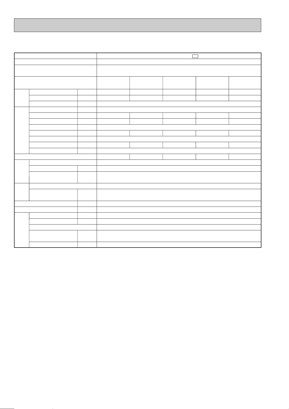
MUX-A26WV -
E1
Cooling
Single phase 230V,50Hz
2,760
20
—
52
0.53
MC1 : RN145VHSHT, MC2 : RN125VHSHT
MC1 : 1,000, MC2 : 800
RA6V60-FA
WHT-BLK 79
BLK-RED 80
840O850O330
76
52
730
1
1.05 (Room A+B)
1.05 (Room C+D)
MC1 : 620 (NEO22), MC2 : 350 (NEO22)
Single
A or B
3.4
1.2
5.28
1,180
97.2
4.75
2.79
Single
C or D
2.75
1.1
4.54
1,015
97.2
4.01
2.62
Double
A+B
1.95O2
0.2O2
5.46
1,210
96.4
4.93
3.02
Double
A+C or A+D
or
B+C or B+D
Triple
A+B+C
or
A+B+D
Triple
A+C+D
or
B+C+D
3.4+2.7
1.2+1.1
9.57
2,095
95.2
9.04
2.81
Double
C+D
1.7O2
0.3O2
4.78
1,060
96.4
4.25
3.01
1.95O2+2.8
0.2O2+1.1
9.61
2,105
95.2
9.08
3.02
3.4+1.7O2
1.2+0.3O2
9.66
2,140
96.3
9.13
3.02
Four
A+B+C+D
1.95O2+1.7O2
0.2O2+0.3O2
9.75
2,210
98.6
9.22
3.09
C-R 2.43
C-S 3.80
MC1 : , MC2 :
C-R 2.86
C-S 5.72
NOTE: Test conditions are based on ISO 5151.
Cooling : Indoor DB27°C WB19°C Heating : Indoor DB20°C
Outdoor DB35°C WB24°C Outdoor DB 7°C/WB 6°C
Indoor-Outdoor piping length : 5m
NOTE: As for specification of indoor unit, refer to page 9 (MSC-A07/A09/A12WV) or OB329 (MSC-A07/A09/A12YV).

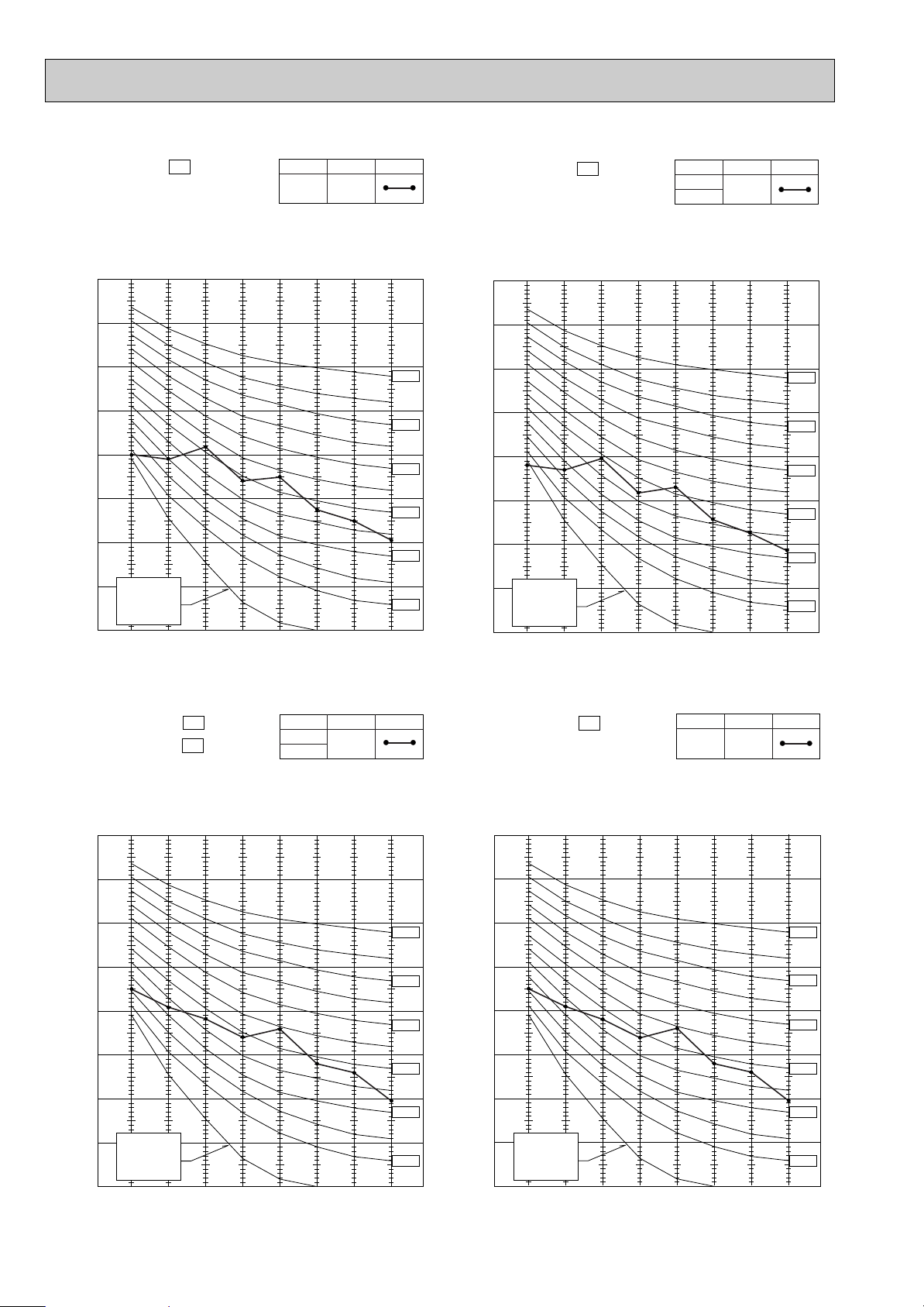
15
NOISE CRITERIA CURVES5
90
80
70
60
50
40
30
20
10
63 125 250 500 1000 2000 4000 8000
APPROXIMATE
TERESHOLD OF
HEARING FOR
CONTINUOUS
NOISE
NC-60
NC-50
NC-40
NC-30
NC-20
NC-70
OCTAVE BAND SOUND PRESSURE LEVEL, dB re 0.0002 MICRO BAR
BAND CENTER FREQUENCIES, Hz
Test conditions,
Cooling : DB27: WB19:
Heating : DB20: WB -:
MSC-A07WV- E1
COOL
High
FUNCTIONFAN SPEED
36
HEAT
SPL(dB
(A)) LINE
90
80
70
60
50
40
30
20
10
63 125 250 500 1000 2000 4000 8000
APPROXIMATE
TERESHOLD OF
HEARING FOR
CONTINUOUS
NOISE
NC-60
NC-50
NC-40
NC-30
NC-20
NC-70
OCTAVE BAND SOUND PRESSURE LEVEL, dB re 0.0002 MICRO BAR
BAND CENTER FREQUENCIES, Hz
Test conditions.
Cooling : DB27: WB19:
Heating : DB20: WB -:
MSC-A09WV- E1
COOL
High
FUNCTIONFAN SPEED
36
HEAT 39
SPL(dB
(A)) LINE
90
80
70
60
50
40
30
20
10
63 125 250 500 1000 2000 4000 8000
APPROXIMATE
TERESHOLD OF
HEARING FOR
CONTINUOUS
NOISE
NC-60
NC-50
NC-40
NC-30
NC-20
NC-70
OCTAVE BAND SOUND PRESSURE LEVEL, dB re 0.0002 MICRO BAR
BAND CENTER FREQUENCIES, Hz
Test conditions,
Cooling : DB27: WB19:
MSC-A12WV- E1
COOL
FUNCTIONFAN SPEED
40
HEAT
High
39
SPL(dB
(A)) LINE
90
80
70
60
50
40
30
20
10
63 125 250 500 1000 2000 4000 8000
APPROXIMATE
TERESHOLD OF
HEARING FOR
CONTINUOUS
NOISE
NC-60
NC-50
NC-40
NC-30
NC-20
NC-70
OCTAVE BAND SOUND PRESSURE LEVEL, dB re 0.0002 MICRO BAR
BAND CENTER FREQUENCIES, Hz
Test conditions,
Cooling : DB27: WB19:
MU-A07WV- E1
MU-A09WV- E1
COOL
FUNCTION
45
SPL(dB(A)) LINE
16
90
80
70
60
50
40
30
20
10
63 125 250 500 1000 2000 4000 8000
APPROXIMATE
TERESHOLD OF
HEARING FOR
CONTINUOUS
NOISE
NC-60
NC-50
NC-40
NC-30
NC-20
NC-70
OCTAVE BAND SOUND PRESSURE LEVEL, dB re 0.0002 MICRO BAR
BAND CENTER FREQUENCIES, Hz
Test conditions,
Cooling :DB35: WB24:
Heating :DB 7: WB 6:
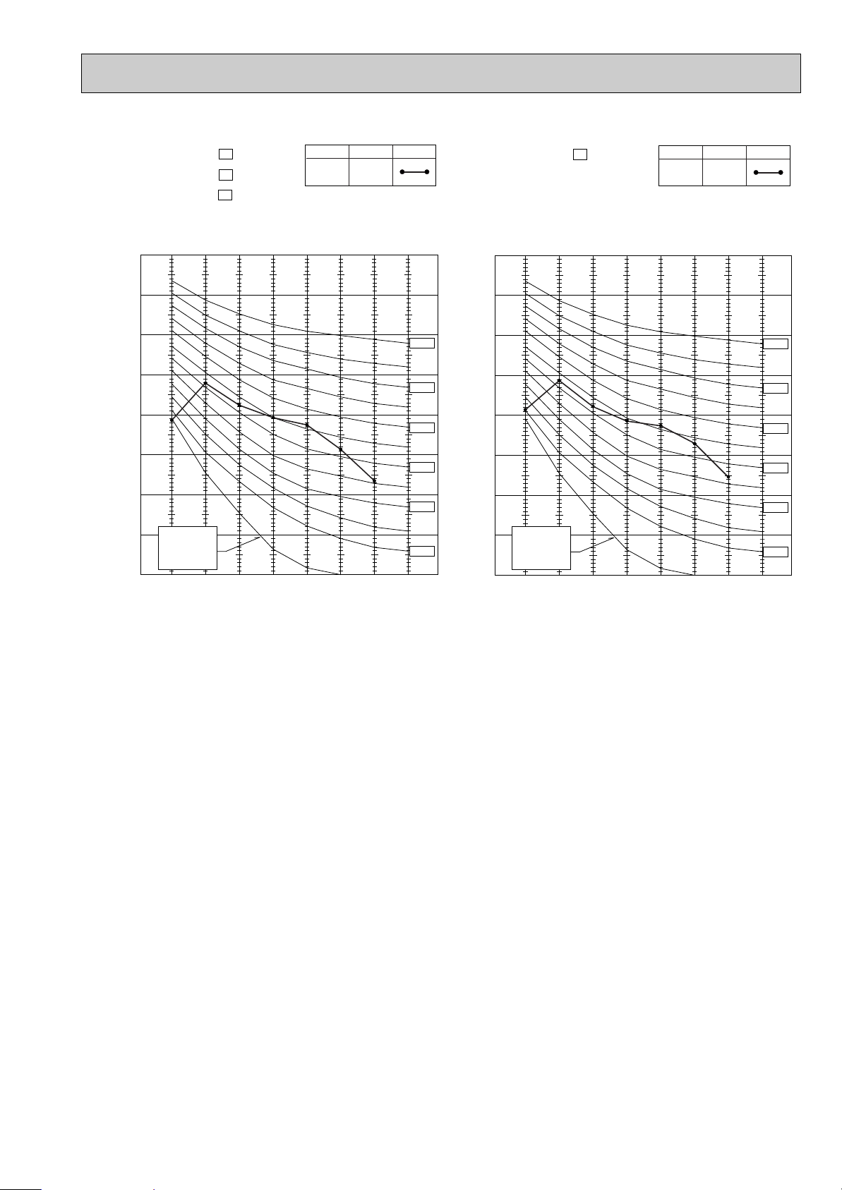
MUH-A09WV- E1
MUH-A12WV- E1
COOL
FUNCTION
49
HEAT
SPL(dB
(A)) LINE
90
80
70
60
50
40
30
20
10
63 125 250 500 1000 2000 4000 8000
APPROXIMATE
TERESHOLD OF
HEARING FOR
CONTINUOUS
NOISE
NC-60
NC-50
NC-40
NC-30
NC-20
NC-70
OCTAVE BAND SOUND PRESSURE LEVEL, dB re 0.0002 MICRO BAR
BAND CENTER FREQUENCIES, Hz
Test conditions.
Cooling : DB27: WB19:
MUX-A10WV- E1
COOL
FUNCTION
49
SPL(dB(A)) LINE
90
80
70
60
50
40
30
20
10
63 125 250 500 1000 2000 4000 8000
APPROXIMATE
TERESHOLD OF
HEARING FOR
CONTINUOUS
NOISE
NC-60
NC-50
NC-40
NC-30
NC-20
NC-70
OCTAVE BAND SOUND PRESSURE LEVEL, dB re 0.0002 MICRO BAR
BAND CENTER FREQUENCIES, Hz
Test conditions,
Cooling :DB35: WB24:
Heating :DB 7: WB 6:
MUH-A07WV- E1
COOL
FUNCTION
47
HEAT
SPL(dB
(A)) LINE
90
80
70
60
50
40
30
20
10
63 125 250 500 1000 2000 4000 8000
APPROXIMATE
TERESHOLD OF
HEARING FOR
CONTINUOUS
NOISE
NC-60
NC-50
NC-40
NC-30
NC-20
NC-70
OCTAVE BAND SOUND PRESSURE LEVEL, dB re 0.0002 MICRO BAR
BAND CENTER FREQUENCIES, Hz
Test conditions,
Cooling :DB35: WB24:
MU-A12WV- E1
COOL
FUNCTION
49
SPL(dB(A)) LINE
17
90
80
70
60
50
40
30
20
10
63 125 250 500 1000 2000 4000 8000
APPROXIMATE
TERESHOLD OF
HEARING FOR
CONTINUOUS
NOISE
NC-60
NC-50
NC-40
NC-30
NC-20
NC-70
OCTAVE BAND SOUND PRESSURE LEVEL, dB re 0.0002 MICRO BAR
BAND CENTER FREQUENCIES, Hz
Test conditions.
Cooling :DB35: WB24:
COOL
FUNCTION
52
SPL(dB(A)) LINE
MUX-A19WV - E1
MUX-A20WV - E1
MUX-A25WV - E1
90
80
70
60
50
40
30
20
10
63 125 250 500 1000 2000 4000 8000
APPROXIMATE
TERESHOLD OF
HEARING FOR
CONTINUOUS
NOISE
NC-60
NC-50
NC-40
NC-30
NC-20
NC-70
OCTAVE BAND SOUND PRESSURE LEVEL, dB re 0.0002 MICRO BAR
BAND CENTER FREQUENCIES, Hz
Test conditions.
Cooling :DB35: WB24:
COOL
FUNCTION
52
SPL(dB(A)) LINE
MUX-A26WV - E1
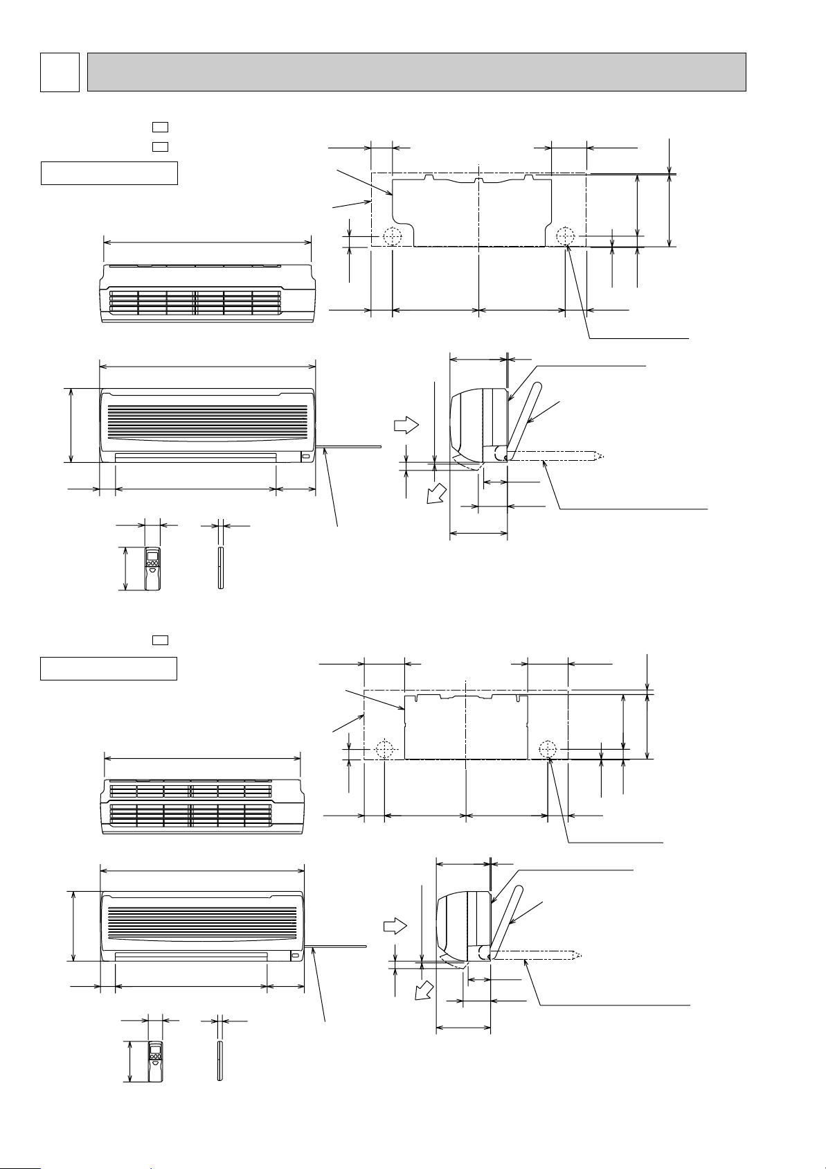
OUTLINES AND DIMENSIONS
18
6
MSC-A07WV -
MSC-A09WV -
E1
E1
MSC-A12WV -
E1
INDOOR UNIT
INDOOR UNIT
217
215
81.5
81.5
41
2.5
42
271
231.5
4.5
81.5
133.5
326326
162
19
58
5
7 or more
90
110
30
149
606
278
60
815
783
Wall hole
[65
Indoor unit
Installation plate
Installation plate
Insulation
[28
Drain hose
[16
(Connected part O,D)
Air in
Air out
Power supply cord
Lead to right 1.0m
Lead to left 0.3m
Wireless remote controller
Liquid line
[6.35-0.5m
Gas line
[9.52-0.43m
Insulation
[37 O.D
[21 I.D
{
217
215
218.5
258
81.581.5
41
42
2.5
17.5
161.5
161.5
326326
162
19
58
5
7 or more
90
110
30
149
606
278
60
815
783
Indoor unit
Installation plate
Wall hole
[65
Installation plate
Insulation
[28
Drain hose
[16
(Connected part O,D)
Air in
Air out
Power supply cord
Lead to right 1.0m
Lead to left 0.3m
Wireless remote controller
Liquid line
[6.35-0.5m
Gas line
[9.52-0.43m
Insulation
[37 O.D
[21 I.D
{
Unit: mm
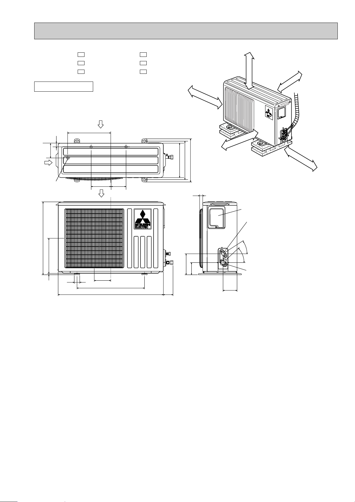
19
320
25
43-
35-
155
90
104
74
260
10
780
500
122
40
540
320
285
255
Service panel
Gas refrigerant
pipe joint
Refrigerant pipe
(flared) [9.52 (MU-A07/A09WV
)
(MUH-A07/A09WV
)
[12.7 (MU-A12WV
)
(MUH-A12WV
)
Liquid refrigerant
pipe joint
Refrigerant pipe
(flared) [6.35
Air out
Air in
Air in
109
32
110
147
Drainage
3holes [33
100mm or more
100mm or more
100mm or more
350mm or more
REQUIRED SPACE
400mm or more
Unit: mm
OUTDOOR UNIT
MU-A07WV - MUH-A07WV -
MU-A09WV - MUH-A09WV -
MU-A12WV - MUH-A12WV -
E1E1
E1E1
E1E1
20
320
25
10-
126
76
120
56
260
10
780
500
122
40
540
320
285
255
Service panel
Gas refrigerant
pipe joint
Refrigerant pipe
(flared) [9.52
Liquid refrigerant
pipe joint
Refrigerant pipe
(flared) [6.35
Air out
Air in
Air in
176
226
109
32
110
147
Drainage
3holes [33
100mm or more
100mm or more
100mm or more
350mm or more
REQUIRED SPACE
400mm or more
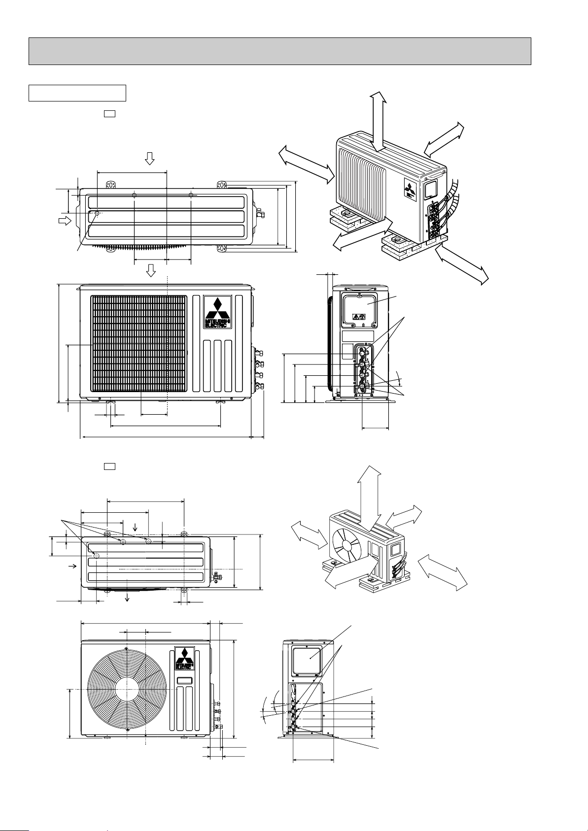
MUX-A10WV-
E1
OUTDOOR UNIT
Unit: mm
MUX-A19WV-
E1
500
840 61
264
10°
10°
Service panel
Open as a rule
500mm or more if
the front and both
sides are open
100mm or more
200mm or more if
there are obstacles
to both sides
Open as a rule
500mm or more if the back,
both sides and top are open
350mm or more
100mm or more
B UNIT
A UNIT
Gas refrigerant
pipe joint
Refrigerant pipe
(flared) {9.52
Gas refrigerant
pipe joint
Refrigerant pipe
(flared) {12.7
Liquid refrigerant
pipe joint
Refrigerant pipe
(flared) {6.35
65
80
121
40
438
Air in
Air out
Air in
273
100
125
320
30
330
640
360
76
505050
Drainage
3holes {33
}
}
34
21
MUX-A20WV-
E1
OUTDOOR UNIT
500
840 61
264
10°
10°
Service panel
Open as a rule
500mm or more if
the front and both
sides are open
100mm or more
200mm or more if
there are obstacles
to both sides
Open as a rule
500mm or more if the back,
both sides and top are open
350mm or more
100mm or more
B UNIT
A UNIT
Gas refrigerant
pipe joint
Refrigerant pipe
(flared) {9.52
Liquid refrigerant
pipe joint
Refrigerant pipe
(flared) {6.35
65
121
40
438
Air in
Air out
Air in
273
100
125
320
30
330
640
360
76
5050505050
Drainage
3holes {33
}
C UNIT
}
}
34
Unit: mm
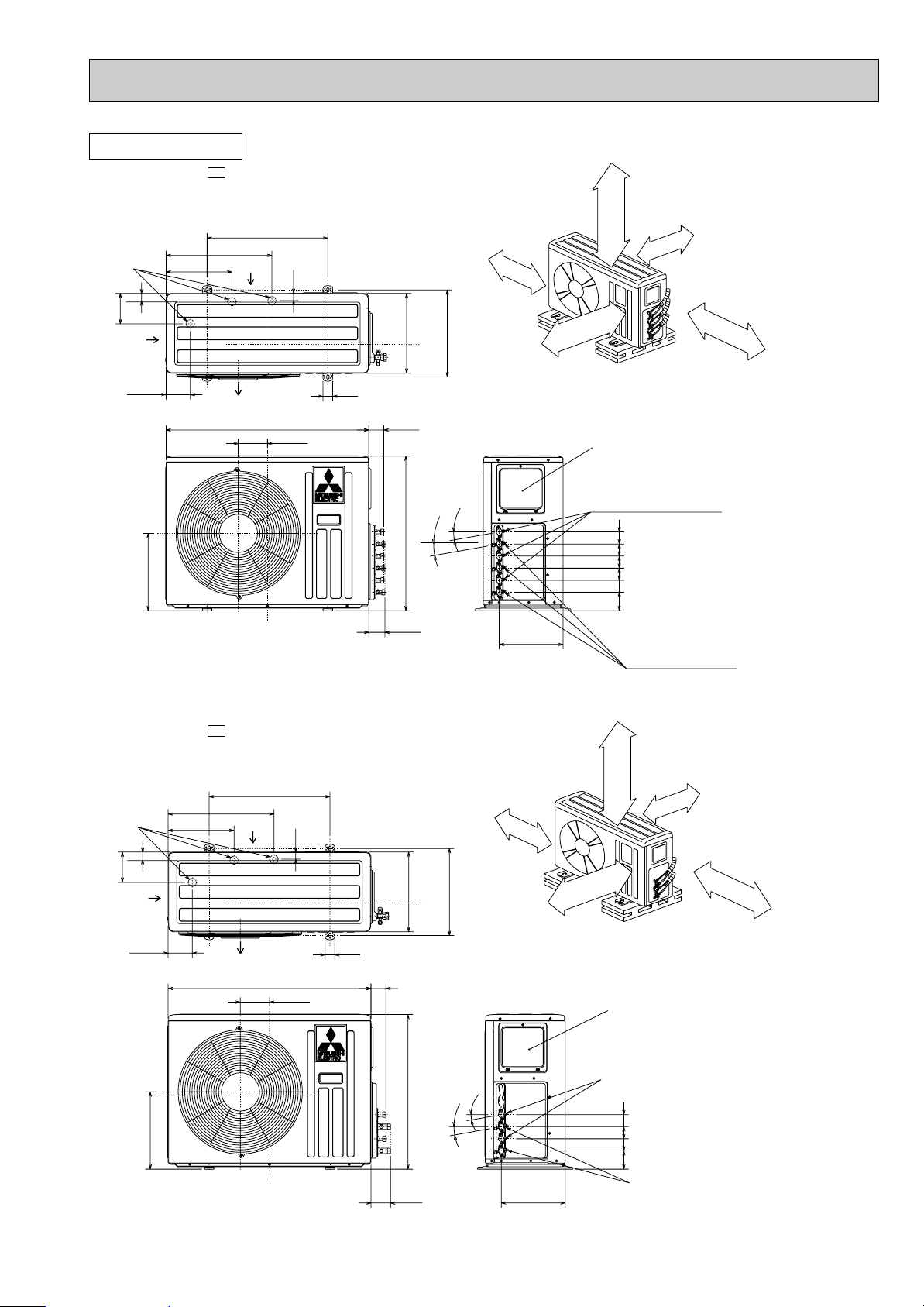
MUX-A25WV-
E1
500
840 61
264
10°
10°
Service panel
Open as a rule
500mm or more if
the front and both
sides are open
100mm or more
200mm or more if
there are obstacles
to both sides
Open as a rule
500mm or more if the back,
both sides and top are open
350mm or more
100mm or more
B UNIT
A UNIT
Gas refrigerant
pipe joint
Refrigerant pipe
(flared) {12.7
Liquid refrigerant
pipe joint
Refrigerant pipe
(flared) {6.35
80
121
40
438
Air in
Air out
Air in
273
100
125
320
30
330
640
360
76
505050
Drainage
3holes {33
}
}
34
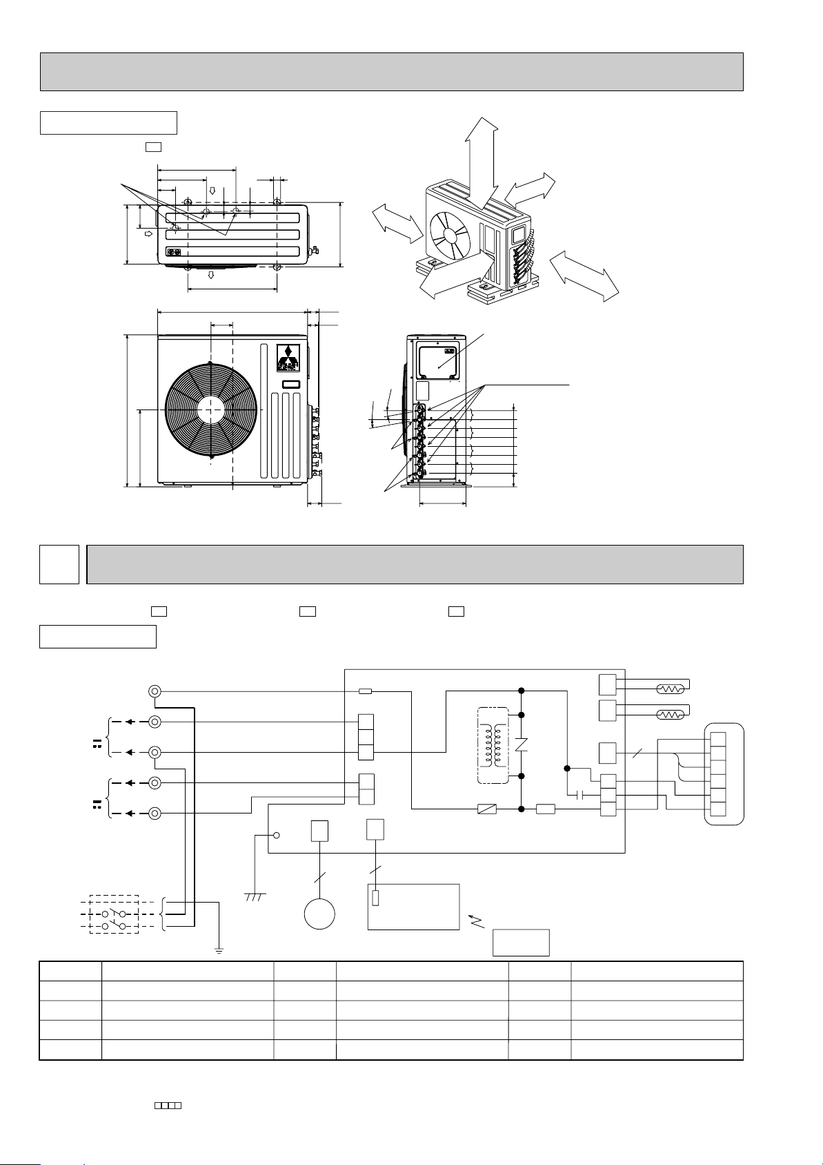
WIRING DIAGRAM
7
22
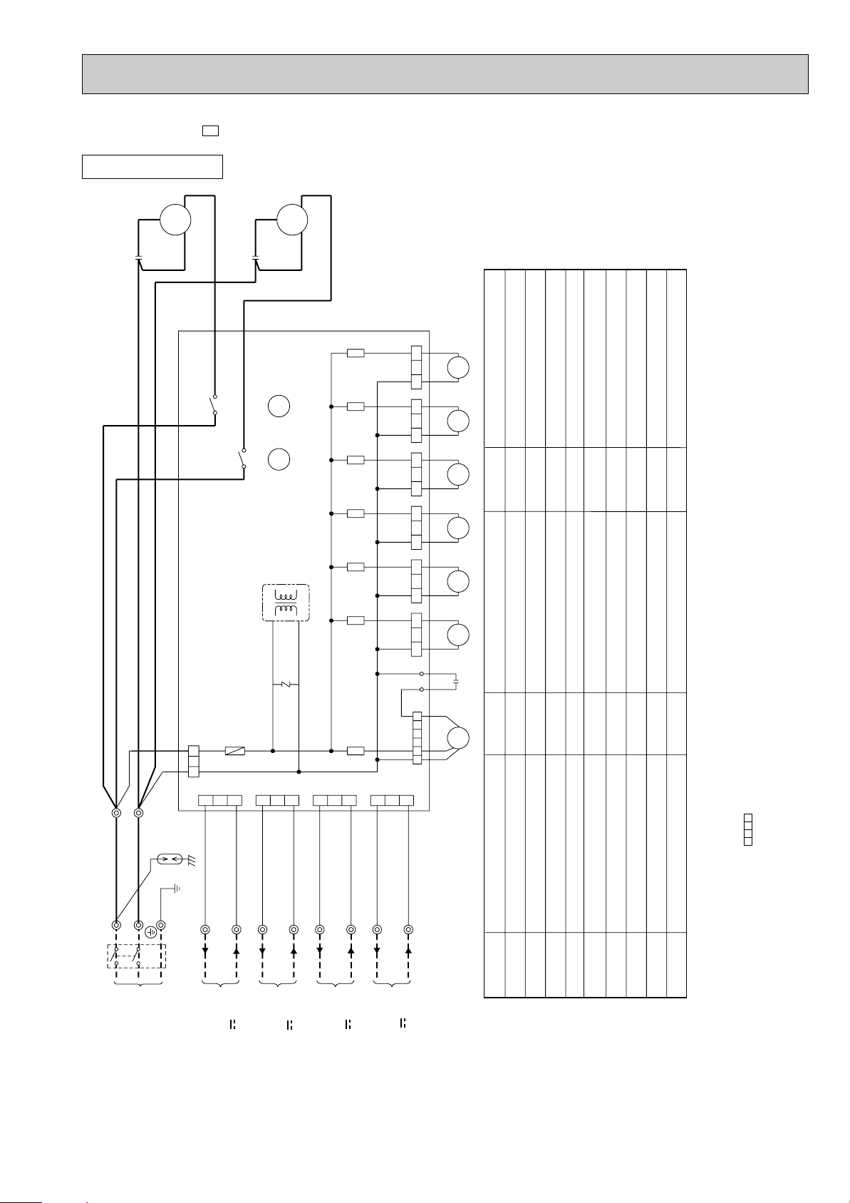
MSC-A07WV - MSC-A09WV - MSC-A12WV -
E1E1E1
MODELS WIRING DIAGRAM
SYMBOL
NR11
RT11
RT12
SR141
NAME
NAME NAME
INDOOR FAN CAPACITOR
FUSE(3.15A)
INDOOR FAN MOTOR (INNER FUSE)
VANE MOTOR
VARISTOR
ROOM TEMPERATURE THERMIST OR
INDOOR COIL THERMISTOR
SOLID STATE RELAY
TERMINAL BLOCK
SYMBOL
C11
F11
MF
MV
SYMBOL
TB
T11
TRANSFORMER
CIRCUIT BREAKER
SR141
C11
RED
WHT
3
6
5
BRN
YLW
GRY
BLK
4
3
2
1
MF
121
CN
1
3
5
111
CN
112
CN
RT12
RT11
NR11
F11
ELECTRONIC CONTROL P.C. BOARD
CN211
TAB12
CN201
3
2
1
CN202
2
1
151
CN
5
5
BRN
RED
BLU
WHT
BLK
BLU
BRN
TB
L
3
N
2
1
12V
TO OUTDOOR
UNIT
CONNECTING
POWER
SUPPLY
CORD
~/N 230V
50Hz
GRN/YLW
POWER MONITOR,
RECEIVER
P.C.BOARD
REMOTE
CONTROLLER
MV
FOR
MUH OR
MXZ TYPE
FOR
MU OR
MUX TYPE
12V
PE
101
CN
T11
GRN
LD103
INDOOR UNIT
NOTE:1. About the outdoor side electric wiring refer to the outdoor unit electric wiring diagram for servicing.
2. Use copper conductors only. (For field wiring)
3. Symbols below indicate.
/: Terminal block, : Connector
Service panel
D Unit
C Unit
B Unit
A Unit
{33
Drainage
3 holes
Air out
Air in
Air in
125
330
500
100
273
438
40
30
360
34
430
850
840
121
80
61
65
76
50
50
50
5050
50
50
260
10°
10°
Liquid refrigerant
pipe joint
Refrigerant pipe
(flared) {6.35
Gas refrigerant
pipe joint
Refrigerant pipe
(flared) {9.52
Gas refrigerant
pipe joint
Refrigerant pipe
(flared) {12.7
Open as a rule
500mm or more if
the front and both
sides are open
100mm or more
200mm or more if
there are obstacles
to both sides
Open as a rule
500mm or more if the back,
both sides and top are open
350mm or more
100mm or more
MUX-A26WV-
E1
OUTDOOR UNIT
Unit: mm

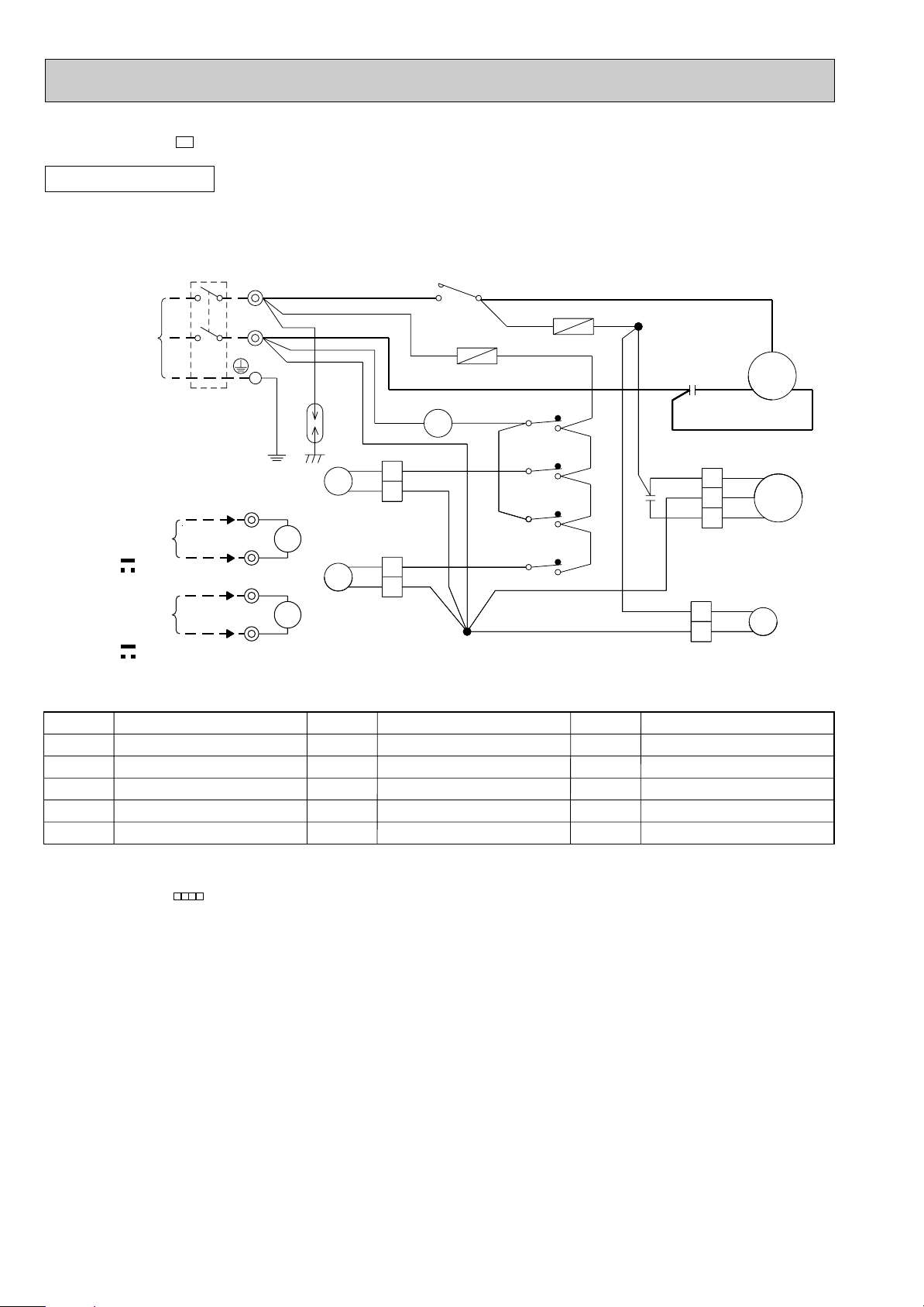
23
MODELS WIRING DIAGRAM
SYMBOL
TB1,TB2
21S4
52C
SYMBOL
MF
NR61
RT61
SR61,SR62
T61
SYMBOL
C1
C65
DSAR
F61
MC
NAME
NAME NAME
COMPRESSOR CAPACITOR
OUTDOOR FAN CAPACITOR
SURGE ABSORBER
FUSE(2A)
COMPRESSOR(INNER PROTECTOR)
OUTDOOR FAN MOTOR(INNER FUSE)
VARISTOR
DEFROST THERMISTOR
SOLID STATE RELAY
TRANSFORMER
TERMINAL BLOCK
R.V. COIL
COMPRESSOR CONTACTOR
MUH-A07WV -
MUH-A09WV -
MUH-A12WV -
E1
E1
E1
MODELS WIRING DIAGRAM
OUTDOOR UNIT
MU-A07WV -
MU-A09WV -
MU-A12WV -
E1
E1
E1
CIRCUIT BREAKER
POWER SUPPLY
~/N
230V 50Hz
12V
GRN/YLW
TB2
RED
WHT
BLK
WHT
BLU
3
2
1
RED
MF
C2
MC
C1
S
R
C
N
2
FROM
INDOOR UNIT
CONNECTING
WHT
BLU
BLK
RED
WHT
52C
TB1
WHT
BLK
52C
PE
L
1
NO
COM
DSAR
BRN
BRN
SYMBOL
52C
SYMBOL
MC
MF
TB1,TB2
SYMBOL
C1
C2
DSAR
NAME
NAME NAME
COMPRESSOR CAPACITOR
OUTDOOR FAN CAPACITOR
SURGE ABSORBER
COMPRESSOR(INNER PROTECTOR)
OUTDOOR FAN MOTOR(INNER FUSE)
TERMINAL BLOCK
COMPRESSOR CONTACTOR
MC
CN661
3
1
2
CN721
21S4
MF
SR62
SR61
TAB20
GRN/YLW
BLU
CIRCUIT BREAKER
POWER SUPPLY
BLU
BRN
DSAR
BLK
BRN
RED
DEICER P.C.BOARD
4
C1
BLK
RED
3
WHT
S
C
R
CN730
RT61
BLK
2
3
1
RED
WHT
12V
FROM
CONNECTING
INDOOR UNIT
TB2
3
N
TB1
L
N
PE
~/N
NR61
F61
T61
C65
CN711
52C
230V
50Hz
R.V.coil
heating ON
cooling OFF
OUTDOOR UNIT
NOTE:1. About the indoor side electric wiring refer to the indoor unit electric wiring diagram for servicing.
2. Use copper conductors only. (For field wiring)
3. Symbols below indicate.
/: Terminal block, : Connector
NOTE:1. About the indoor side electric wiring refer to the indoor unit electric wiring diagram for servicing.
2. Use copper conductors only. (For field wiring)
3. Symbols below indicate.
/: Terminal block, : Connector
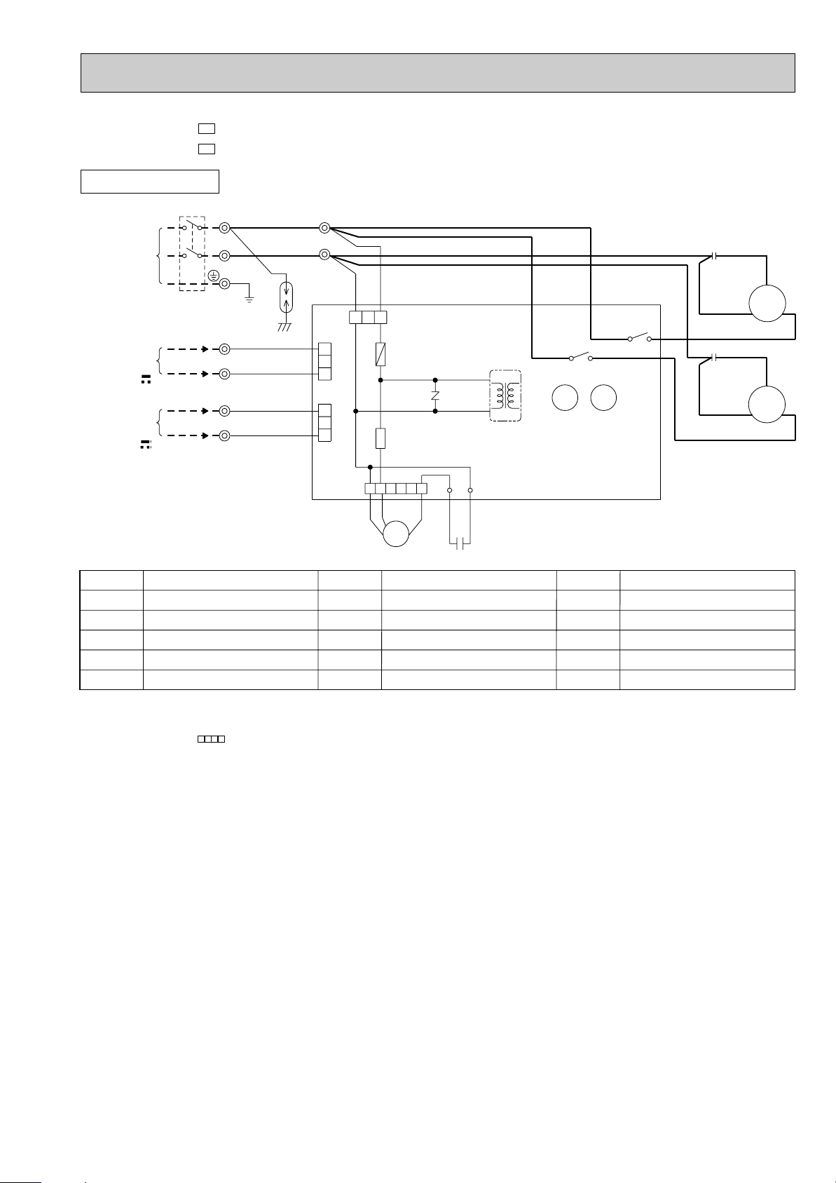
24
OUTDOOR UNIT
PE
BLU
BRN
F62
DSAR
CIRCUIT BREAKER
WHT
1
2
TB3
1
BLK
RED
C2
2
1
4
3
X1
X1
X2
X2
4
3
BLU
BRN BRN BRN
F61
BRN
BRN
WHT
WHT
WHT
WHT
BRN
52C
NO
52C
COM
3
1
RED
BLU
RED
BLK
21R
TB2
MF
WHT
2
WHT
5
5
6
6
R
S
MC
C
X2
N
L
POWER SUPPLY
~ / N
230V
50Hz
TB1
BLK
8
8
7
7
WHT
ORN
YLW
FROM INDOOR
UNIT No.A
CONNECTING
12V
X1
1
2
1
1
2
2
FROM INDOOR
UNIT No.B
CONNECTING
12V
2
TB3
C1
BLU
BLU
BLU
1
2
BLU
BLU
BLU
1
2
BLU
BLU
BLU
BLU
BLU
1
2
21R2
21R1
BLU
BLU
BLU
SYMBOL
21R1
21R2
52C
SYMBOL
MF
TB1,TB2,TB3
X1
X2
21R
SYMBOL
C1
C2
DSAR
F61,F62
MC
NAME
NAME NAME
COMPRESSOR CAPACITOR
OUTDOOR FAN CAPACITOR
SURGE ABSORBER
FUSE(2A)
COMPRESSOR(INNER PROTECTOR)
OUTDOOR FAN MOTOR(INNER FUSE)
TERMINAL BLOCK
RELAY(A)
RELAY(B)
SOLENOID COIL
SOLENOID COIL(A)
SOLENOID COIL(B)
COMPRESSOR CONTACTOR
NOTE:1. About the indoor side electric wiring refer to the indoor unit electric wiring diagram for servicing.
2. Use copper conductors only. (For field wiring)
3. Symbols below indicate.
/: Terminal block, : Connector
MUX-A10WV -
E1
MODEL WIRING DIAGRAM
25
1
2
3
123
2
1
3
RED
RED
NR61
T61
1
2
4
3
4
3
C61
LD1
WHT
WHT
OUTDOOR CONTROL
P.C. BOARD
BRN
BLU
BRN
BLU
BRN
X522
X521
BLK
SR861
LD2
RED
BLK
WHT
6
52341
BRN
BLU
BLU
TB4
CN90
TB2
X521X522
F61
CN73
CN71
FROM INDOOR
UNIT B
CONNECTING
12V
PE
CIRCUIT BREAKER
GRN/YLW
ORN
CN91
BLU
YLW
BLU
RED
RED
FROM INDOOR
UNIT A
CONNECTING
12V
1
2
C2
C1
RC
S
C
R
S
MC2
MF61
MC1
BLK
TB1
POWER SUPPLY
~/N
230V
50Hz
1
2
L
N
DSAR
BRN
OUTDOOR UNIT
SYMBOL
TB1
TB2~TB4
T61
X521
X522
SYMBOL
MC1
MC2
MF61
NR61
SR861
SYMBOL
C1
C2
C61
DSAR
F61
NAME
NAME NAME
COMPRESSOR CAPACITOR(MC1)
COMPRESSOR CAPACITOR(MC2)
OUTDOOR FAN CAPACITOR
SURGE ABSORBER
FUSE(3.15A)
COMPRESSOR(INNER PROTECTOR)
COMPRESSOR(INNER PROTECTOR)
OUTDOOR FAN MOTOR (INNER PROTECTOR)
SURGE ABSORBER
OUTDOOR FAN RELAY
TERMINAL BLOCK
TERMINAL BLOCK
TRANSFORMER
COMPRESSOR CONTACTOR(MC1)
COMPRESSOR CONTACTOR(MC2)
NOTE:1. About the indoor side electric wiring refer to the indoor unit electric wiring diagram for servicing.
2. Use copper conductors only. (For field wiring)
3. Symbols below indicate.
/: Terminal block, : Connector
MUX-A19WV -
MUX-A25WV -
E1
E1
MODELS WIRING DIAGRAM
26
1
2
3
1
2
3
123
2
1
3
123123123
21R421R3
NR61
T61
1
2
43
43
C61
LD1
WHT
WHT
OUTDOOR CONTROL P.C. BOARD
BRN
BLU
BRN
BLU
BRN
BLU
BLU
X522
X521
BLK
SR865
SR866
SR863
SR861
LD2
RED
RED
RED
BLK
WHT
652341
BRN
BLU
BLU
TB4
CN86
CN85
CN81
CN91
CN90
TB3
TB2
X521
BLU
BLU
X522
BLU
BLU
21RB
F61
CN74
CN73
CN71
FROM INDOOR
UNIT B
CONNECTING
12V
PE
CIRCUIT BREAKER
GRN/YLW
WHT
BLU
ORN
BLU
YLW
BLU
RED
RED
FROM INDOOR
UNIT A
CONNECTING
12V
1
2
1
2
C2
C1
RC
S
CR
S
MC2
FROM INDOOR
UNIT C
CONNECTING
12V
MF61
MC1
BLK
TB1
POWER SUPPLY
~/N
230V
50Hz
1
2
L
N
DSAR
BRN
OUTDOOR UNIT
SYMBOL
MF61
NR61
SR861
SR863
SR865
SR866
TB1
SYMBOL
C1
C2
C61
DSAR
F61
MC1
MC2
NAME
NAME NAME
COMPRESSOR CAPACITOR(MC1)
COMPRESSOR CAPACITOR(MC2)
OUTDOOR FAN CAPACITOR
SURGE ABSORBER
FUSE(3.15A)
COMPRESSOR(INNER PROTECTOR)
COMPRESSOR(INNER PROTECTOR)
OUTDOOR FAN MOTOR(INNER PROTECTOR)
SURGE ABSORBER
OUTDOOR FAN RELAY
RELAY (21RB)
RELAY (C) (21R4)
RELAY (B) (21R3)
TERMINAL BLOCK
TERMINAL BLOCK
TRANSFORMER
COMPRESSOR CONTACTOR(MC1)
COMPRESSOR CONTACTOR(MC2)
SOLENOID COIL
SOLENOID COIL (B)
SOLENOID COIL (C)
SYMBOL
TB2~TB4
T61
X521
X522
21RB
21R3
21R4
NOTE:1. About the indoor side electric wiring refer to the indoor unit electric wiring diagram for servicing.
2. Use copper conductors only. (For field wiring)
3. Symbols below indicate.
/: Terminal block, : Connector
MUX-A20WV -
E1
MODEL WIRING DIAGRAM
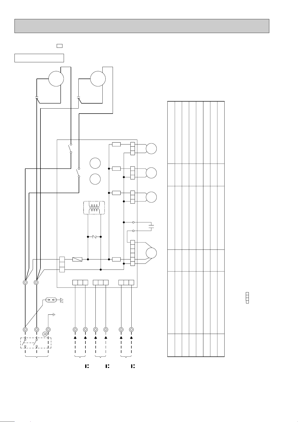
27
DSAR
CIRCUIT BREAKER
L
N
2
1
2
1
1
2
1
2
BLK
RED
MF61
21R1
BLU
BLU
RED
RED
OUTDOOR CONTROL P.C. BOARD
T61
34
43
X521
X522
MC1
S
RC
MC2
S
RC
C1
C2
BLK
RED
WHT
RED
BLK
WHT
X522 X521
13
3
1
3
1
1
3
1
3
621
CONNECTING
FROM INDOOR
POWER SUPPLY
WHT
BLU
ORN
BLU
BRN
BLU
YLW
CN74CN73CN72CN71
TB1
TB3
TB2
2
2
2
2
2
BRN
BLU
TB4
2
1
BLU
F61
BRN
BLU
SR861
CN91
435
SR868
BLU
BLU
BRN
BRN
LD1
LD2
C61
NR61
CN90
WHT
123 123
21R2
BLU
BLU
SR867
21R3
BLU
BLU
SR866
123
BLU
BLU
21R4
123
SR865
BLU
BLU
21RA
123
SR864
BLU
BLU
21RB
123
SR863
CN83 CN84 CN85 CN86 CN81CN82
~/N
12V
230V
50Hz
UNIT C
FROM INDOOR
CONNECTING
12V
UNIT A
PE
GRN/YLW
FROM INDOOR
CONNECTING
UNIT D
12V
CONNECTING
FROM INDOOR
12V
UNIT B
BRN
SYMBOL
SR861
SR863
SR864
SR865
SR866
SR867
SR868
TB1~TB4
T61
SYMBOL
C1
C2
C61
DSAR
F61
MC1
MC2
MF61
NR61
NAME
NAME NAME
COMPRESSOR CAPACITOR(MC1)
COMPRESSOR CAPACITOR(MC2)
OUTDOOR FAN CAPACITOR
SURGE ABSORBER
FUSE(3.15A)
COMPRESSOR(INNER PROTECTOR)
COMPRESSOR(INNER PROTECTOR)
OUTDOOR FAN MOTOR(INNER PROTECTOR)
SURGE ABSORBER
OUTDOOR FAN RELAY
RELAY (21RB)
RELAY (21RA)
RELAY (D) (21R4)
RELAY (C) (21R3)
RELAY (B) (21R2)
RELAY (A) (21R1)
TERMINAL BLOCK
TRANSFORMER
COMPRESSOR CONTACTOR(MC1)
COMPRESSOR CONTACTOR(MC2)
SOLENOID COIL (BALANCE)
SOLENOID COIL (BALANCE)
SOLENOID COIL (A)
SOLENOID COIL (B)
SOLENOID COIL (C)
SOLENOID COIL (D)
SYMBOL
X521
X522
21RA
21RB
21R1
21R2
21R3
21R4
NOTE:1. About the indoor side electric wiring refer to the indoor unit electric wiring diagram for servicing.
2. Use copper conductors only. (For field wiring)
3. Symbols below indicate.
/: Terminal block, : Connector
OUTDOOR UNIT
MUX-A26WV -
E1
MODEL WIRING DIAGRAM
REFRIGERANT SYSTEM DIAGRAM
28
8
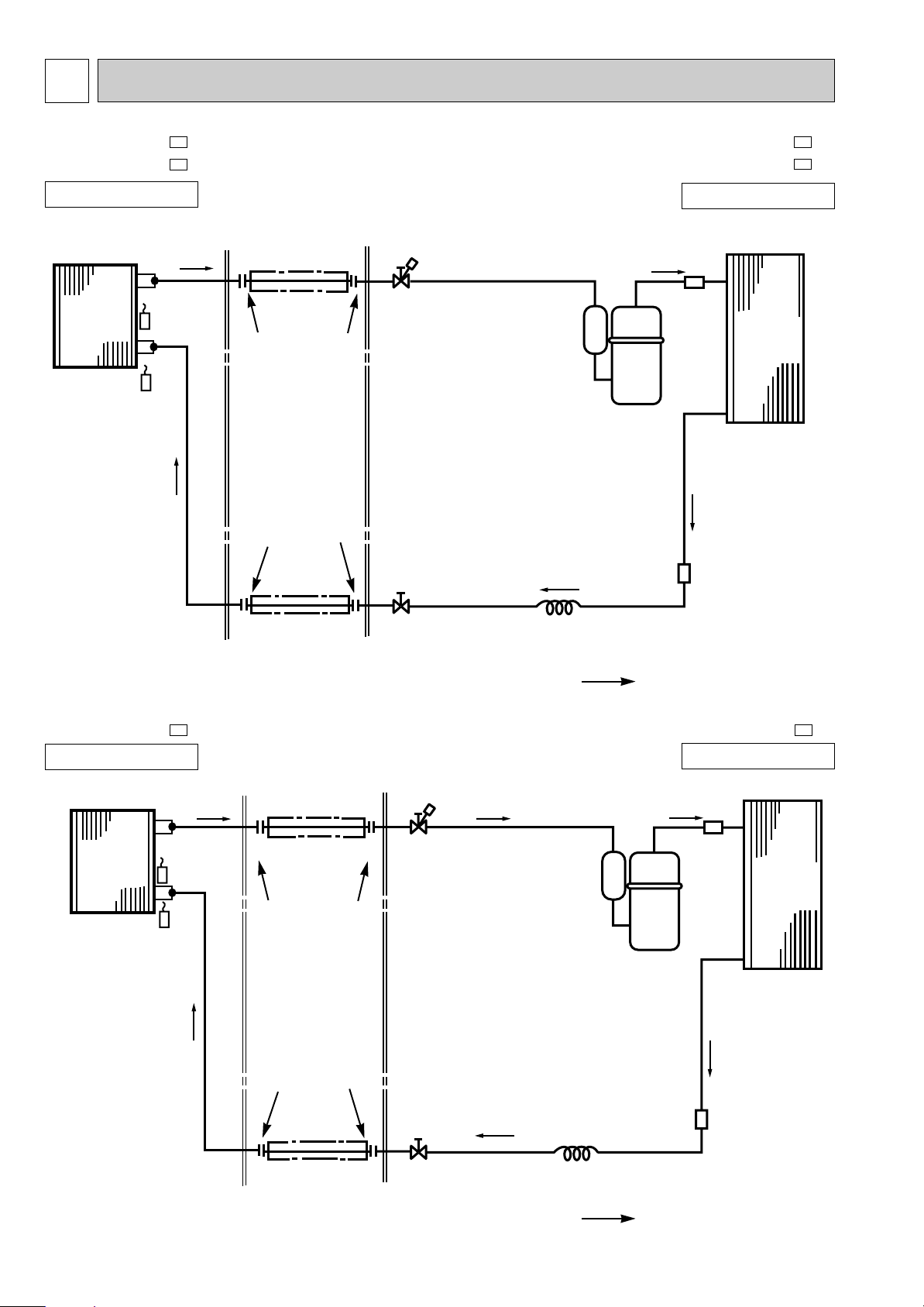
MSC-A07WV -
MSC-A09WV -
E1
E1
MU-A07WV -
MU-A09WV -
E1
E1
MSC-A12WV -
E1
MU-A12WV -
E1
INDOOR UNIT
INDOOR UNIT
OUTDOOR UNIT
OUTDOOR UNIT
Indoor
heat
exchanger
Room temperature
thermistor
RT11
Refrigerant pipe [9.52
(with heat insulator)
Outdoor
heat
exchanger
Capillary tube
[3.0x[1.4x500(MU-A07WV)
[3.0x[1.4x700(MU-A09WV)
Strainer
Refrigerant pipe [6.35
(with heat insulator)
Refrigerant flow in cooling
Unit:mm
Unit:mm
Refrigerant pipe [12.7
(with heat insulator)
Stop valve
(with service port)
Stop valve
(with service port)
Strainer
Refrigerant pipe [6.35
(with heat insulator)
Stop valve
Capillary tube
[3.0x[1.4x550
Refrigerant flow in cooling
Outdoor
heat
exchanger
Room temperature
thermistor
RT11
Indoor coil
thermistor
RT12
Indoor coil
thermistor
RT12
Compressor
Indoor
heat
exchanger
Compressor
Flared connection
Flared connection
Flared connection
Flared connection
Muffler
Muffler
29
Unit:mm
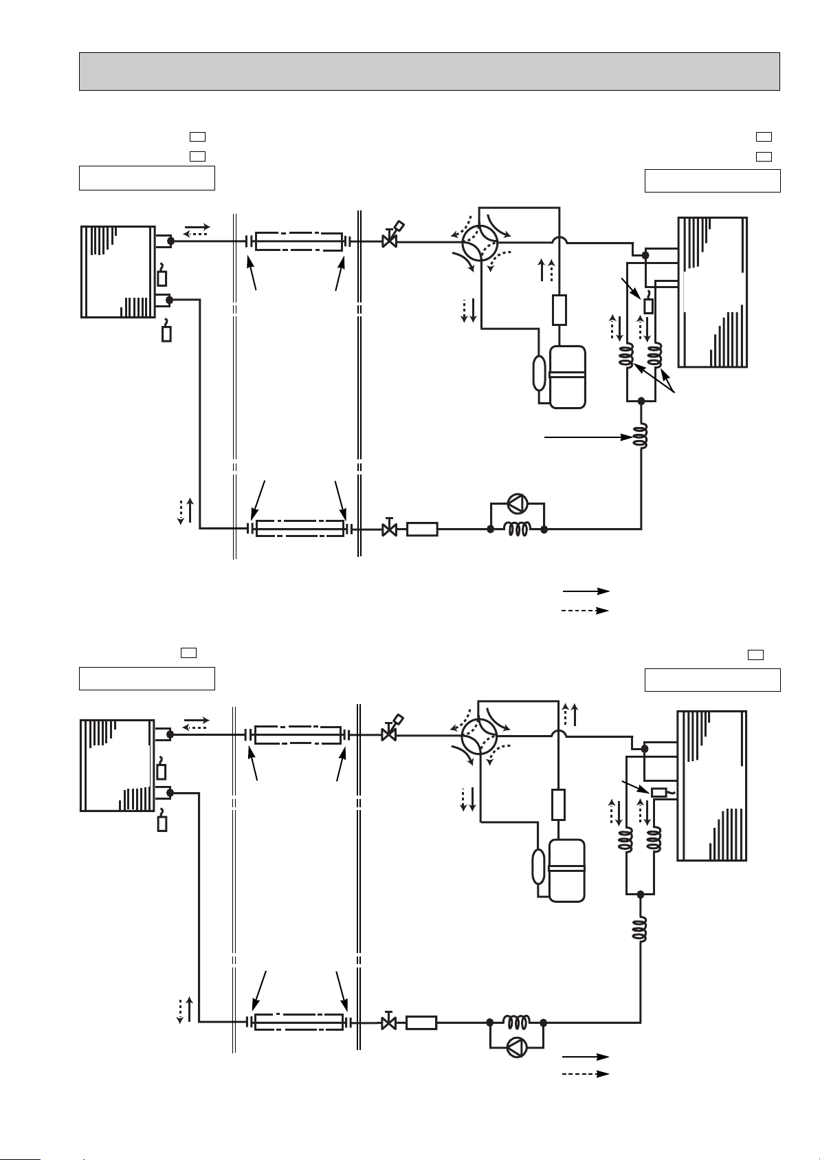
MSC-A12WV -
E1
MUH-A12WV -
E1
INDOOR UNIT
OUTDOOR UNIT
(with heat insulator)
(with heat insulator)
Refrigerant pipe [12.7
4-way valve
Stop valve
(with service port)
Strainer
Refrigerant pipe [6.35
Stop valve
Capillary tube
[3.0x[1.6x1350
Check
valve
Refrigerant flow in cooling
Refrigerant flow in heating
Defrost
thermistor
RT61
Outdoor
heat
exchanger
Room temperature
thermistor
RT11
Indoor coil
thermistor
RT12
Capillary tube
[3.0x[1.6x400
Flared connection
Flared connection
Compressor
Indoor
heat
exchanger
R.V. coil
heating ON
cooling OFF
MSC-A07WV -
MSC-A09WV -
E1
E1
MUH-A07WV -
MUH-A09WV -
E1
E1
INDOOR UNIT
OUTDOOR UNIT
Indoor
heat
exchanger
Room temperature
thermistor
RT11
(with heat insulator)
Refrigerant pipe [ 9.52
4-way valve
Defrost
thermistor
RT61
Muffler
Outdoor
heat
exchanger
Capillary tube
[3.0x[1.4x800(2 pcs)
(MUH-A07WV)
[3.0x[1.4x500(2 pcs)
(MUH-A09WV)
Capillary tube
[3.0x[1.6x350(MUH-A07WV)
[3.0x[1.6x600(MUH-A09WV)
Capillary tube
[3.0x[1.4x1050(MUH-A07WV)
[3.0x[1.4x1300(MUH-A09WV)
Check valve
Strainer
Refrigerant pipe [6.35
(with heat insulator)
Refrigerant flow in cooling
Refrigerant flow in heating
Unit:mm
Stop valve
(with service
port)
Indoor coil
thermistor
RT12
R.V. coil
heating ON
cooling OFF
Capillary tube
[3.0x[1.4x500(2pcs)
Flared connection
Flared connection
Compressor
Stop valve
Muffler
30
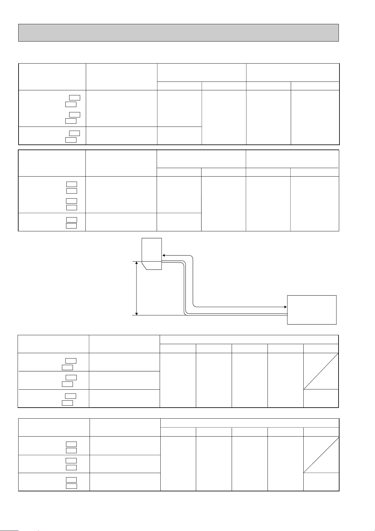
Piping size O.D : mm Length of connecting pipe : m
Model
Piping size O.D : mm Length of connecting pipe : m
Model
Refrigerant piping
Max. length : m
A
20
25
Indoor unit
Gas 0.43
Liquid 0.5
Gas
9.52
12.7
Liquid
6.35
Outdoor unit
Gas 0
Liquid 0
MSC-A07WV - E1
MUH-A07WV - E1
MSC-A09WV - E1
MUH-A09WV - E1
MSC-A12WV - E1
MUH-A12WV - E1
{
{
{
Refrigerant piping
Max. length : m
A
20
25
Indoor unit
Gas 0.43
Liquid 0.5
Gas
9.52
12.7
Liquid
6.35
Outdoor unit
Gas 0
Liquid 0
MSC-A07WV - E1
MU-A07WV - E1
MSC-A09WV - E1
MU-A09WV - E1
MSC-A12WV - E1
MU-A12WV - E1
{
{
{
Indoor
unit
w Max. Height
difference 10m
Height difference should be within
10m regardless of which unit,
indoor or outdoor position is high.
Outdoor unit
Refrigerant Piping
Max.length
A
Model
Refrigerant piping length (one way)
Model
Refrigerant piping length (one way)
7m
0
10m
60
15m
160
20m
260
MSC-A07WV - E1
MUH-A07WV - E1
MSC-A09WV - E1
MUH-A09WV - E1
MSC-A12WV - E1
MUH-A12WV - E1
{
{
{
Calculation : Xg=20g/m 5 x(A-7)m
Outdoor unit precharged
750
800
830
25m
360
25m
360
7m
0
10m
60
15m
160
20m
260
MSC-A07WV - E1
MU-A07WV - E1
MSC-A09WV - E1
MU-A09WV - E1
MSC-A12WV - E1
MU-A12WV - E1
{
{
{
Calculation : Xg=20g/m x(A-7)m
Outdoor unit precharged
750
1100
1150
MAX. HEIGHT DIFFERENCE
ADDITIONAL REFRIGERANT CHARGE(R410A : g)
MAX. REFRIGERANT PIPING LENGTH
 Loading...