


<ORIGINAL> en WT09015X01
CITY MULTI Control System
and Mitsubishi Mr. SLIM Air Conditioners
MA Remote Controller
PAR-40MAA
Installation Manual
For distribution to dealers and contractors
This installation manual describes how to install the MA Remote Controller for use with Mitsubishi Building Air Conditioning System, direct expansion type CITY MULTI air conditioner indoor units (“-A” type and later), and Mitsubishi Mr. SLIM packaged air conditioners.
Be sure to read the Simple Manual, Installation Manual, and the Instruction Book before proceeding with the installation. Failure to follow the instructions may result in equipment damage.
For information on how to wire and install the air conditioning units, refer to the installation manual.
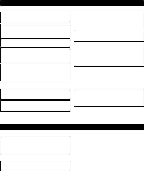
 1 Safety Precautions
•Thoroughly read the following safety precautions prior to installation.
•Observe these precautions carefully to ensure safety.
 WARNING Indicates a risk of death or serious injury.
 CAUTION Indicates a risk of serious injury or structural damage.
•After reading this manual, pass it on to the end user to retain for future reference.
•Keep this manual for future reference and refer to it as necessary. This manual should be made available to those who repair or relocate the controller. Make sure that the manual is forwarded to future end users.
All electric work must be performed by qualified personnel.
– 1 –

General precautions
 WARNING
Do not install the unit in a place where large amounts of oil, steam, organic solvents, or corrosive gases, such as sulfuric gas, are present or where acidic/alkaline solutions or sprays are used frequently. These substances can compromise the performance of the unit or cause certain components of the unit to corrode, which can result in electric shock, malfunctions, smoke, or fire.
To reduce the risk of shorting, current leakage, electric shock, malfunctions, smoke, or fire, do not wash the controller with water or any other liquid.
To reduce the risk of electric shock, malfunctions, smoke or fire, do not operate the switches/buttons or touch other electrical parts with wet hands.
To reduce the risk of injury or electric shock, stop the operation and switch off the power supply before cleaning, maintaining, or inspecting the controller.
To reduce the risk of injury or electric shock, before spraying a chemical around the controller, stop the operation and cover the controller.
To reduce the risk of injury, keep children away while installing, inspecting, or repairing the unit.
Properly install all required covers to keep moisture and dust out of the controller. Dust accumulation and water can cause electric shock, smoke, or fire.
 CAUTION
To reduce the risk of damage to the controller, do not directly spray insecticide or other flammable sprays on the controller.
To reduce the risk of injury and electric shock, avoid contact with sharp edges of certain parts.
To reduce the risk of injury, wear protective gear when working on the controller.
Consult your dealer for the proper disposal of the controller.
To avoid injury from broken glass, do not apply excessive force on the glass parts.
To reduce the risk of fire or explosion, do not place flammable materials or use flammable sprays around the controller.
Precautions during installation
 WARNING
Do not install the unit where there is a risk of leaking flammable gas.
If flammable gas accumulates around the unit, it may ignite and cause a fire or explosion.
Take appropriate safety measures against earthquakes to prevent the controller from causing injury.
Properly dispose of the packing materials. Plastic bags pose suffocation hazard to children.
To prevent injury, install the controller on a flat surface strong enough to support its weight.
 CAUTION
To reduce the risk of shorting, current leakage, electric shock, malfunctions, smoke, or fire, do not install the controller in a place exposed to water or in a condensing environment.
Controller must be installed by qualified personnel according to the instructions detailed in the Installation Manual.
Improper installation may result in electric shock or fire.
Install the top case into the bottom case until it clicks.
When attaching the cover and the top casing to the bottom casing, push it until it they click into place. If they are not properly locked into place, they may fall, causing personal injury, controller damage, or malfunctions.
– 2 –
Precautions during wiring
 WARNING
To reduce the risk of damage to the controller, malfunctions, smoke, or fire, do not connect the power cable to the signal terminal block.
Properly secure the cables in place and provide adequate slack in the cables so as not to stress the terminals. Improperly connected cables may break, overheat, and cause smoke or fire.
To reduce the risk of injury or electric shock, switch off the main power before performing electrical work.
All electric work must be performed by a qualified electrician according to the local regulations, standards, and the instructions detailed in the Installation Manual.
To reduce the risk of electric shock, install a breaker and a residual current circuit breaker on the power supply.
To reduce the risk of electric shock, smoke, or fire, install a breaker for each controller.
Use properly rated breakers and fuses (breaker, local switch <switch + fuse>, no-fuse breaker).
Breaker with a breaking capacity greater than the specified capacity may cause electric shock, malfunctions, smoke, or fire.
To reduce the risk of current leakage, overheating, smoke, or fire, use properly rated cables with adequate current carrying capacity.
Proper grounding must be provided by a licensed electrician.
Do not connect the grounding wire to a gas pipe, water pipe, lightning rod, or telephone wire.
Improper grounding may result in electric shock, smoke, fire, or malfunction due to electrical noise interference.
 CAUTION
To reduce the risk of electric shock, shorting, or malfunctions, keep wire pieces and sheath shavings out of the terminal block.
To reduce the risk of shorting, current leakage, electric shock, or malfunctions, keep the cables out of contact with controller edges.
Securely seal the cable access holes with putty to prevent condensation, water, and insects from entering and causing electric shock, malfunctions, or fire. Water infiltration and condensation formed inside the unit may damage the circuit board.
Precautions for moving or repairing the controller
 WARNING
The controller should be repaired or moved only by qualified personnel.
Do not disassemble or modify the controller. Improper installation or repair may cause injury, electric shock, or fire.
 CAUTION
To reduce the risk of electric shock, shorting, or malfunctions, keep wire pieces and sheath shavings out of the terminal block.
– 3 –

Additional precautions
To avoid damage to the unit, use appropriate tools to install, inspect, or repair the unit.
This controller is designed for exclusive use with the Building Management System by Mitsubishi Electric. The use of this controller for with other systems or for other purposes may cause malfunctions.
To avoid discoloration, do not use benzene, thinner, or chemical rag to clean the controller. To clean the controller, wipe with a soft cloth soaked in mild detergent that is diluted with an appropriate amount of water, and wipe down with a wet cloth followed by a dry cloth. Do not use the detergent straight.
To avoid damage to the controller, provide protection against static electricity.
Take appropriate measures against electrical noise interference when installing the air conditioners in hospitals or facilities with radio communication capabilities.
Inverter, high-frequency medical, or wireless communication equipment as well as power generators may cause the air conditioning system to malfunction. Air conditioning system may also adversely affect the operation of these types of equipment by creating electrical noise.
To avoid malfunctions, do not bundle power cables and signal cables together, or place them in the same metallic conduit.
Leave the circuit board and its protective film on the case.
To avoid damage to the controller, do not overtighten the screws.
Use a flat-head screwdriver with a blade width of 3-5 mm (1/8-7/32 inch).
Do not turn the flat-head screwdriver with fitting it in the latch strongly.
To avoid deformation and malfunction, do not install the remote controller in direct sunlight or where the ambient temperature may exceed 40ºC (104ºF) or drop below 0ºC (32ºF).
Do not install the controller on the control panel door. Vibrations or shocks to the controller may damage the controller or cause the controller to fall.
Secure the cable with a clamp.
Do not use solderless terminals to connect cables to the terminal block.
Solderless terminals may come in contact with the circuit board and cause malfunctions or damage the controller cover.
After connecting the connector, install the top case properly.
If the supply cord is damaged, it must be replaced by the manufacturer, its service agent or similarly qualified persons in order to avoid a hazard.
This appliance is not intended for use by persons (including children) with reduced physical, sensory or mental capabilities, or lack of experience and knowledge, unless they have been given supervision or instruction concerning use of the appliance by a person responsible for their safety.
Children should be supervised to ensure that they do not play with the appliance.
This appliance is intended to be used by expert or trained users in shops, in light industry and on farms, or for commercial use by lay persons.
To avoid damage to the controller, use appropriate tools to install, inspect, or repair the controller.
To prevent malfunctions, do not remove the protective film or the circuit board from the casing.
Do not install the controller on the control panel door. Vibrations or shocks to the controller may damage the controller or cause the controller to fall.
To avoid damage to the controller, do not make holes on the controller cover.
Hold the cables in place with clamps to prevent undue force from being applied to the terminal block and causing cable breakage.
– 4 –
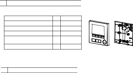
 2 Component names and supplied parts
The following parts are included in the box.
Parts name |
Qty. |
Appearance |
Top case *1 |
Bottom case *2 |
|
|
|||
Remote controller (top case) |
1 |
Right figure *1 |
|
|
Remote controller (bottom case) |
1 |
Right figure *2 |
|
|
Roundhead cross slot screws M4×30 |
2 |
*3 |
|
|
Wood screw 4.1×16 |
2 |
*3 |
|
|
(for direct wall installation) |
|
|
||
|
|
|
|
|
Simple Manual |
1 |
|
|
|
*3 ISO metric screw thread
*4 Remote controller cable is not included.
 3 Field-supplied parts/Required tools
(1) Field-supplied parts
The following parts are field-supplied parts.
Parts name |
Qty. |
Notes |
|
|
|
Double switch box or 86type |
1 |
Not required for direct wall installation |
switch box |
|
|
Thin metal conduit |
Necessary |
|
|
|
|
Lock nut and bushing |
Necessary |
|
|
|
|
Cable cover |
Necessary |
Required for routing remote controller cable along a wall |
|
|
|
Putty |
Reasonable |
|
|
|
|
Molly anchor |
Necessary |
|
|
|
|
Remote controller cable |
Necessary |
|
(Use a 0.3 mm² (AWG22) 2-core |
|
|
sheathed cable.) |
|
|
(2)Field-supplied tools
•Flat-tip screwdriver (Width: 3 - 5 mm (1/8 - 7/32 inch))
•Nipper
•Miscellaneous tools
– 5 –

 4 How To Wire Transmission Line
The wiring is different when the remote controller is connected to a CITY MULTI control system (“-A” type and later) and when it is connected to a Mr. SLIM air conditioner (A control type). The wiring also differs with the system configuration. Check the system used.
1. Connecting to CITY MULTI control system
The numbers (1) to (4) in the figure correspond to items (1) to (4) in the following description.
Address = 51 |
Group 01 |
|
Group 02 |
|
Group 03 |
|
|
Connect to TB15 |
||
|
a |
Address = 01 |
Address = 02 |
Address = 03 |
Address = 04 |
|
on the indoor unit. |
|||
TB7 |
TB3 |
Address = 09 |
||||||||
|
|
|
|
|
|
|
|
|
|
(4) |
|
|
b |
|
b |
|
b |
|
b |
|
c |
|
|
TB5 TB15 |
TB5 |
TB15 |
TB5 |
TB15 |
TB5 |
TB15 |
TB5 |
TB15 |
|
|
(1) |
(1) |
(1) |
|
|
|
|
|
|
|
|
|
|
|
|
|
|
|
|
(2) |
|
|
d |
|
d |
e |
d |
|
(2) |
|
|
Address = 55 |
(3) |
|
(3) |
|
(3) |
|
|
|
a Outdoor unit |
|
|
|
|
|
|
|
|
|
|
|
|
|
a |
Address = 08 |
|
|
Address = 06 |
Address = 05 |
|
b Indoor unit |
||
TB7 |
TB3 |
Address = 07 |
|
|||||||
|
c LOSSNAY or |
|||||||||
|
|
b |
|
b |
|
b |
|
b |
|
|
|
|
|
|
|
|
OA processing unit |
||||
f |
|
TB5 TB15 |
TB5 |
TB15 |
TB5 |
TB15 |
TB5 |
TB15 |
|
|
|
|
|
|
|
|
|
|
|
d Main Remote Controller |
|
|
|
|
|
|
|
|
|
|
|
|
|
|
(1) |
|
|
|
|
|
|
|
e Sub Remote Controller |
g |
|
|
|
|
|
|
|
|
f Central controller |
|
|
|
|
|
|
|
|
|
|
||
|
|
d |
|
e |
|
|
|
(2) |
|
g Power supply unit for |
|
|
Group 04 (3) |
|
|
|
|
|
|
|
transmission line |
|
|
|
|
|
|
|
|
|
|
|
(1)Wiring from the remote controller
•Connect to the MA remote controller terminal block (TB15) on the indoor unit.
•The terminal block has no polarity. Connect to the terminal block at the bottom of the remote controller case.
(2)Operating in a group (Groups 03, and 04 above)
•Interconnect the MA remote controller terminal block (TB15) of the indoor units you want to operate as a group, and connect the MA remote controller to that point.
•When the remote controller is used in combination with the system controller as shown in the figure above, group setting at the system controller (central controller in the figure above) is necessary.
(3)Number of connectable remote controllers
•A main remote controller and one sub remote controller, a total of two, can be connected to a group made up of indoor units.
(4)To interlock to a LOSSNAY or OA processing unit, make the following settings using the remote controller. (For a description of how to set an interlock, see section 10 “Service menu” (5) “LOSSNAY setting”.)
Set the LOSSNAY or OA processing unit address and the address of all the indoor units you want to interlock.
(5)Total length of remote controller wiring
•The MA Remote Controller can be wired up to 200 m (656 ft).
CAUTION |
Remote controllers cannot be wired together. Only one wire |
can be connected to the remote controller terminal block. |
|
|
|
d 
 e
e
NOTE: When interlocking the MA remote controller with a LOSSNAY or OA processing unit, always set the address of all the indoor units in the group and the address of the LOSSNAY or OA processing unit.
– 6 –

2. Connecting to Mr. SLIM air conditioner
The remote controller wiring depends on the system configuration. Check the system configuration. Wire the remote controller as shown in the example below.
The numbers (1) to (3) in the figure correspond to items (1) to (3) in the following description.
[1]Connecting the remote controller for each refrigerant system (Standard 1:1, simultaneous twin, simultaneous triple, simultaneous four)
Simultaneous twin |
Simultaneous twin |
Connect to TB5 |
||
a |
Refrigerant |
a |
Refrigerant |
on the indoor unit. |
address = 00 |
address = 00 |
|
||
TB1 |
TB1 |
|
|
|
TB4 |
TB4 |
TB4 |
TB4 |
|
b |
b |
b |
b |
|
TB5 |
(1) |
TB5 |
(1) |
|
|
|
|
|
|
(3) |
|
(3) |
(3) |
|
dd e
[2]When grouping by different refrigerant systems
Standard 1:1 Simultaneous twin |
Simultaneous triple |
|
|
||||
|
Refrigerant |
|
Refrigerant |
|
Refrigerant |
|
|
a address=00 |
a address = 01 |
a address = 02 |
|
|
|||
TB1 |
(Main) |
TB1 |
(Sub) |
TB1 |
(Sub) |
|
|
|
|
|
|
a Outdoor unit |
|||
|
|
|
|
|
TB4 |
|
|
TB4 |
|
TB4 |
TB4 |
TB4 |
TB4 |
b Indoor unit |
|
b |
|
b |
b |
b |
b |
b |
|
|
d Main Remote Controller |
||||||
TB5 |
(2) |
TB5 |
(2) |
TB5 |
|
|
|
|
|
e Sub Remote Controller |
|||||
|
(1) |
|
|
|
|
|
|
|
|
|
|
|
|
|
|
(3) |
d |
|
|
|
|
|
|
|
|
|
|
|
|
|
|
*Set the refrigerant address using the outdoor unit dip switches. (For more information, refer to the outdoor unit installation manual.)
*All the indoor units enclosed in  are controlled as one group.
(1)Wiring from remote controller
•Connect to indoor unit TB5 (remote controller terminal block). (The terminal block has no polarity.)
•For simultaneous multi type, when mixing various types of indoor units, always connect the remote controller to the indoor unit with the most functions (wind velocity, vane, louver, etc.).
(2) When grouping with difference refrigerant systems
• Group using the remote controller wiring. Connect the remote controller to an arbitrary indoor unit of each refrigerant system you want to group.
• When mixing different types of indoor units in the same group, always make the outdoor unit connecting the indoor unit with the most functions (wind velocity, vane, louver, etc.) the Main unit (refrigerant address = 00). Also, when the Main unit is the simultaneous multi type, always satisfy the conditions of (1) above.
• The MA Remote Controller can control up to 16 refrigerant systems as one group.
(3) Up to two remote controllers can be connected to one group
•When only one remote controller is connected to one group, set it as the Main controller. When two remote controllers are connected to one group, set the Main remote controller and Sub remote controller. (For a description of how to set the Main/Sub setting, refer to the section on initial setting in this manual.)
– 7 –

(4) Total length of remote controller wiring
• The MA Remote Controller can be wired up to 450 m (1476 ft).
 CAUTION - The wiring cannot be connected to TB5 of the indoor unit of the same refrigerant system. If so connected, the system will not operate normally.
-Remote controllers cannot be wired together. Only one wire can be connected to the remote controller terminal block.
-When connecting to TB5, connect up to two wires of the same size to one terminal block.
Simultaneous twin |
Standard 1:1 |
Simultaneous twin |
Standard 1:1 |
|
||||
|
Refrigerant |
|
Refrigerant |
|
Refrigerant |
|
Refrigerant |
|
a |
address = 00 |
a |
address = 00 a |
address = 01 |
a |
address = 00 |
|
|
|
TB1 |
TB1 |
|
TB1 |
|
TB1 |
|
|
TB4 |
TB4 |
TB4 |
|
TB4 |
TB4 |
TB4 |
|
|
b |
b |
b |
|
b |
b |
b |
|
a Outdoor unit |
TB5 |
TB5 |
TB5 |
|
TB5 |
TB5 |
TB5 |
|
|
|
|
|
|
|
|
|
|
b Indoor unit |
d |
|
d |
|
|
|
d |
e |
d Main Remote Controller |
|
|
|
|
e Sub Remote Controller |
||||
|
|
|
|
|
|
|
|
|
 5 How To Install
This remote controller is for the wall installation. It can be installed either in the switch box or directly on the wall. When performing direct wall installation, wires can be thread through either back or top of the remote controller.
(1) Selecting an installation site
Install the remote controller (switch box) on the site where the following conditions are met.
(a)For connection to the indoor unit with an Auto descending panel, a place where people can check the Auto descending panel operation of the indoor unit while they are operating the remote controller (Refer to the indoor unit Instructions Book for how to operate Auto descending panel.)
(b)A flat surface
(c)A place where the remote controller can measure the accurate indoor temperature
Sensors to monitor indoor temperature are on the indoor unit and on the remote controller. When the room temperature is monitored with the sensor on the remote controller, the built-in sensor on the remote controller monitors the room temperature. When using the sensor on the remote controller, follow the instructions below.
•To monitor the accurate indoor temperature, install the remote controller away from direct sunlight, heat sources, and the supply air outlet of the air conditioner.
•Install the remote controller in a location that allows the sensor to measure the representative room temperature.
•Install the remote controller where no wires are routed around the temperature sensor on the controller. (If wires are routed, the sensor cannot measure accurate indoor temperature.)
Important
■Discrepancy between the indoor temperature measured at the wall and the actual indoor temperature may occur.
If the following conditions are met, the use of the temperature sensor on the indoor unit is recommended.
•Supply air does not reach to the wall easily where the remote controller is installed due to improper airflow distribution.
•There is a great discrepancy between the wall temperature and the actual indoor temperature.
•The back side of the wall is directly exposed to the outside air.
Note: When temperature changes rapidly, the temperature may not be detected accurately.
– 8 –

Do not install the controller in a place where the difference between the remote controller surface temperature and the actual room temperature will be great.
If the temperature difference is too high, room temperature may not be adequately controlled.
To reduce the risk of malfunctions, do not install the controller in a place where water or oil may come into contact with the controller, or in a condensing or corrosive environments.
To avoid deformation and malfunction, do not install the remote controller in direct sunlight or where the ambient temperature may exceed 40ºC (104ºF) or drop below 0ºC (32ºF).
To reduce the risk of malfunctions and damage to the controller, avoid installing the remote controller on an electrically conductive surface, such as an unpainted metal sheet.
Refer to either of the following manuals for temperature sensor setting: indoor unit Installation Manual for CITY MULTI; this manual for Mr. SLIM.
(2) Installation space
Leave a space around the remote controller as shown in the figure shown below, regardless of whether the controller is installed in the switch box or directly on the wall. Removing the remote controller will not be easy with insufficient space.
Also, leave an operating space in front of the remote controller.
External dimensions of remote controller |
|
30 (1-3/16) |
30 |
30 |
|
|
(1-3/16) |
(1-3/16) |
Minimum required space |
|
|
around the remote |
|
|
controller |
|
|
Temperature sensor |
|
|
|
|
120 (4-3/4) |
|
|
Unit: mm (in) |
(3) Installation work
Controller can be installed either in the switch box or directly on the wall. Perform the installation properly according to the installation method.
1Drill a hole in the wall.
■Installation using a switch box
•Drill a hole in the wall, and install the switch box on the wall.
•Connect the switch box to the conduit tube.
■Direct wall installation
•Drill a hole in the wall, and thread the cable through it.
2Seal the cable access hole with putty.
■Installation using a switch box
•Seal the remote controller cable access hole at the connection of switch box and conduit tube with putty.
|
Wall |
Conduit tube |
|
|
|
|
|
Locknut |
|
|
Switch box |
Bushing |
|
Seal the gap |
|
|
with putty. |
|
Remote |
|
|
controller cable |
|
To reduce the risk of electric shock, malfunctions, or fire, seal the gap between the cables and cable access holes with putty.
– 9 –
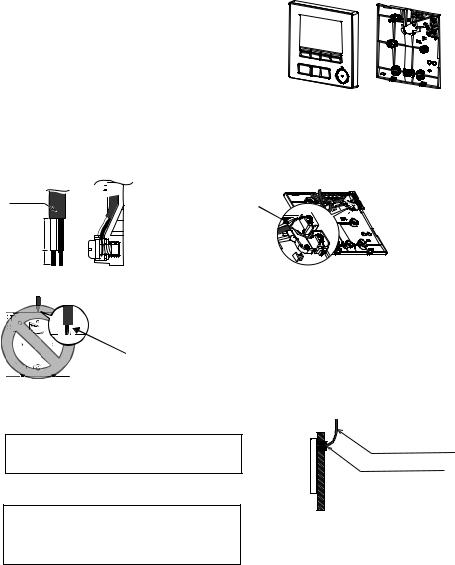
3 Prepare the bottom case of the remote controller.
Top case |
Bottom case |
4 Connect the remote controller cable to the terminal block on the bottom case.
Peel off the remote controller cable sheath as shown below to connect to the terminal block properly. Secure the remote controller cable so that the peeled part of the cable will fit into the case.
Sheath 

 Connect the cable.
(non-polarized) 


15 (19/32)
6 (1/4)
Unit: mm (in)
2-core wire must not be seen on the back.
■Direct wall installation
•Seal the hole through which the cable is threaded with putty.
To reduce the risk of electric shock, shorting, or malfunctions, keep wire pieces and sheath shavings out of the terminal block.
Important
Do not use solderless terminals to connect cables to the terminal block.
Solderless terminals may come in contact with the circuit board and cause malfunctions or damage the controller cover.
Remote controller cable
Seal the gap with putty.
Route the cable behind the remote controller.
– 10 –
 Loading...