


Service Bulletin List
No. |
Subject |
Date |
MSB-97E26-001 |
CHANGE OF FRONT ROTOR FOR ABS |
1997-12-05 |
|
EQUIPPED VEHICLES (REVICED) |
|
MSB-97E37-003 |
CHANGE IN TIE ROD NUT TIGHTENING TORQUE |
1998-01-16 |
|
VALUES |
|
MSB-97E52-001 |
ADDITION OF SRS AIR BAG MAINTENANCE |
1997-04-30 |
|
PROCEDURE |
|
MSB-98E00-011 |
CHANGE IN YEAR MODEL FOR ´99 PAJERO |
1998-10-15 |
MSB-98E27-001 |
CHANGE OF ABS REAR ROTOR |
1998-06-15 |
MSB-98E37-002 |
NEW SERVICE PROCEDURE FOR POWER |
1999-08-15 |
|
STEERING GEARBOX |
|
MSB-98E42-502 |
CORRECTING MINIMUM ENTRAPMENT AMOUNT |
1998-11-30 |
|
FOR POWER WINDOW WITH SAFETY |
|
|
MECHANISM |
|
MSB-98E54-002 |
CORRECTION TO ELC 4-SPEED AUTOMATIC |
1998-11-30 |
|
TRANSMISSION CIRCUIT |
|
MSB-99E11-502 |
CORRECTION OF 4M40 ENGINE IDLE UP SPEED |
1999-11-15 |
|
(FOR ANTI-SKID BRAKE) |
|
MSB-99E16-001 |
CHANGE OF GLOW PLUG |
2000-04-15 |
MSB-00E31-001 |
WHEEL BALANCE ADJUSTMENT PROCEDURE |
2000-07-15 |
MSB-00E35-001 |
CHANGE TO ERASING OF ABS DIAGNOSTIC |
2000-05-30 |
|
CODES |
|
MSB-00E37-501 |
ADDITION OF STEERING ANGLE ADJUSTMENT |
2000-12-30 |
|
PROCEDURE |
|

SERVICE BULLETIN
QUALITY INFORMATION ANALYSIS
OVERSEAS SERVICE DEPT. MITSUBISHI MOTORS CORPORATION
SERVICE BULLETIN |
No.: MSB-00E31-001 |
|
|
||
|
|
|
Date: 2000-07-15 |
<Model> |
<M/Y> |
Subject: |
WHEEL BALANCE ADJUSTMENT PROCEDURE |
ALL MODELS |
00-00 |
||
|
|
|
|
|
|
Group: |
WHEEL & TIRES |
Draft No.: 99AL121708 |
|
|
|
|
|
|
|
|
|
INFORMATION/ CORRECTION
INTERNATIONAL |
|
|
CAR |
|
|
ADMINISTRATIO |
T.NITTA - PROJECT LEADER |
|
OFFICE |
||
AFTER SALES SERVICE & CS PROMOTION |
1. Description:
There have been cases where the troubles failed to be removed completely because of incorrect balancer machine handling or use of an inaccurately calibrated balancer machine. This Service
Bulletin informs you of the cautions to be taken when handling a balancer machine and the balance check procedures to prevent such a case from recurring in a dealer.
2. Details:
To solve the problems caused by steering or body vibrations, it is essential to balance the wheels and tires accurately. For this, the wheel and tire must be accurately centered with respect to the balancer shaft, and the balancer must also be calibrated accurately.
Procedures
1.Check to ensure that the balancer cone and the cone-contacting portion of the wheel are free from any dirt, corrosion and damage.
2.Remove all balance weights attached, stones caught in the tire grooves and mud adhered from th wheel and tire.
3.Install the wheel and tire to the balancer in the following procedure:
Caution:
•The socket diameter of a Mitsubishi genuine wheel is ɸ 67.0 mm (2.64 in) for passenger cars and ɸ 107.5 mm (4.23 in) the other types of vehicle. Be sure to use the balancer cone matching the socket diameter.
•Use the black-mounted cone to secure the wheel to the balancer if possible. If installable i this method, go to Step 4.
•If the socket diameter of the wheel is too large to secure it with the back-mounted cone, secure the wheel to the balancer with the front mounting cone. If the wheel is to be secured in this way, go to Step 6.
•Do not use the log nut hole mounting method because it does not allow the accurat centering of the wheel.
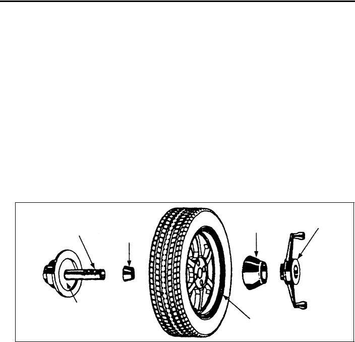
4.When securing with back-mounted cone:
Operate the balancer to measure the imbalance, an attach weight in accordance with the measurements.
Caution: Be sure to drive the weight straight in the wheel.
HUB/SHAFT |
WHEEL |
CLAMPING CUP |
WING NUT |
ASSEMBLY |
MOUNTING |
|
|
|
|
||
|
CONE |
|
|
SPRING PLATE |
|
|
|
|
|
STANDARD WHEEL |
|
|
|
RIM |
X0043BY |
5.Loosen the wing nut, rotate the wheel half a turn (180°) and tighten the nut again. Then, perform the measurement again to confirm that the wheel is in balance. If not in balance, check if the balancer is correctly calibrated. Go to Step 11.
2

6.When securing with front-mounted cone:
Caution:
•When pressing in the cone by tightening the wing nut slowly, hold the tire by hand such that the wheel may contact the spring plate of the balancer evenly.
•If this work is not performed with care, the wheel would fail to be centered correctly. Futhermore, the cone-contacting area of the wheel would deform, preventing subsequent wheel balancing from being performed accurately.
Operate the balancer to measure the imbalance. Mark the point attributable to the imbalance with a piece of chalk.
(Do not attach any balance weight.)
|
PRESSURE |
LIGHT TRUCK |
RING |
MOUNTING CONE |
WING NUT |
HUB/SHAFT-ASSEMBLY
SPRING PLATE
LIGHT TRUCK RIM
X0044BY
7.Loosen the wing nut, rotate the wheel half a turn (180°) and tighten the wing nut carefully again. Then, perform the measurement again.
8.Repeat the measurement three times in the same manner, and take either of the following measures according to the measurement again.
Caution: Be sure to drive the weight straight in the wheel.
a.If the results are the same in all measurements, attach a weight according to the indication on th machine.
b. If the weight difference among the three measurements is less than 0.5 oz and the thre indicated points are all within a range of less than 8 inch (30°), attach a weight having the average weight at the mean position.
c.If the weight difference among the three measurements is 0.5 oz or more or if the indicate
positions are not within a range of less than 8 inch (30°), check if th balancer is correctly calibrated. Go to step 11.
9.Reinstall the tire to the vehicle, and perform a driving test. If the tire still generates vibration, perform the Ste 10.
10.Attach the adapter (MB991820) on the back side of th wheel, and install the wheel onto the machine using the back-mounted cone. Then, perform the balance adjustment again. For the procedure, refer to Steps 4 and 5
Caution Check to ensure that the contactin portions of the adapter, wheel and balancer are free from any dirt, corrosion and damage.
WHEEL
MB991820
HUB/SHAFT
ASSEMBLY
WHEEL CLAMPING MOUNTING CUP
CONE
X0045BY
3

11.Checking for calibration.
Check your balancer’s calibration approximately every 100 balances. Your whee balancer’s instruction manual should include calibration procedures. If the calibration procedures specifically for your balancer are missing, use following steps for zero calibration, static balance, and dynamic balance checks. Th wheel balancer calibration checks are also described in the flowchart on next page.
a.Mount an undamaged original-equipment alloy rim and tire assembly (wheel) onto your off-the-car wheel balancer. Balance the wheel.
b.Zero Calibration Check. Loosen the balancer wing nut, rotate the wheel a half-turn (180°), and retighten the nut. Recheck the balance.
i)If the imbalance is 5 grams or less, the zero calibration is OK. Rebalance the wheel, then g to Step d to check the static balance.
ii)If the imbalance is more than 5 grams, go to Step c.
c. Loosen th balancer wing nut, rotate the wheel ¼ turn (90°), and retighten the nut. Recheck th wheel balance
i) |
If the imbalance is 5 grams or less, the wheel may not be centered on th balancer, or the |
|
balancing cones, the cup, and/or wing nut are damaged, dirty, or inappropriate for the wheel. |
|
You may need to refer to th balancer manufacturer’s instructions to verify the correct |
|
attachments. After making the necessary correction, recheck the wheel balance. If OK, then |
|
go to Step d. |
ii) |
If the imbalance is more than 5 grams, th balancer requires calibration, Contact th balancer |
|
manufacturer for calibration by their repair representative. |
d.Static Balance Check. Attach a 5-gram weight to the outer rim. Recheck the balancer. The balancer should detect 5±2 grams of imbalance 170° to190° away from the 5-gram weight.
i)If the imbalance is within specification, the static balance calibration is correct, Go to Step e to check the dynamic balance.
ii) |
If the imbalance is out of specification, th balancer requires calibration. Contact th balancer |
|
manufacturer for calibration by their repair representative. |
e. Dynamic Balance Check. Attach a 5-gram weight to the inner rim at 180° opposite the 5-gram weight that was added in Step d. Recheck the balance. Th balancer should detect 5±2 grams of imbalance 170° to 190° away from both the inner and outer 5-gram weights.
i)If the imbalance is within specification, the dynamic balance calibration is correct. Th balancer calibration checks are complete.
ii) |
If the imbalance is out of specification, th balancer requires calibration. Contact th balancer |
|
manufacturer for calibration by their repair representative. |
4
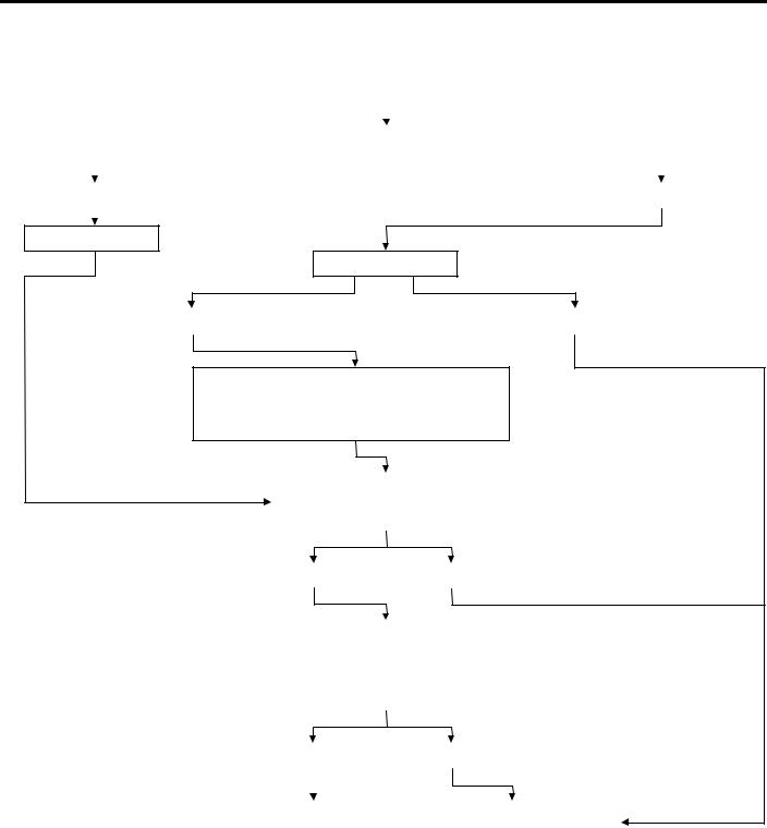
WHEEL BALANCER CALIBRATION CHECKS
|
|
|
|
Balance Wheel |
|
|
|
|
|||
|
|
|
|
|
|
|
|
|
(Zero Calibration Check) |
||
|
|
|
|
|
|
|
|||||
|
|
|
|
|
|
|
|
|
|||
|
|
|
Rotate wheel ½ turn |
||||||||
|
|
|
|
|
|
|
|
|
|
||
|
|
|
|
|
|
|
|
|
|||
|
|
|
|
|
|
|
|
|
|
|
|
|
|
|
|
|
|
|
|
|
|
|
|
Imbalance is 5 grams or less |
|
|
|
|
|
Imbalance = more than 5 grams |
|||||
|
|
|
|
|
|
|
|
|
|
|
|
|
|
|
|
|
|
|
|
|
|
|
|
Rebalance wheel
Rotate wheel ¼ turn
Imbalance = 5 grams or less |
|
Imbalance = more than 5 grams |
|
|
|
Verify wheel is properly centered. Verify cones, cup & wing nut are clean, undamaged & appropriate for wheel. Make necessary corrections, then recheck wheel balance
|
Attach a 5-gram weight to the rim. |
(static balance Check) |
||||||||
|
Is the imbalance 5 ± 2 grams at 170-190 |
|
|
|||||||
|
degrees away from the 5-gram weight? |
|
|
|||||||
|
|
|
|
|
|
|
|
|
|
|
|
|
|
|
|
|
|
|
|
|
|
|
|
YES |
|
|
|
NO |
|
|
|
|
|
|
|
|
|
|
|
|
|
(Dynamic Balance Check) |
|
|
|
|
|
|
||||||
|
Attach a 5 gram weight to the inner rim |
|||||||||
|
180 degrees opposite the weight on the |
|
|
|||||||
|
outer rim. Is the imbalance 5± 2 grams at |
|
|
|||||||
|
170-190 degrees away from both 5-gram |
|
|
|||||||
|
weights? |
|
|
|
|
|
|
|||
|
|
|
|
|
|
|
|
|
||
|
|
|
|
|
|
|
|
|
||
|
|
YES |
|
|
|
NO |
|
|
|
|
|
|
|
|
|
|
|
|
|
||
|
|
|
|
|
||||||
|
|
|
|
|
|
|
|
|
|
|
Balancer does not |
|
Balancer requires calibration. |
|
|||||||
require calibration. |
|
Contact balancer manufacturer. |
|
|||||||
5

SERVICE BULLETIN
QUALITY INFORMATION ANALYSIS
OVERSEAS SERVICE DEPT. MITSUBISHI MOTORS CORPORATION
SERVICE BULLETIN |
No.: MSB-00E35-001 |
|
|
||||
|
|
|
|
|
Date: 2000-05-30 |
<Model> |
<M/Y> |
Subject: |
CHANGE TO ERASING OF |
ABS DIAGNOSTIC |
(EC)COLT/LANCER |
96-10 |
|||
|
CODES |
|
|
|
(CKOA,CJOA) |
95-10 |
|
|
|
|
|
|
|
(EC)PAJERO |
|
|
|
|
|
|
|
(V10, 20, 30,40) |
|
Group: |
SERVICE BRAKE |
Draft No.: 99AL122308 |
(EC)L400 |
95-10 |
|||
|
|
|
|
|
|
(PA0 to PD0) |
|
|
|
|
|
|
|
(EC)PAJERO |
99-10 |
|
|
|
|
|
|
SPORT/MONTERO |
|
INFORMATION/ |
INTERNATIONAL |
|
|
|
|
||
|
|
|
SPORT |
|
|||
CORRECTION |
CAR |
|
|
|
|
||
ADMINISTRATIO |
|
T.NITTA - PROJECT LEADER |
(K80W, K90W) |
|
|||
|
|
OFFICE |
|
|
|||
|
|
|
AFTER SALES SERVICE & CS PROMOTION |
(EC)L200 (K60, k70) |
97-10 |
||
1. Description:
This Service Bulletin informs you of erasing of the diagnostic codes for the cars mentioned below that are equipped with the ABS-ECU
2. Applicable Manuals:
Manual |
Pub. No. |
Language |
Page(s) |
|
|
|
|
’96 COLT/LANCER |
PWME9511 |
(English) |
35-6 |
Workshop Manual Chassis |
PWMS9512 |
(Spanish) |
|
|
PWMF9513 |
(French) |
|
|
PWMG9514 |
(German) |
|
|
PWMD9515 |
(Dutch) |
|
|
PWMW9516 |
(Swedish) |
|
’95 PAJERO |
PWJE9086-F |
(English) |
35-36-4 |
Workshop Manual Chassis Supplement |
PWJF9088-F |
(French) |
|
|
PWJG9089-F |
(German) |
|
|
PWJD9090-F |
(Dutch) |
|
|
PWJW9091-F |
(Swedish) |
|
’95 MONTERO |
PWJS9087-F |
(Spanish) |
35-36 |
Workshop Manual Chassis Supplement |
|
|
|
’95 L400 |
PWWE9410 |
(English) |
35B-7 |
Workshop Manual Chassis |
PWWS9411 |
(Spanish) |
|
|
PWWF9412 |
(French) |
|
|
PWWG9413 |
(German) |
|
|
PWWD9414 |
(Dutch) |
|
|
PWWW9415 |
(Swedish) |
|
’99 PAJERO SPORT |
PWJE9812 |
(English) |
35B-4,5 |
Workshop Manual Chassis |
PWJF9814 |
(French) |
|
|
PWJG9815 |
(German) |
|
’99 MONTERO SPORT |
PWJS9813 |
(Spanish) |
35B-4,5 |
Workshop Manual Chassis |
|
|
|
|
|
|
|
Manual |
|
Pub. No. |
Language |
Page(s) |
|
|
|
|
|
|
|
’97 L200 |
|
PWTE96E1 |
|
(English) |
35b-5 |
Workshop Manual Chassis |
|
PWTS96E1 |
|
(Spanish) |
|
|
|
PWTF96E1 |
|
(French) |
|
|
|
PWTG96E1 |
|
(German) |
|
2000 L200 |
|
PWTE96E2 |
|
(English) |
35b-5 |
Workshop Manual Chassis |
|
PWTS96E2 |
|
(Spanish) |
|
|
|
PWTF96E2 |
|
(French) |
|
|
|
PWTG96E2 |
|
(German) |
|
|
|
|
|
|
|
3. Effective date: |
|
|
|
|
|
Model |
Effective Date |
|
ABS-ECU part No. |
||
COLT/LANCER |
From March 1998 |
|
MR445910 |
||
PAJERO/MONTERO |
From September 1998 |
|
MR400413 |
||
L400 |
From September 1998 |
|
MR400415 |
||
PAJERO SPORT/ |
From the first production car |
|
MR235362*, MR307755*, |
||
MONTERO SPORT |
|
|
|
MR334886* |
|
L200 |
From September 1998 |
|
MR400416, MR400417, |
||
|
|
|
|
MR4469642* |
|
*Integral Hydraulic unit. These part numbers are for the hydraulic unit.
4. Details: |
|
|
’96 COLT/LANCER Workshop Manual Chassis |
(page 3.) |
|
’95 PAJERO Workshop Manual Chassis Supplement |
(page 5.) |
|
’95 L400 |
Workshop Manual Chassis |
(page 7.) |
’99 PAJERO SPORT Workshop Manual Chassis |
(page 9.) |
|
’97 L200 |
Workshop Manual |
(page 11.) |
’00 L200 |
Workshop Manual |
(page 13.) |
2
SERVICEBRAKES – ABS Troubleshooting <Vehicles built from June,1994> |
35-36-4 |
4. Remedy the malfunctions indicated by th diagnosis codes, disconnect the diagnosis code check harness, and then install the valve relay. Then turn the ignition switch to ON again t check the ABS warning lamp. (Refer to P.35-36- 16.) If the lamp indicates a malfunction, th valve relay system may be detective. (Refer to P.35-36-14.)
ERASING DIAGNOSIS CODES
<Old> With the MUT-II
Connect the MUT-II to the diagnosis connector (16pin), and then erase the diagnosis codes.
Without the MUT-II
Remove the battery cable from the battery (-) terminal for 10 seconds or more, and the reconnect the cable.
<New> See next page.
5

<New>
With the MUT-II
Connect the MUT-II to the diagnosis connector (16-pin), then erase the diagnosis codes.
Caution
Turn the ignition switch off before connecting or disconnecting the MUT-II.
When diagnostic trouble codes (Nos. 21 to 24) (for vehicle wheel speed sensor system failures) occur, normal MUT-II operation may not erase those codes. In that case, erase the diagnostic trouble codes using the following procedures.
1.Perform erasing of the diagnostic trouble codes by special operation of the brake pedal. (See erasing procedure for the diagnostic trouble codes without use of the MUT-II.)
2.Turn the ignition switch OFF.
3.Perform erasing of the diagnostic trouble codes by use of the MUT-II.
Without the MUT-II
1.Stop the car.
2.Place the stop lamp switch to ON (with brake pedal depressed).
3.Under the condition of 1 and 2 above, turn the ignition switch ON. After that, place the stop lamp switch to OFF (with brake pedal released) within 3 seconds, and cycle the stop lamp switch ON and OFF ten times consecutively.
NOTE:
When ABS-ECU stops functioning through the fail-safe mechanism, erasing of the diagnostic troubl codes cannot be performed.
Ignition switch |
ON |
|
|
OFF |
|
Stop lamp switch |
ON |
|
|
OFF |
|
|
1s |
|
ABS warning lamp |
ON |
|
OFF |
||
|
Diagnostic trouble code memory
Within 3 seconds
WithWith- With-With-With- With- With-With-With-With- in 1s in 1s in 1s in 1s in 1s in 1s in 1s in 1s in 1s in 1s
1st 2nd 3rd 4th 5th 6th 7th 8th 9th 10th Erasing completed AW0558AS
4.Ensure that the diagnostic trouble codes have been erased. When diagnostic trouble codes (Nos. 21 to 24) (for vehicle wheel speed sensor system failures) occur, the above procedures may not eras those codes. In that case, turn the ignition switch OFF, then repeat steps 1 to 3 above.
6
SERVICE BULLETIN
QUALITY INFORMATION ANALYSIS
OVERSEAS SERVICE DEPT. MITSUBISHI MOTORS CORPORATION
SERVICE BULLETIN |
No.: MSB-00E37-501 |
|
|
|||||
|
|
|
|
|
|
Date: 2000-12-30 |
<Model> |
<M/Y> |
Subject: |
ADDITION OF STEERING ANGLE |
(EC)PAJERO/ |
00-10 |
|||||
|
ADJUSTMENT PROCEDURE |
MONTERO |
|
|||||
|
|
|
|
|
|
|
(V10, 20, 30, 40) |
|
Group: |
STEERING |
|
Draft No.: 00SY040517 |
(EC)PAJERO |
99-10 |
|||
|
|
|
|
|
|
|
SPORT/MONTERO |
|
INFORMATION/ |
INTERNATIONAL |
|
|
|
SPORT |
|
||
CORRECTION |
CAR |
|
|
|
(K80W, K90W) |
|
||
ADMINISTRATION |
|
T.NITTA - PROJECT LEADER |
|
|||||
|
|
OFFICE |
|
(EC)L200(K60, K70) |
93-10 |
|||
|
|
|
AFTER SALES SERVICE & CS PROMOTION |
|||||
1. Description:
This Service Bulletin informs you that a cautionary description has been added on Steering Angle
Check.
2. Applicable Manuals:
Manual |
Pub. No. |
Language |
|
Page(s) |
|
|
|
|
|
PAJERO |
PWJE9086 |
(English) |
37-8 |
|
Workshop Manual Chassis |
|
|
|
|
MONTERO |
PWJS9087 |
(Spanish) |
|
|
Workshop Manual Chassis |
|
|
|
|
PAJERO |
PWJF9088 |
(French) |
|
|
Workshop Manual Chassis |
PWJG9089 |
(German) |
|
|
|
PWJD9090 |
(Dutch) |
|
|
|
PWJW9091 |
(Swedish) |
|
|
’99 PAJERO SPORT |
PWJE9812 |
(English) |
|
37A-7 |
Workshop Manual Chassis |
|
|
|
|
’99 MONTERO SPORT |
PWJS9813 |
(Spanish) |
|
|
Workshop Manual Chassis |
|
|
|
|
’99 PAJERO SPORT |
PWJF9814 |
(French) |
|
|
Workshop Manual Chassis |
PWJG9815 |
(German) |
|
|
’97 L200 |
PWTE96E1 |
(English) |
|
37A-7 |
Workshop Manual Chassis |
PWTS96E1 |
(Spanish) |
|
|
|
PWTF96E1 |
(French) |
|
|
|
PWTG96E1 |
(German) |
|
|
’93 L200 |
PWTE9319 |
(English) |
37-14 |
|
Workshop Manual Chassis’97 |
|
|
|
|
3. Details: |
|
|
|
|
Pajero Workshop Manual (PWJE 9086) |
|
|
|
(Page 2) |
’99 PAJERO SPORT Workshop Manual Chassis |
|
|
(Page 3) |
|
’93 L200 Workshop Manual Chassis |
|
|
|
(Page 4 to 5) |
’97 L200 Workshop Manual Chassis |
|
|
|
(Page 6 to 7) |
|
|
|
|
|

|
37-8 |
STEERING – Service Adjustment Procedures |
|
|
|
|
|
STEERING ANGLE CHECK |
E37FDAH |
|
|
|
||
1.Place the front wheel on a turning radius gauge and measure the steering angle
0
Standard value: Inner wheel 32° 40’-3° Outer wheel 29° 45’
13AO295
80Nm |
80Nm |
8kgm |
8kgm |
58 ft.lbs. |
58 ft.lbs. |
Stopper |
|
bolt |
|
|
Stopper bolt |
Pitman arm |
Idler arm |
|
13E0053 |
||
13E0052 |
2.If the steering angle is outside the standard value, after checking the toe-in, (Refer to GROUP 33-Service Adjustment Procedures), adjust the steering angle with the stopper bolt.
STEERING GEAR OIL LEVEL CHECK |
|
(MANUAL STEERING) |
E37FEAAa |
Remove the breather plug and check the oil level in the steering gear box by using a special gauge or a thin screwdriver.
Standard value: 25 mm (0.98 in.)
13W002
|
|
|
STATIONARY STEERING EFFORT CHECK |
|
|
|
|
(POWER STEERING) |
E37FFAG |
|
|
|
1. Place the vehicle on a level surface and place the steering |
|
|
|
|
wheel in the straight-ahead position. |
|
|
|
|
2. Set the engine speed to 1,000 r/min. |
|
|
|
|
Caution |
|
|
|
|
After checking the engine r/min., there must be a return to |
|
|
|
|
the standard idling r/min. |
|
|
13E0035 |
3. Measure the tangential force with a spring balance by turning |
||
|
|
|
the steering wheel clockwise and counter clock wise one and a |
|
|
|
|
half turns. |
|
|
|
|
Standard value: 37N (3.7kg, 8.21 Ibs) or less |
|
|
|
|
4. If the stationary steering effort exceeds the standard value, |
|
<Added> |
check for belt slackness, damage, insufficient oil, air mixed into |
|||
oil, collapsed or twisted hoses, etc., and repair if found. |
|
|||
|
|
|
Caution |
|
|
|
|
|
|
|
Knuckle |
|
When the steering wheel is turned to lock, check |
|
|
|
|
that the clearance between the knuckle and the |
|
|
|
|
stopper is 1 mm or more. |
|
|
1 mm or more |
|
|
|
|
Lower arm |
|
|
|
|
X0520AA |
|
|
|
|
|
|
|
|
|
|
|
|
|
2

SERVICE BULLETIN
QUALITY INFORMATION ANALYSIS
OVERSEAS SERVICE DEPT. MITSUBISHI MOTORS CORPORATION
SERVICE BULLETIN |
No.: MSB-97E26-001 REV |
|
||||
|
|
|
|
Date: 1997-12-05 |
<Model> |
<M/Y> |
Subject: |
CHANGE OF FRONT ROTOR FOR ABS |
(EC,EXP) L400 |
97-10 |
|||
|
EQUIPPED VEHICLES (REVICED) |
(PA0V) |
97-10 |
|||
Group: |
FRONT AXLE |
Draftno: 96-SY-18 |
(EC,EXP) PAJERO |
|
||
|
|
|
|
|
(V10,V20,V30,V40) |
|
INFORMATION |
OVERSEAS |
|
|
|
|
|
|
|
SERVICE |
|
|
|
|
|
|
DEPT |
|
R. USAMI - MANAGER |
|
|
|
|
|
|
QUALITY INFORMATION ANALYSIS |
|
|
1. Description: |
|
|
|
|
|
|
On the ABS equipped vehicles, the front rotor and the brake disc have been changed as follows:
(1)The front rotor has been changed to that made of sheet metal. Accordingly, bearing surface has been added to the brake disc.
(2)The number of bolts used for mounting the front rotor has been changed form 2 to 4.
Accordingly, the bolt holes have been added to the bearing surface of the brake disc.
2. Effective Date: |
|
|
|
|
|
PAJERO/MONTERO |
From November 1996 |
|
|
|
|
L400 |
From 1997 model year |
|
|
|
|
3. Applicable Manuals: |
|
|
|
|
|
|
|
|
|
|
|
|
|
|
|
|
|
Manual |
Pub. No. |
Language |
|
Page(s) |
|
|
|
|
|
||
PAJERO Workshop Manual Chassis |
PWJE9086-F |
(English) |
26-17 |
|
|
|
|
PWJF9088-F |
(French) |
|
|
|
|
PWJG9089-F |
(German) |
|
|
|
|
PWJD9090-F |
(Dutch) |
|
|
|
|
PWJW9091-F |
(Swedish) |
|
|
MONTERO Workshop Manual Chassis |
PWJS9087-F |
(Spanish) |
|
|
|
’95 L400 Workshop Manual Chassis |
PWWE9410 |
(English) |
26-18 |
|
|
|
|
PWWS9411 |
(Spanish) |
|
|
|
|
PWWF9412 |
(French) |
|
|
|
|
PWWG9513 |
(German) |
|
|
|
|
PWWD9514 |
(Dutch) |
|
|
|
|
PWWW9515 |
(Swedish) |
|
|
Note:
This Service Bulletin makes correction of errors in and addition of interchangeability to the previously published Service Bulletin MSB-97E26-001 (1997-02-28). The previous Service Bulletin should be discarded.
4. Details:
PAJERO/MONTERO Workshop Manual, Page 2 ’95 L400 Workshop Manual chassis, Page 3

FRONT AXLE - Axle Hub |
26-17 |
DISASSEMBLY AND REASSEMBLY (Front Axle Hub)
|
<Deleted> |
|
<New> |
<Vehicles built up to May, 1994> |
Changed to be made of |
|
sheet metal |
|
<From November 1996> |
50-60 Nm |
22 Nm |
5.0-6.0 kgm |
2.2 kgm |
36-43 ft.lbs. |
16 ft.lbs. |
|
50-60 Nm |
|
5.0-6.0 kgm |
|
36-43 ft.lbs. |
E26ll--
<New> <Deleted>
Two bolts changed to four bolts
<From November 1996>
22 Nm
2.2 kgm
16 ft.lbs.
50-60 Nm
5.0-6.0 kgm
36-43 ft.lbs.
<Vehicles built from June, 1994>
13 Nm
1.3 kgm
9 ft.lbs.
<Added>
Up to October 1996
50-60 Nm
5.0-6.0 kgm
36-43 ft.lbs.
Disassembly steps
1.Outer bearing
2. Oil seal
3.Inner bearing
4.Rotor <Vehicles with ABS>
5. Brake disc
6.Front hub
<Deleted>
<Added>
<From November 1996>
Rotor |
Brake disc |
|
Tightening
by bolts Not used
Note
When the rotor (2) is installed in the brake disc (1), make sure that the rotor is aligned with the bearing surface of the brake disc, as shown.
2

SERVICE BULLETIN
QUALITY INFORMATION ANALYSIS
OVERSEAS SERVICE DEPT. MITSUBISHI MOTORS CORPORATION
SERVICE BULLETIN |
No.: MSB-97E37-003 |
|
|
|||
|
|
|
|
Date: 1998-01-16 |
<Model> |
<M/Y> |
Subject: |
CHANGE IN TIE ROD NUT TIGHTENING |
(EC,EXP) PAJERO |
93-10 |
|||
|
TORQUE VALUES |
|
|
(V10,V20,V30,V40) |
|
|
|
|
|
|
|
|
|
Group: |
STEERING |
Draftno: 96-SY-044 |
|
|
||
|
|
|
|
|
|
|
INFORMATION |
OVERSEAS |
|
|
|
|
|
|
|
SERVICE |
|
|
|
|
|
|
DEPT |
|
R. USAMI - MANAGER |
|
|
|
|
|
|
QUALITY INFORMATION ANALYSIS |
|
|
1. Description: |
|
|
|
|
|
|
This Service Bulletin informs you that the tie rod nut tightening torque values have been changed.
2. Effective Date:
From July 1996
3. Applicable Manuals:
Manual |
Pub. No. |
Language |
Page(s) |
|
|
|
|
1983 PAJERO Workshop Manual |
PWJE8240 |
(English) |
13A-3, 13A-20 |
1986 PAJERO Workshop Manual |
PWJE8508 |
(English) |
37-5, 37-51 |
1986 MONTERO Workshop Manual |
PWJS8509 |
(Spanish) |
37-5, 37-52 |
1986 PAJERO Workshop Manual |
PWJF8510 |
(French) |
37-5, 37-52 |
1986 PAJERO Workshop Manual |
PWJG8511 |
(German) |
37-5, 37-50 |
1986 PAJERO Workshop Manual |
PWJD8512 |
(Dutch) |
37-5, 37-48 |
1986 PAJERO Workshop Manual |
PWJW8513 |
(Swedish) |
37-5, 37-49 |
|
|
|
|
PAJERO Workshop Manual (Looseleaf edition) |
PWJE8817-D |
(English) |
37-6, 37-45 |
PAJERO Workshop Manual (Looseleaf edition) |
PWJE9086-G |
(English) |
37-42 |
MOTERO Workshop Manual (Looseleaf edition) |
PWJS9087-G |
(Spanish) |
37-42 |
PAJERO Workshop Manual (Looseleaf edition) |
PWJF9088-G |
(French) |
37-42 |
PAJERO Workshop Manual (Looseleaf edition) |
PWJG9089-G |
(German) |
37-42 |
PAJERO Workshop Manual (Looseleaf edition) |
PWJD9090-G |
(Dutch) |
37-42 |
PAJERO Workshop Manual (Looseleaf edition) |
PWJW9091-G |
(Swedish) |
37-42 |
4. Details:
1983 PAJERO Workshop Manual, Page 2, 3
1986 PAJERO Workshop Manual, Page 4, 5
PAJERO Workshop Manual (Looseleaf edition), Page 6, 7 PAJERO Workshop Manual (Looseleaf edition), Page 8

37-42 |
STEERING - Specifications |
STEERING LINKAGE
REMOVAL AND INSTALLATION
Post-installation Operation
∙Adjustment of the Front Wheel Alignment (Toe-in)
(Refer to GROUP 33 - Service Adjustment Procedures.)
E37VA..
13E0006 |
13E0005 |
|
Sealant: 3M ATD Part No. 8661 or equivalent
55 |
- 65 Nm |
45 Nm |
|
|
5.5 - 6.5 kgm |
|
|||
4.5 kgm |
|
|||
40 |
- 47 ft.lbs. |
<Old> 73 Nm |
||
33 ft.lbs. |
||||
|
|
|||
7.3 kgm
53 ft.lbs.
140 Nm
14 kgm
101 ft.lbs.
45 Nm |
73 Nm |
<Old> |
|
7.3 kgm |
|
||
4.5 kgm |
53 ft.lbs. |
||
33 ft.lbs. |
|
|
|
<New> |
|
|
45 Nm |
|
|
4.5 kgm |
|
95 Nm |
|
|
33 ft.lbs. |
9.5 kgm |
|
|
|
69 ft.lbs. |
|
|
|
|
|
|
35 Nm |
|
|
|
|
|
|
|
3.5 kgm |
|
|
35 Nm |
25 ft.lbs |
|
|
3.5 kgm |
|
|
|
25 ft.lbs |
|
|
Removal steps |
|
|
|
|
|
|
1. Tie rod assembly |
|
7. |
Relay rod |
||
|
2. |
Tie rod end, outer |
|
8. |
Idler arm (complete) |
|
|
3. |
Tie rod end, inner |
|
9. |
Idler arm |
|
|
4. |
Pipe |
|
10. |
Dust cover |
|
|
5. |
Dust cover |
|
11. |
Idler arm support |
|
6. Damper
<New>
95 Nm
9.5 kgm
69 ft.lbs.
45 Nm
4.5 kgm
33 ft.lbs.
13E0073
8

SERVICE BULLETIN
QUALITY INFORMATION ANALYSIS
OVERSEAS SERVICE DEPT. MITSUBISHI MOTORS CORPORATION
SERVICE BULLETIN |
No.: MSB-97E52-001 |
|
|
|||
|
|
|
|
Date: 1997-04-30 |
<Model> |
<M/Y> |
Subject: |
ADDITION OF SRS AIR BAG MAINTENANCE |
ALL MODELS |
91-10 |
|||
|
PROCEDURE |
|
|
|
|
|
Group: |
INTERIOR |
Draftno: 96-AL-022 |
|
|
||
|
|
|
|
|
|
|
INFORMATION |
OVERSEAS |
|
|
|
|
|
|
|
SERVICE |
|
|
|
|
|
|
DEPT |
|
R. USAMI - MANAGER |
|
|
|
|
|
|
QUALITY INFORMATION ANALYSIS |
|
|
1. Description: |
|
|
|
|
|
|
In the SRS air bag troubleshooting, items of cause of trouble in the inspection procedure for each diagnostic trouble code, have been added.
2. Applicable Vehicles:
∙‘91~’10 SIGMA
∙‘92~’10 3000GT
∙’91~’10 COLT/LANCER
∙‘93~’10 GALANT
∙‘92~’10 SPACE RUNNER/SPACE WAGON
∙‘95~’10 L400
∙‘91~’10 PAJERO/MONTERO
∙‘97~’10 L200
3. Applicable Manuals:
Manual |
Pub. No. |
Language |
Page(s) |
|
|
|
|
SIGMA Workshop Manual chassis |
PWGE9004-G |
(English) |
52B-14 |
|
PWGS9005-F |
(Spanish) |
|
|
PWGF9006-F |
(French) |
|
|
PWGG9007-F |
(German) |
|
|
PWGD9008-F |
(Dutch) |
|
|
PWGW900-F |
(Swedish) |
|
3000GT Workshop Manual chassis |
PWUE9119-D |
(English) |
52B-12 |
’97 3000GT Workshop Manual chassis |
PWUE9119-F |
(English) |
52B-6 |
Supplement |
|
|
|
COLT/LANCER Workshop Manual chassis |
PWME9117-D |
(English) |
52B-12 |
|
PWMS9118-D |
(Spanish) |
|
|
PWMF9119-D |
(French) |
|
|
PWMG9120-D |
(German) |
|
|
PWMD9121-D |
(Dutch) |
|
|
PWMW9122-D |
(Swedish) |
|
Manual |
Pub. No. |
Language |
Page(s) |
95’COLT/LANCER Workshop Manual |
PWME9117-E |
(English) |
52B-7 |
chassis Supplement |
PWMS9118-E |
(Spanish) |
|
|
PWMF9119-E |
(French) |
|
|
PWMG9120-E |
(German) |
|
|
PWMD9121-E |
(Dutch) |
|
|
PWMW9122-E |
(Swedish) |
|
’97 COLT/LANCER Workshop Manual |
PWME9117-F |
(English) |
52B-5 |
chassis Supplement |
PWMS9118-F |
(Spanish) |
|
|
PWMF9119-F |
(French) |
|
|
PWMG9120-F |
(German) |
|
|
PWMD9121-F |
(Dutch) |
|
|
PWMW9122-F |
(Swedish) |
|
’96 COLT/LANCER Workshop Manual |
PWME9511 |
(English) |
52B-8 |
chassis |
PWMS9512 |
(Spanish) |
|
|
PWMF9513 |
(French) |
|
|
PWMG9514 |
(German) |
|
|
PWMD9515 |
(Dutch) |
|
|
PWMW9516 |
(Swedish) |
|
GALANT Workshop Manual chassis |
PWDE9211-B |
(English) |
52B-13 |
|
PWDS9212-B |
(Spanish) |
|
|
PWDF9213-B |
(French) |
|
|
PWDG9214-B |
(German) |
52B-11 |
|
PWDD9215-B |
(Dutch) |
52B-13 |
|
PWDW9216-B |
(Swedish) |
|
’96 GALANT Workshop Manual |
PWDE9211-D |
(English) |
52B-7 |
chassis Supplement |
PWDS9212-D |
(Spanish) |
|
|
PWDF9213-D |
(French) |
|
|
PWDG9214-D |
(German) |
|
|
PWDD9215-D |
(Dutch) |
|
|
PWDW9216-D |
(Swedish) |
|
SPACE RUNNER/SPACE WAGON |
PWDE9104-D |
(English) |
52B-9 |
Workshop Manual chassis |
PWDS9105-D |
(Spanish) |
|
|
PWDF9106-D |
(French) |
|
|
PWDG9107-D |
(German) |
|
|
PWDD9108-D |
(Dutch) |
|
|
PWDW9109-D |
(Swedish) |
|
’95 SPACE RUNNER/SPACE WAGON |
PWDE9104-E |
(English) |
52B-8 |
Workshop Manual chassis Supplement |
PWDS9105-E |
(Spanish) |
|
|
PWDF9106-E |
(French) |
|
|
PWDG9107-E |
(German) |
|
|
PWDD9108-E |
(Dutch) |
|
|
PWDW9109-E |
(Swedish) |
|
 Loading...