


MITSUBISHI PAJERO 4M41 ENGINE |
COMMON RAIL SYSTEM (CRS) |
Published : March 2007 |
Second Issue : September 2008 |
00400597EA |

© 2008 DENSO CORPORATION
All rights reserved. This material may not be reproduced or copied, in whole or in part, without the written permission of DENSO Corporation.
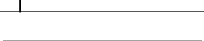
Table of Contents
Table of Contents
Operation Section
1. PRODUCT APPLICATION INFORMATION
1.1 Outline . . . . . . . . . . . . . . . . . . . . . . . . . . . . . . . . . . . . . . . . . . . . . . . . . . . . . . . . . . . . . . . . . . . . . . . . . . . . . . . . 1-1
1.2 Applicable Vehicle . . . . . . . . . . . . . . . . . . . . . . . . . . . . . . . . . . . . . . . . . . . . . . . . . . . . . . . . . . . . . . . . . . . . . . . 1-1
1.3 System Component Part Numbers . . . . . . . . . . . . . . . . . . . . . . . . . . . . . . . . . . . . . . . . . . . . . . . . . . . . . . . . . . 1-1
2. SUPPLY PUMP
2.1 Outline . . . . . . . . . . . . . . . . . . . . . . . . . . . . . . . . . . . . . . . . . . . . . . . . . . . . . . . . . . . . . . . . . . . . . . . . . . . . . . . . 1-3
2.2 Suction Control Valve (SCV) . . . . . . . . . . . . . . . . . . . . . . . . . . . . . . . . . . . . . . . . . . . . . . . . . . . . . . . . . . . . . . . 1-4
2.3 Fuel Temperature Sensor . . . . . . . . . . . . . . . . . . . . . . . . . . . . . . . . . . . . . . . . . . . . . . . . . . . . . . . . . . . . . . . . . 1-7
3. RAIL
3.1 Outline . . . . . . . . . . . . . . . . . . . . . . . . . . . . . . . . . . . . . . . . . . . . . . . . . . . . . . . . . . . . . . . . . . . . . . . . . . . . . . . . 1-8
3.2 Rail Pressure Sensor (Pc Sensor). . . . . . . . . . . . . . . . . . . . . . . . . . . . . . . . . . . . . . . . . . . . . . . . . . . . . . . . . . . 1-9
3.3 Pressure Limiter . . . . . . . . . . . . . . . . . . . . . . . . . . . . . . . . . . . . . . . . . . . . . . . . . . . . . . . . . . . . . . . . . . . . . . . . 1-9
4. INJECTOR (G2 TYPE)
4.1 |
Outline . . . . . . . . . . . . . . . . . . . . . . . . . . . . . . . . . . . . . . . . . . . . . . . . . . . . . . . . . . . . . . . . . . . . . . . . . . . . . . . |
1-10 |
4.2 |
Characteristics. . . . . . . . . . . . . . . . . . . . . . . . . . . . . . . . . . . . . . . . . . . . . . . . . . . . . . . . . . . . . . . . . . . . . . . . . |
1-10 |
4.3 |
Construction . . . . . . . . . . . . . . . . . . . . . . . . . . . . . . . . . . . . . . . . . . . . . . . . . . . . . . . . . . . . . . . . . . . . . . . . . . |
1-11 |
4.4 |
QR Codes . . . . . . . . . . . . . . . . . . . . . . . . . . . . . . . . . . . . . . . . . . . . . . . . . . . . . . . . . . . . . . . . . . . . . . . . . . . . |
1-12 |
5. OPERATION OF CONTROL SYSTEM COMPONENTS
5.1 Engine Control System Diagram . . . . . . . . . . . . . . . . . . . . . . . . . . . . . . . . . . . . . . . . . . . . . . . . . . . . . . . . . . . 1-13 5.2 Engine Electronic Control Unit (ECU) . . . . . . . . . . . . . . . . . . . . . . . . . . . . . . . . . . . . . . . . . . . . . . . . . . . . . . . 1-14 5.3 Camshaft Position Sensor (TDC) . . . . . . . . . . . . . . . . . . . . . . . . . . . . . . . . . . . . . . . . . . . . . . . . . . . . . . . . . . 1-21 5.4 Manifold Absolute Pressure (MAP) Sensor . . . . . . . . . . . . . . . . . . . . . . . . . . . . . . . . . . . . . . . . . . . . . . . . . . . 1-22 5.5 Mass Air Flow (MAF) Meter. . . . . . . . . . . . . . . . . . . . . . . . . . . . . . . . . . . . . . . . . . . . . . . . . . . . . . . . . . . . . . . 1-23 5.6 Diesel Throttle . . . . . . . . . . . . . . . . . . . . . . . . . . . . . . . . . . . . . . . . . . . . . . . . . . . . . . . . . . . . . . . . . . . . . . . . . 1-24
6. FUEL INJECTION CONTROL
6.1 |
Outline . . . . . . . . . . . . . . . . . . . . . . . . . . . . . . . . . . . . . . . . . . . . . . . . . . . . . . . . . . . . . . . . . . . . . . . . . . . . . . . |
1-25 |
6.2 |
Fuel Injection Quantity Control . . . . . . . . . . . . . . . . . . . . . . . . . . . . . . . . . . . . . . . . . . . . . . . . . . . . . . . . . . . . |
1-25 |
6.3 |
Other Controls . . . . . . . . . . . . . . . . . . . . . . . . . . . . . . . . . . . . . . . . . . . . . . . . . . . . . . . . . . . . . . . . . . . . . . . . . |
1-27 |
7. OTHER SYSTEMS
7.1 |
Outline . . . . . . . . . . . . . . . . . . . . . . . . . . . . . . . . . . . . . . . . . . . . . . . . . . . . . . . . . . . . . . . . . . . . . . . . . . . . . . . |
1-29 |
7.2 |
Diesel Particulate Filter (DPF) System . . . . . . . . . . . . . . . . . . . . . . . . . . . . . . . . . . . . . . . . . . . . . . . . . . . . . . |
1-29 |
8. DIAGNOSTIC TROUBLE CODES (DTC)
8.1 Codes Shown in the Table. . . . . . . . . . . . . . . . . . . . . . . . . . . . . . . . . . . . . . . . . . . . . . . . . . . . . . . . . . . . . . . . 1-30
8.2 DTC Details . . . . . . . . . . . . . . . . . . . . . . . . . . . . . . . . . . . . . . . . . . . . . . . . . . . . . . . . . . . . . . . . . . . . . . . . . . . 1-30

Table of Contents

Operation Section
1 1
1.PRODUCT APPLICATION INFORMATION
1.1Outline
This manual describes the 4M41 engine Common Rail System (CRS) installed in the MITSUBISHI PAJERO, on sale from September 2006. As of September 2008, the 4M41 engine CRS has been changed as per the list below. As such, this manual contains additional information related to the aforementioned changes.
Supply pump change
Injector change
Diagnostic Trouble Code (DTC) changes
1.2Applicable Vehicle
Vehicle Manufacturer |
Vehicle Name |
Engine Model |
Specification |
Destination |
Line Off Period |
|
|
|
|
|
|
MITSUBISHI |
PAJERO |
4M41 |
4WD (MT/AT) |
Europe, Australia |
Sep, 2006* |
*: The engine model has not been changed since September 2006. However, the specifications have changed as of September 2008.
1.3System Component Part Numbers
Part Name |
DENSO |
Manufacturer |
Remarks |
||
Part Name |
Part Name |
||||
|
|
|
|||
|
|
|
|
||
Supply pump |
SM294000-034# |
1460A003 |
Sept. 2006 to Aug. 2008 |
||
|
|
|
|
||
SM294000-107# |
1460A040 |
from Sept. 2008 |
|||
|
|||||
|
|
|
Sept. 2006 to Aug. 2008 |
||
Injector |
SM095000-576# |
1465A054 |
|||
|
|
from Sept. 2008 |
|||
SM095000-750# |
1465A279 |
||||
|
|||||
|
|
|
|||
|
|
|
|
|
|
Rail |
SM095440-064# |
1465A034 |
|
|
|
|
|
|
|
||
|
|
|
Sept. 2006 to Aug. 2008 |
||
|
275800-468# |
1860A699 |
Manual |
transmission |
|
|
|
|
vehicles only |
|
|
|
|
|
|
||
|
|
|
Sept. 2006 to Aug. 2008 |
||
|
275800-469# |
1860A702 |
Automatic |
transmission |
|
Engine ECU |
|
|
vehicles only |
|
|
|
|
|
|
||
|
275800-932# |
1860B029 |
from Sept. 2008 |
||
|
|
|
|
||
|
275800-933# |
1860B028 |
from Sept. 2008 |
||
|
|
|
|
||
|
275800-934# |
1860B027 |
from Sept. 2008 |
||
|
|
|
|
||
|
275800-935# |
1860A261 |
from Sept. 2008 |
||
|
|
|
|
||
|
275800-936# |
1860B100 |
from Sept. 2008 |
||
|
|
|
|
|
|

Operation Section
1 2
Part Name |
DENSO |
Manufacturer |
Remarks |
|
Part Name |
Part Name |
|||
|
|
|||
|
|
|
|
|
Manifold absolute pressure (MAP) |
079800-779# |
1865A035 |
|
|
sensor |
|
|
|
|
|
|
|
|
|
Diesel throttle |
197920-002# |
1450A033 |
|
|
|
|
|
|
|
Fuel temperature sensor |
179730-002# |
MR547077 |
|
|
|
|
|
|
|
Mass air flow (MAF) meter |
197400-227# |
1525A016 |
|
|
|
|
|
|
|
Exhaust gas temperature sensor 1 |
265600-145# |
1587A013 |
|
|
|
|
|
|
|
Exhaust gas temperature sensor 2 |
265600-146# |
1587A014 |
|
|
|
|
|
|
|
Exhaust gas temperature sensor 3 |
265600-147# |
1587A015 |
|
|
|
|
|
|
|
Differential pressure sensor |
104990-136# |
1865A087 |
|
|
|
|
|
Automatic transmission |
|
Absolute pressure sensor |
104990-135# |
0865A086 |
||
|
|
|
vehicles only |
|
Temperature sensor for differential |
170400-602# |
1865A095 |
||
|
||||
pressure sensor |
|
|||
|
|
|
||
|
|
|
|
|
Electric-Vacuum Regulating Valve |
|
|
|
|
(E-VRV) for Variable Geometry |
139700-035# |
MR258166 |
|
|
Turbo (VGT) |
|
|
|
|
|
|
|
|

Operation Section
1 3
2. SUPPLY PUMP
2.1 Outline
The supply pump consists primarily of the pump body (eccentric cam, ring cam, and plungers), SCV (Suction Control Valve), fuel temperature sensor, and feed pump.
The two plungers are positioned vertically on the outer ring cam for compactness.
The engine drives the supply pump at a ratio of 1:1. The supply pump has a built-in feed pump (trochoid type). The feed pump draws in fuel from the fuel tank for delivery to the plunger chamber.
The internal camshaft drives the two plungers which pressurize the fuel sent to the plunger chamber, and then send the fuel to the rail. The quantity of fuel supplied to the rail is controlled by the SCV via signals from the engine ECU. The SCV is a normally open type (the intake valve is open during de-energization). The HP3 supply pump was equipped with a compact SCV. However, the SCV was changed to the conventional type as of September 2008.
For information on basic HP3 supply pump operation (suction from the fuel tank, fuel delivery to the rail, etc.), refer to the publication entitled, "General Edition Manual: Common Rail System (Doc ID: 00400076E)."
|
|
|
|
|
|
|
|
|
|
|
|
|
|
|
|
|
|
|
|
|
|
|
|
||
|
|
|
|
|
|
|
|
|
|||
|
|
|
|
|
|
|
|
|
|
||
|
|
|
|
|
|
|
|
|
|
|
|
|
|
|
|
|
|
|
|
|
|
|
|
|
|
|
|
|
|
|
|
|
|
Exterior View

Operation Section
1 4
2.2 Suction Control Valve (SCV)
The supply pump for the 4M41 engine CRS is equipped with a normally open type SCV. From September 2006 to August 2008, a compact SCV was used. However, the SCV was changed to the conventional type as of September 2008.
While both the conventional and compact type SCVs have identical functions, the operation method differs. When the solenoid is not energized, the return spring pushes against the needle valve, completely opening the fuel passage and supplying fuel to the plungers. (Total quantity suctioned  Total quantity discharged) When the solenoid is energized, the armature pushes the needle valve, which compresses the return spring and closes the passage. In contrast, the needle valve in the compact SCV is pulled upon, which compresses the return spring and closes the fuel passage.
The solenoid is actuated by the duty ratio control. Fuel is supplied in an amount corresponding to the open surface area of the passage, which depends on the duty ratio. Fuel is then discharged by the plungers.
|
|
|
|
|
|
||
|
|
||
|
|
|
Conventional SCV: from September 2008
Compact SCV: from September 2006 to August 2008

Operation Section
1 5
(1)When the SCV energized duration (duty ON time) is short
When the SCV energization time is short, the average current flowing through the solenoid is small. As a result, the needle valve is returned by spring force, creating a large valve opening. Subsequently, the fuel suction quantity increases.
|
|
|
|
|
|
|
|
|
|
Conventional SCV: from September 2008
|
|
|
|
|
|
|
||
|
||
|
|
Compact SCV: from September 2006 to August 2008

Operation Section
1 6
(2)When the SCV energized duration (duty ON time) is long
When the energization time is long, the average current flowing to the solenoid is large. As a result, the needle valve is pressed out (in the compact SCV, the needle valve is pulled), creating a small valve opening. Subsequently, the fuel suction quantity decreases.
|
|
|
|
|
|
|
|
|
|
Conventional SCV: from September 2008
|
|
|
|
|
|
|
|
|
|
||
|
||
|
|
Compact SCV: from September 2006 to August 2008
Operation Section
1 7
2.3 Fuel Temperature Sensor
Detects the fuel temperature and sends a corresponding signal to the engine ECU. Based on this information, the engine ECU calculates the injection volume correction that is appropriate for the fuel temperature.
|
|
|
|
|
|
|
|
|
|
|
|
|
|
|
|
|
|
|
|
|
|
|
|
|
|
|
|
|
|
|
|
|
|
|
|
|
|
|
|
Operation Section
1 8
3.RAIL
3.1Outline
The rail stores pressurized fuel (25 to 180 MPa) that has been delivered from the supply pump and distributes the fuel to each cylinder injector. The rail is equipped with a rail pressure sensor and a pressure limiter valve.
The rail pressure sensor (Pc sensor) detects fuel pressure in the rail and sends a signal to the engine ECU; the pressure limiter controls the excess pressure. As a result, both optimum combustion and a combustion noise reduction are achieved.
|
|
|
|
|
|
|
|
|||||
|
|
|
|
|
|
|
|
|
|
|
|
|
|
|
|
|
|
|
|
|
|
|
|
|
|
|
|
|
|
|
|
|
|
|
|
|
|
|
|
|
|
|
|
|
|
|
|
|
|
|
|
|
|
|
|
|
|
|
|
|
|
|
|
|
|
|
|
|
|
|
|
|
|
|
|
|
|
|
|
|
|
|
|
|
|
|
|
|
|
|
|
|
|
|
|
|
|
|
|
|
|
|
|
Operation Section
1 9
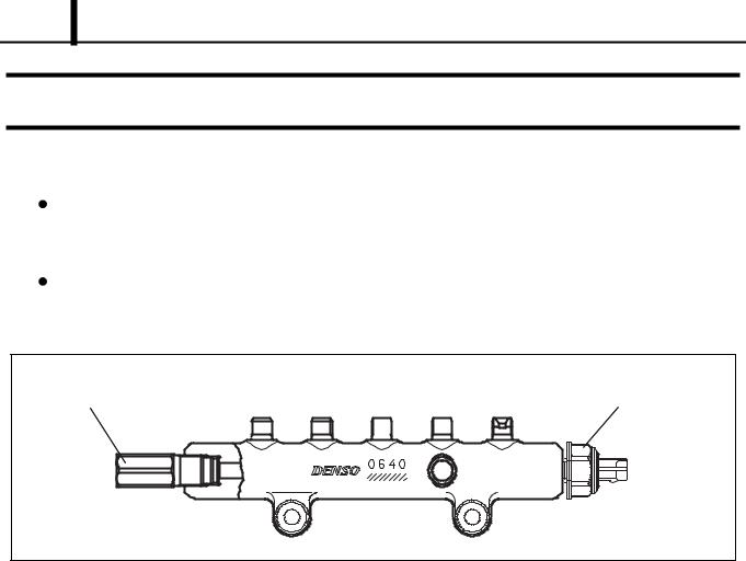
3.2 Rail Pressure Sensor (Pc Sensor)
The pressure sensor detects the fuel pressure of the rail, and sends a signal to the engine ECU. The sensor is made from a semiconductor that uses the Piezo resistive effect to detect changes in electrical resistance based on the pressure applied to the elemental silicon. In comparison to the old model, this sensor is compatible with high pressure.
|
|
|
|
|
|
|
|
|
|
|
|
|
|
|
|
|
|
|
|
|
|
|
|
|
|
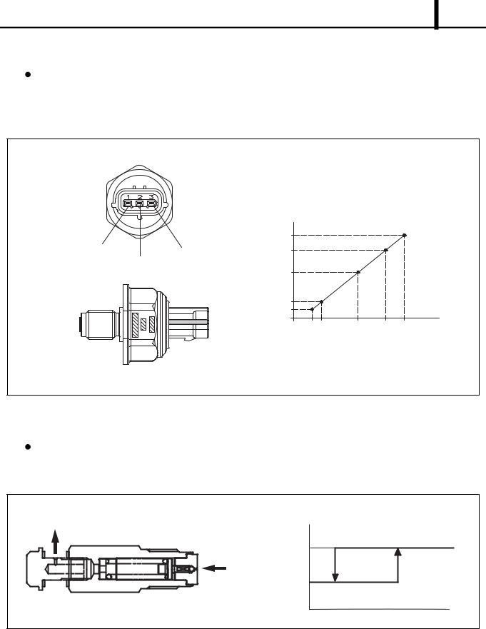
3.3 Pressure Limiter
The pressure limiter releases pressure when the internal rail pressure becomes abnormally high. The pressure limiter opens when internal pressure reaches 221 MPa (2254 kg/cm2), and closes when rail pressure reaches a given set pressure. Fuel released from the pressure limiter is returned to the fuel tank.
 Loading...