


Mitsubishi Electric Air Conditioner Network System
DIDO controller
PAC-YG66DCA
Installation/Instruction Manual
Contents
|
|
|
Page |
1. |
Safety Precautions.............................................. |
1 |
|
2. |
Device Capabilities ............................................. |
1 |
|
3. |
Confirmation of Parts .......................................... |
2 |
|
4. |
Specifications...................................................... |
2 |
|
|
4-1. |
Product Specifications ....................... |
2 |
|
4-2. |
External View ..................................... |
3 |
5. |
Example of System Configuration....................... |
3 |
|
6. |
Installation Method.............................................. |
4 |
|
|
6-1. |
Parts to be Procured Locally.............. |
4 |
|
6-2. |
Installation Procedure ........................ |
4 |
7. |
Wiring Method..................................................... |
6 |
|
|
7-1. |
Names of Parts .................................. |
6 |
|
7-2. |
Connecting the Power Line and |
|
|
|
M-NET Transmission Line ................. |
7 |
|
7-3. |
Connecting the Signal Lines .............. |
7 |
|
7-3-1. |
Standard Terminals |
|
|
|
(Channels 1 and 2) ............................ |
8 |
|
(1) |
Inputs ................................................. |
8 |
|
|
(a) Non-voltage a Contact Inputs....... |
8 |
|
(2) |
Outputs .............................................. |
8 |
|
|
(a) Non-voltage Relay Contact |
|
|
|
Outputs......................................... |
8 |
|
|
(b) Transistor Outputs |
|
|
|
(Open Collector) ........................... |
9 |
|
7-3-2. |
Expansion Connectors |
|
|
|
(Channels 3 to 6) ............................. |
10 |
|
(1) |
Expansion Inputs/Outputs................ |
10 |
8. |
Initial Setting Procedure.................................... |
11 |
|
9. |
Switch List......................................................... |
12 |
|
10. |
Display Content................................................. |
13 |
|
|
10-1. |
Display Content List ......................... |
13 |
|
10-2. |
Communication Error Status |
|
|
|
Display ............................................. |
14 |
11. |
Test Run |
........................................................... |
14 |
Before using the DIDO controller, please read this installation/instruction manual carefully to ensure proper operation. Keep this installation/instruction manual for future reference.

1 Safety Precautions
•Before using the device, thoroughly read the following safety precautions and use as directed.
•Hazards and levels of danger that can occur due to incorrect handling are classified by the following symbols.
Warning |
Incorrect handling can result in death, serious injury, etc. |
|
|
Caution |
Incorrect handling can result in injury or damage to the building or its contents. |
|
|
•After reading this manual, keep this manual for future reference. When the device is reinstalled or repaired, give this manual to those who provide these services. When the user changes, make sure that the new user receives this manual.
 WARNING
Ask your dealer or a qualified technician to install the device.
Improper installation by the user may result in electric shock or fire.
Properly install the device on a surface that can withstand the weight of the device.
Device installed on an unstable surface may fall and cause injury.
Only use specified cables. Securely connect each cable so that the terminals do not carry the weight of the cable.
Improperly connected or fixed cables or short-circuited cables may produce heat and/or result in fire.
Do not make any modifications or alternations to the device.
Modifications or improper repair may result in electric shock or fire. Consult your dealer for repair.
Properly install the device according to the instructions in this manual.
Improper installation may result in electric shock or fire.
Have all electrical work performed by an authorized electrician according to the local regulations and instructions in this manual.
Power supply circuit capacity shortage or improper installation may result in electric shock or fire. Ask your dealer or a specialist when performing an electrical work.
Do not move or reinstall the device by yourself.
Improper installation may result in electric shock or fire. Consult your dealer or a specialist when moving or reinstalling the device.
 CAUTION
Do not install the device where a flammable gas leak may occur.
If a flammable gas leaks and piles up around the device, it may be ignited and/or explode.
Do not use the device in an unusual environment.
If the device is installed where a large amount of oil (including machine oil), steam or sulfidizing gas is present, this environment may lead the device to a remarkable drop in performance or damage its parts.
Do not install the device where a large amount of steam rises, such as in the bathroom or kitchen.
Avoid installing this device where dew condensation occurs. If the device is installed in such places, it may result in electric shock or malfunctions.
Do not install the device where acidic or alkaline solutions or chemical sprays are used frequently.
Doing so may lead to electric shock or malfunctions.
When installing the device in a hospital, communication station, or similar place, provide sufficient protection against noise.
An inverter equipment, private power generator, high-frequency medical equipment or radio communication equipment may interfere with the normal operation of this device. On the other hand, the device may affect such equipment by creating noise that disturbs medical treatment or image broadcasting.
Do not put tension on the power supply wires.
If tension is put on the wires, they may break and result in excessive heat and/or fire.
Do not immerse the device in water.
Doing so may lead to electric shock or malfunctions.
Do not install the device where the temperature may become more than 40°C [104°F] or less than 0°C [32°F] or it will be subjected to direct sunlight.
If the device is installed in such place, it may result in deformation or malfunctions.
Use standard products with the proper current capacity.
The use of non-standard wires may result in current leak, excessive heat, and/or fire.
Do not touch the main board with hands or tools. Prevent dust from forming on the board.
Doing so may result in fire or malfunctions.
Do not apply an AC power source. The maximum applied voltage for the device is 24 VDC.
Using the incorrect voltage may result in device failure, ignition, and/or fire.
2 Device Capabilities
This device can be used in combination with a system controller to operate/stop general-purpose equipment, as well as to monitor the operating status and error status.
Furthermore, this device is equipped with two sets (channels 1 and 2) of standard terminals and four sets of expansion connectors as the input/output terminals.
In addition to the above, this device also features an interlock function that interlocks M-NET devices for indoor units, etc. set in advance and performs settings such as temperature control and operation/stoppage using the status of contact terminals.
 Caution: Usage Restrictions
•We take no responsibility for compensation for damages caused by reasons not attributable to us, for opportunities lost as a result of a failure of this device or an electrical power failure on the customer or any third party site, for damages caused by special circumstances, regardless of whether we can predict them or not, for secondary damages, for accidental damages, or for damages to objects other than this device.
We also take no responsibility for compensation for damages caused by the customer's work, including, but not limited to, replacement work, readjustment of machinery and equipment on the local site, and startup and trial operation.
•Do not use this device for disaster prevention control and security control. (In particular, do not use this device in life critical applications.)
•It is recommended to provide a circuit such as an external switch capable of turning operation on/off from general-purpose equipment in case operation of the general-purpose equipment becomes no longer possible because of a failure of the DIDO controller or a peripheral part.
1

3 |
Confirmation of Parts |
|
|
||
|
• |
Confirm that the box contains the following parts. |
|
||
|
|
|
|
|
|
|
|
Number |
|
Part Name |
Quantity |
|
|
|
|
|
|
|
|
1 |
|
DIDO controller |
1 |
|
|
2 |
|
Installation/instruction manual (this document) |
1 |
*In addition to the parts mentioned above, other parts need to be procured locally in order to operate this device. Furthermore, other Mitsubishi optional parts may be required depending on how the device is to be used.
For details, refer to "6 Installation Method".
4 Specifications
4-1. Product Specifications
Item |
|
|
|
|
|
Rating and Specification |
|
|||
|
|
|
|
|
|
|
|
|
|
|
Power Supply |
24 VDC±10%: 5 W (*1) |
|
|
|
|
Screw terminal block (M3) |
||||
|
M-NET communication |
|
17 to 30 VDC (*2) |
|
|
Screw terminal block (M3) |
||||
|
|
|
|
|
|
|
Applied load |
|
|
|
|
|
|
|
|
|
Non-voltage Relay contact |
MAX: 24 VDC, 5 W |
|
Screw terminal block |
|
|
|
|
|
ON/OFF, |
MIN: 5 VDC, 2 mW |
|
||||
|
|
|
|
(2) |
|
(M3.5) |
||||
|
|
|
|
(ON) |
|
|
* AC loads cannot be |
|
|
|
|
|
|
|
(*4) |
|
|
connected. |
|
|
|
|
|
|
|
|
|
Transistor (2) |
24 VDC 40 mA or less |
|
Screwless terminal block |
|
|
Standard |
Output |
|
|
|
(*5) |
|
|||
|
|
|
|
|
|
|
||||
|
(*3) |
|
|
|
|
|
|
|
||
|
|
|
|
(2) |
MIN: 5 VDC, 2 mW |
|
(M3.5) |
|||
|
|
|
|
|
|
Applied load |
|
|
||
|
|
|
|
|
|
Non-voltage Relay contact |
MAX: 24 VDC, 5 W |
|
Screw terminal block |
|
|
|
|
|
(OFF) |
|
|
|
|||
Interface |
|
|
|
|
|
* AC loads cannot be |
|
|
||
|
|
|
(*4) |
|
|
connected. |
|
|
||
|
|
|
|
|
|
|
|
|||
|
|
|
|
|
|
Transistor (2) |
24 VDC 40 mA or less |
|
Screwless terminal block |
|
|
|
|
|
|
|
(*5) |
|
|||
|
|
|
|
|
|
|
|
|
||
|
|
Input |
|
ON/OFF |
Non-voltage a contact |
24 VDC 1 mA or less |
|
Screwless terminal block |
||
|
|
|
Error/Normal |
(2 each) |
(*6) |
|
||||
|
|
|
|
|
|
|||||
|
Expansion |
Output |
|
ON/OFF, (ON) |
|
24 VDC 40 mA or less |
|
|
||
|
|
|
(*4) |
Transistor (4 each) |
|
9 pin connector |
||||
|
Input |
|
|
|
24 VDC input (4 each) |
24 VDC 1 mA or less |
|
9 pin connector |
||
|
|
(*3) |
|
(OFF) |
(*4) |
|
(*5) |
|
|
|
|
|
|
|
|
|
|
|
|||
|
|
|
|
ON/OFF |
|
(*7) |
|
|
||
|
|
|
|
Error/Normal |
|
|
|
|||
Interlock |
Interlock M-NET devices and output contacts according to status of input contacts. (*8) |
|
||||||||
Function |
|
|||||||||
|
|
|
|
|
|
|
|
|
||
Environment |
Temperature |
|
|
Operating temperature range |
0 to 40°C [32°F to 104°F] |
|
||||
|
|
Storage temperature range |
-20 to 60°C [-4°F to 140°F] |
|||||||
Conditions |
|
|
|
|
|
|||||
Humidity |
|
|
30 to 90%RH (no condensation) |
|
||||||
|
|
|
|
|||||||
Dimensions |
200 (W) × 120 (H) × 45 (D) mm / 77/8 (W) × 43/4 (H) × 125/32 (D) in |
|
||||||||
Weight |
0.6 kg / 1 3/8 lb |
|
|
|
|
|
|
|||
Current Time |
If the power is cut, the internal capacitor will keep counting the current time normally for approximately one week. |
|||||||||
Backup during |
||||||||||
(The internal capacitor takes approximately a day to charge. Replacement of a battery is not necessary.) |
||||||||||
Power Failure |
||||||||||
|
|
|
|
|
|
|
|
|
||
Installation |
Inside a control panel (indoors) |
|
|
|
|
|||||
Environment |
* Use this product in a hotel, a business office environment or similar environment. |
|
||||||||
*1: For details, refer to "6-1 Parts to be Procured Locally".
*2: Supply electric power from a power unit for the transmission line or an outdoor unit. Furthermore, the power consumption factor of the M-NET circuitry of this device is "1/4" (equivalent to one ME Remote Controller).
*3: Non-voltage Relay contact or transistor is available for output. Only one can be used at a time. *4: ( ) is in the case of a pulse.
*5: The output is open collector type. Power must be supplied from an external power source to the output circuit of this device. *6: Power is supplied from this device to the external contacts.
*7: Power must be supplied from an external power source.
*8: Interlock control is performed from the Maintenance Tool. For details, refer to the instruction manual for the Maintenance Tool.
2

4-2. External View
107.6 (41/4)
15 (19/32)
) |
/32 |
11 |
( |
26 |
111 (43/8) |
|
200 (77/8) |
|
|
|
|
|
|
||
|
150 (529/32) |
|
|
|
|
|
|
||
52 (21/16) |
|
46.5 (127/32) |
|
|
4.5 |
|
|
||
|
|
|
|
|
|
|
(3/16) |
|
|
|
DIDO controller |
|
|
|
|
|
|
|
|
|
PAC-YG66DCA |
|
|
|
|
|
|
|
|
|
[ OUTPUT ] Transistor Output 24 VDC |
[ OUTPUT ] Non-voltage Contact Output |
|
|
|||||
|
[ Junction Terminal ] |
Ch1 |
|
Ch2 |
Ch1 |
Ch2 |
|
|
|
|
ON/OFF,(ON) |
(OFF) |
ON/OFF,(ON) (OFF) |
ON/OFF,(ON) |
(OFF) ON/OFF,(ON) |
(OFF) |
|
|
|
|
[ Output LEDs ] |
|
|
|
|
|
|
|
|
|
Ch1 |
Ch2 |
|
|
|
|
|
||
|
ON/OFF |
(OFF) |
ON/OFF |
(OFF) |
|
|
|
|
|
|
(ON) |
(ON) |
|
|
|
|
|
||
|
|
|
|
|
|
|
|
) |
44/3 |
|
|
|
|
|
|
|
|
32/ |
|
|
|
|
|
|
|
N623 |
|
|
) |
|
|
|
|
|
|
|
|
|
|
|
|
|
|
DIDO controller |
|
411 ( |
|||
|
|
|
|
|
( |
120 |
|||
|
|
|
|
MODEL PAC-YG66DCA |
110 |
||||
|
|
|
|
SERVICE REF. PAC-YG66MCA-J |
|
|
|
||
|
|
|
|
INPUT VOLTAGE |
DC24V;0.2A |
|
|
||
This device complies with Part15 of the FCC Rules.Operation is |
WEIGHT |
0.6 kg / 13/8 lb |
|
|
|||||
subject to the following two conditions: (1)this device may not cause |
SERIAL No. |
|
|
|
|
||||
harmful interference, and (2)this device must accept any interference |
|
|
|
|
|
|
|||
received, including interference that may cause undesired operation. |
MADE IN |
JAPAN |
|
|
|
|
|||
[ Expansion I/O ] |
[ INPUT ] |
|
|
|
|
[ 24 VDC Power Supply] |
|
|
|
Ch5,Ch6 Ch3,Ch4 |
Ch1 |
|
Ch2 |
|
|
|
|
|
|
ON/OFF |
Error |
ON/OFF Error |
|
|
|
|
|
||
26 (11/32) |
83.5 (35/16) |
27 (13/32) |
45(125/32) 9 (3/8)
Unit: mm (in)
) |
/32 |
11 |
( |
26 |
5 Example of System Configuration
Centralized control line
Power supply unit PAC-SC50KUA
M-NET M-NET
LAN G-50A or GB-50A or
(a)ON/OFF, (ON) output
(b)(OFF) output
(c)ON/OFF input
(d)Error/Normal input
Standard: Terminal block (for 2 units) Expansion: Connectors (for 4 units)
Total: 6 units
<Restrictions>
Maximum of 50 units (50 channels) per G(B)-50A
However, the number of units that can be connected to a G(B)-50A is up to 50 including the number of contacts used on this device, an indoor unit, Lossnay unit, etc.
Indoor control line
|
|
|
|
|
|
24 VDC |
|
|
DIDO controller |
|
|||
City Multi |
|
|
Power supply |
|||
|
|
|
|
|
||
|
(a) (b) |
|
|
|
|
|
|
|
|
|
|
||
(c) |
(d) |
|
|
|||
|
|
|
|
|
||
|
|
|
|
|
|
|
System remote controller, ON/OFF remote controller, Schedule timer
G(B)-50A Web or
TG-2000A
Note:
|
|
|
|
|
|
|
|
|
|
|
|
|
|
Ventilation fan, |
× up to 6 units |
|
|
|
|
|
|
|
|
|
|
|
|
|
|
|
lighting, etc. |
||
|
|
|
|
|
|
|
|
|
|
|
|
|
|
|
||
|
|
|
|
|
|
|
|
|
|
|
|
|||||
|
|
|
DIDO controller |
|
|
|
|
|
|
|
||||||
|
|
|
|
|
|
|
|
|
|
|
|
|
|
|
|
|
|
|
|
|
|
|
|
|
|
|
|
|
|
24 VDC |
|
|
|
|
|
|
|
|
|
|
|
|
|
|
|
|||||
|
|
|
(a) |
(b) |
|
(c) |
|
(d) |
|
|
|
Power supply |
|
|
||
|
|
|
|
|
|
|||||||||||
|
|
|
|
|
|
|
|
|
|
|
||||||
|
|
|
Ventilation fan, |
|
× up to 6 units |
|
||||||||||
|
|
|
lighting, etc. |
|
|
|||||||||||
|
|
|
|
|
|
|
|
|
|
|
||||||
|
|
|
|
|
|
|
|
|
|
|
|
|
|
|
|
|
* This figure omits the power supply line and only shows the transmission line.
•For the shield ground of the M-NET centralized control line, use single-point grounding at the power unit for the transmission line.
However, when supplying electric power to the M-NET centralized control line from the R410A series outdoor unit without using a power supply unit for the transmission line, use single-point grounding at the TB7 of that outdoor unit.
Furthermore, when connecting this device to the M-NET indoor control line, use grounding at the TB3 for each outdoor unit system.
•If this device is connected to the M-NET indoor control line and the outdoor unit is down because, for example, the power supply is interrupted for servicing or there is a failure, the DIDO controller cannot be controlled from the system controller.
•Controlling the system remote controller, ON/OFF remote controller, and schedule timer is only possible with channel 1 of a standard terminal.
•When G(B)-50A is connected, monitoring control can only be performed from G(B)-50A Web or TG-2000A. Monitoring control cannot be performed from the system remote controller, ON/OFF remote controller or schedule timer.
3
6 Installation Method
6-1. Parts to be Procured Locally
Prepare the following parts to install this device.
Required Part |
|
Specification |
|
|
|
|
|
|
|
Unit fixing screws |
M4 screw × 4 |
|
|
|
|
Power source: 24 VDC±10% 0.2 A (Minimum loading), SELV circuit, power line with grounding terminal |
|||
|
Ripple noise: Lower than 200 mVp-p |
|
||
|
Compatible specification |
|
||
|
Authorized or CE marked products |
|
||
Power supply for this |
Subject to regulations: - IEC60950 (or EN60950) |
|
||
|
- CISPR22/24 (or EN55022/24) |
|
||
unit |
|
- IEC61000-3-2/3-3 (or EN61000-3-2/3-3) |
||
|
When using transistor output (including extension output) for the 24 VDC output of this device, increase the |
|||
|
capacity to match the number used. |
|
||
|
• 1 set used: 0.3 ADC (Minimum) • 2 sets used: 0.4 ADC (Minimum) • 3 sets used: 0.5 ADC (Minimum) |
|||
|
• 4 sets used: 0.6 ADC (Minimum) • 5 sets used: 0.7 ADC (Minimum) • 6 sets used: 0.8 ADC (Minimum) |
|||
|
* The increase of the power supply capacity is 0.1 ADC for every set. |
|||
Power line |
Use a sheathed vinyl cord or cable. At least 0.75 mm² (AWG18) |
|
||
|
Type of the cable: Sheathed vinyl cords or cable which comply with the following specifications or equivalent. |
|||
|
• CPEV Φ1.2 mm to Φ1.6 mm • CVVS 1.25 mm² to 2 mm² (AWG 16 to 14) |
|||
M-NET transmission |
* CPEV: PE insulated PVC jacketed shielded communication cable |
|
||
line |
* CVVS: PVC insulated PVC jacketed shielded control cable |
|
||
PE: Polyethylene PVC: Polyvinyl choloride |
|
|||
|
Power needs to be supplied to the M-NET circuitry of this device. Use an outdoor unit or a separately purchased |
|||
|
power supply unit for the transmission line. |
|
||
|
Use electric wire of an appropriate size for the terminal block of this device. |
|||
Signal lines |
Electric wire size ···· (1) Solid wire: Φ0.65 mm (AWG21) – Φ1.2 mm (AWG16) |
|||
|
(2) Stranded wire: 0.75 mm² (AWG18) – 1.25 mm² (AWG16) |
|||
|
|
Single strand: At least Φ0.18 mm |
||
|
To use an expansion input/output, use a separately purchased external input/output adapter. |
|||
[Parts to be Purchased Separately] |
|
|
||
|
|
|
|
|
Name |
Model |
Application |
Remark |
|
|
|
|
|
|
Power supply unit |
PAC-SC50KUA |
Power supply to the M-NET transmission line |
This is not required when power is to be |
|
|
|
|
supplied from an outdoor unit. |
|
External I/O adapter |
PAC-YG10HA |
Connection adapter for using an expansion |
This is required when an expansion input/ |
|
input/output |
output is used. |
|||
|
|
|||
6-2. Installation Procedure
The DIDO controller PAC-YG66DCA does not have a waterproof structure.
Be sure to install the DIDO controller inside a control panel that is located indoors.
Prepare a control panel capable of storing this device such as the one shown in the figure. (Install the device in a control panel strong enough to withstand a weight of 0.6 kg [13/8 lb].)
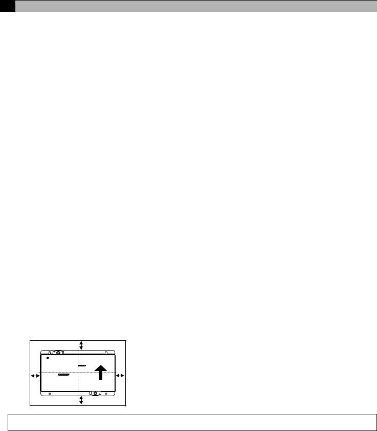
This device can be installed flat or vertically. Clear the space shown below when installing.
|
100 |
|
(315/16) |
100 |
100 |
(315/16) |
(315/16) |
|
100 |
|
(315/16) |
Size of the device: 200 (W) × 120 (H) × 45 (D) mm/ 77/8 (W) × 43/4 (H) × 125/32 (D) in
Unit: mm (in)
Note: The space shown above does not include space for peripherals. Additionally, the amount of space necessary varies according to the functions that are used and the wiring method. Secure enough space appropriate for the type of installation.
4
 Loading...