


Interface (Cased)
PAC-IF013B-E |
PAC-SIF013B-E |
|
|
|
|
|
|
|
|
INSTALLATION MANUAL |
|
|
|
|
|
FOR INSTALLER |
|
English (EN) |
|
For safe and correct use, read this manual thoroughly before installing the interface unit. |
|
|
||
OPERATION MANUAL |
|
|
|
|
|
FOR USER |
|
|
|
For safe and correct use, please read this operation manual thoroughly before operating the interface |
unit. |
|
|
|
INSTALLATIONSHANDBUCH |
|
|
|
|
|
FÜR INSTALLATEURE |
|
Deutsch (DE) |
|
Aus Sicherheitsgründen und zur richtigen Verwendung vor der Installation der Schnittstelleneinheit das vorliegende |
Handbuch gründlich durchlesen. |
|
||
BEDIENUNGSHANDBUCH |
|
|
|
|
|
FÜR BENUTZER |
|
|
|
Aus Sicherheitsgründen und zur richtigen Verwendung vor dem Betrieb der Schnittstelleneinheit das vorliegende Bedienungshandbuch gründlich durchlesen. |
|
|
||
MANUEL D’INSTALLATION |
|
|
|
|
|
POUR L’INSTALLATEUR |
|
Français (FR) |
|
Avant d’installer l’unité d’interface, lire attentivement ce manuel pour une utilisation sûre et correcte. |
|
|
||
MANUEL D’UTILISATION |
|
|
|
|
|
POUR L’UTILISATEUR |
|
|
|
Avant d’installer l’unité d’interface, lire attentivement ce guide d’utilisation pour une utilisation sûre et |
correcte. |
|
|
|
INSTALLATIEHANDLEIDING |
|
|
|
|
|
VOOR DE INSTALLATEUR |
|
Nederlands (NL) |
|
Lees deze handleiding voor een veilig en juist gebruik goed door voordat u met het installeren van het interface-apparaat begint. |
||||
BEDIENINGSHANDLEIDING |
|
|
|
|
|
VOOR DE GEBRUIKER |
|
|
|
Lees deze bedieningshandleiding voor een veilig en juist gebruik goed door voordat u het interface-apparaat bedient.
MANUAL DE INSTALACIÓN |
|
|
|
PARA EL INSTALADOR |
|
Español (ES) |
|
Para un uso correcto y seguro, lea detalladamente este manual antes de instalar la unidad de interfaz. |
|
|
|
MANUAL DE INSTRUCCIONES |
|
|
|
PARA EL USUARIO |
|
|
|
Para un uso correcto y seguro, lea detalladamente este manual de instrucciones antes de instalar la |
unidad de interfaz. |
|
|
MANUALE DI INSTALLAZIONE |
|
|
|
PER L’INSTALLATORE |
|
Italiano (IT) |
|
Per un uso sicuro e corretto, leggere attentamente il presente manuale prima di installare l’unità interfaccia. |
|||
ISTRUZIONI DI FUNZIONAMENTO |
|
|
|
PER L’UTENTE |
|
|
|
Per un uso sicuro e corretto, leggere attentamente le istruzioni di funzionamento prima di utilizzare |
l’unità interfaccia. |
|
|
|
|
|
|
Για την ασφαλή και σωστή χρήση, διαβάστε προσεκτικά αυτό το εγχειρίδιο προτού εγκαταστήσετε τη |
|
|
Eλληνικά (GR) |
μονάδα διασύνδεσης. |
|
||
ΕΓΧΕΙΡΙΔΙΟ ΟΔΗΓΙΩΝ ΧΡΗΣΕΩΣ |
|
|
|
ΓΙΑ ΤΟΝ ΧΡΗΣΤΗ |
|
|
|
Για την ασφαλή και σωστή χρήση, διαβάστε προσεκτικά αυτό το εγχειρίδιο λειτουργίας πριν από τον χειρισμό της μονάδας διασύνδεσης. |
|
|
|
MANUAL DE INSTALAÇÃO |
|
|
|
PARA O INSTALADOR |
|
Português (PT) |
|
Para uma utilização segura e correcta, leia atentamente este manual antes de instalar a unidade de |
interface. |
|
|
MANUAL DE OPERAÇÃO |
|
|
|
PARA O UTILIZADOR |
|
|
|
Para uma utilização segura e correcta, leia atentamente este manual de operação antes de instalar |
a unidade de interface. |
|
|
INSTALLATIONSMANUAL |
|
TIL INSTALLATØREN |
For sikker og korrekt brug skal denne manual læses grundigt igennem, inden interfaceenheden installeres.
Brugsvejledning |
|
TIL BRUGER |
|
For sikker og korrekt brug skal denne brugsanvisning læses grundigt igennem, inden interfaceenheden |
betjenes. |
INSTALLATIONSMANUAL |
|
FÖR INSTALLATÖREN |
Läs igenom denna manual noggrant innan du installerar gränssnittsenheten för en säker och korrekt användning.
Användarmanual |
|
FÖR ANVÄNDAREN |
|
För en säker och korrekt användning, vänligen läs igenom denna driftmanual noggrant innan du använder gränssnittsenheten. |
|
Güvenli ve doğru kullanım için arayüz ünitesini monte etmeye başlamadan önce bu kılavuzu dikkatlice okuyun. |
|
|
|
|
|
Işletme Elkitabı |
|
KULLANICI İÇİN |
|
Güvenli ve doğru kullanım için arayüz ünitesini kullanmaya başlamadan önce lütfen bu kılavuzu dikkatlice okuyun.
Чтобы обеспечить безопасную и правильную эксплуатацию устройства, перед установкой интерфейсного блока внимательно прочтите данное руководство.
РУКОВОДСТВО ПО ЭКСПЛУАТАЦИИ |
|
|
ДЛЯ ПОЛЬЗОВАТЕЛЯ |
|
|
Чтобыобеспечитьбезопаснуюиправильнуюэксплуатациюустройства,передэксплуатациейинтерфейсногоблокавнимательнопрочтите |
данноеруководствопоэксплуатации |
. |
Dansk (DA)
Svenska (SV)
Türkçe (TR)
 (RU)
(RU)

Contents
1. |
Safety precautions..................................................................................... |
2 |
5. |
Remote controller operation..................................................................... |
15 |
2. |
Installing the interface unit......................................................................... |
3 |
6. |
Service and Maintenance........................................................................ |
20 |
3. |
System....................................................................................................... |
4 |
7. |
Requirement on local design................................................................... |
21 |
4. |
Electrical work............................................................................................ |
7 |
|
|
|
|
|
|
|
|
|
EN
1. Safety precautions
Before installing the interface unit, make sure you read all the “Safety precautions”.
Please report to your supply authority or obtain their consent before connecting this equipment to the power supply system.
 Warning:
Precautions that must be observed to prevent injuries or death.
 Caution:
Precautions that must be observed to prevent damages to the unit.
After installation, perform the test run to ensure normal operation. Then explain your customer the “Safety Precautions,” use, and maintenance of the unit based on the information in the Operation Manual provided by local application manufacturer. Both the Installation Manual and the Operation Manual must be given to the user. These manuals must always be kept by the actual users.
 :Indicates a part which must be grounded.
 Warning:
Carefully read the labels attached to the unit.
 Warning:
•The unit must not be installed by the user. Ask an installer or an authorised technician to install the unit. If the unit is installed improperly, electric shock, or fire may be caused.
•For installation work, follow the instructions in the Installation Manual and use tools and pipe components specifically made for use with refrigerant specified in the outdoor unit installation manual.
•The unit must be installed according to the instructions in order to minimize the risk of damages by earthquakes, typhoons, or strong winds. Improperly installed unit may fall down and cause damage or injury.
•The unit must be securely installed on a structure that can sustain its weight. If the unit is mounted on an unstable structure, it may fall down and cause damage or injury.
•All electric work must be performed by a qualified technician according to local regulations and the instructions given in this manual. The unit must be powered by dedicated power lines and the correct voltage and circuit breakers must be used. Power lines with insufficient capacity or incorrect electrical work may result in electric shock or fire.
•Only the specified cables can be used for wiring. Connections must be made securely without tension on the terminals. If cables are connected or installed improperly, It may result in overheating or fire.
•Terminal block cover panel of the unit must be firmly fixed. If the cover panel is mounted improperly, dust and moisture may enter the unit, and it may cause electric shock or fire.
•Make sure to use accessories authorised by Mitsubishi Electric and ask an installer or an authorised technician to install them. If accessories are improperly installed, it may cause electric shock, or fire.
•Do not remodel the unit. Consult an installer for repairs. If alterations or repairs are not performed correctly, it may cause electric shock or fire.
•The user should never attempt to repair the unit or transfer it to another location. If the unit is installed improperly, it may cause electric shock or fire. If the interface unit needs to be repaired or moved, ask an installer or an authorised technician.
•When installing sensors and parts, do not expose the terminals.
1.1. Before installation (Environment)
 Caution:
•Do not install the interface unit in outdoor location as it is designed for indoor installation only. Otherwise electric shock or breakdown may be caused by water drop, wind or dust.
•Do not use the unit in an unusual environment. If the interface unit is installed or exposed to steam, volatile oil (including machine oil), or sulfuric gas, or exposed to briny air, the internal parts can be damaged.
•Do not install the unit where combustible gases may leak, be produced, flow, or accumulate. If combustible gas accumulates around the unit, it may cause fire or explosion.
•When installing the unit in a hospital or in a building where communications equipment are installed, you may need to take measure to noise and electronic interference. Inverters, home appliances, high-frequency medical equipment, and radio communications equipment can cause the interface unit to malfunction or to breakdown. At the same time, the noise and electric interference from the interface unit may disturb the proper operation of medical equipment, and communications equipment.
1.2. Before installation or relocation
Caution: |
|
• Be very careful when moving the units. Do not hold the packaging bands. |
• Be sure to safely dispose of the packaging materials. Packaging materials, |
Wear protective gloves to unpack and to move it, in order to avoid your |
such as nails and other metal or wooden parts may cause injury. |
hands being injured by parts. |
• Do not wash the interface unit. You may receive an electric shock. |
1.3. Before electric work
 Caution:
•Be sure to install a circuit breaker. If it is not installed, there may be a risk of electric shock.
•For the power lines, use standard cables of sufficient capacity. Otherwise, it may cause a short circuit, overheating, or fire.
•When installing the power lines, do not apply tension to the cables. The cables may be cut or overheated resulting in a fire.
•Make sure to ground the unit. Do not connect the ground wire to gas or water pipes, lightning rods, or telephone grounding lines. If the unit is not properly grounded, there may be a risk of electric shock.
•Make sure to use circuit breakers (ground fault interrupter, isolating switch (+B fuse), and molded case circuit breaker) with the specified capacity. If the circuit breaker capacity is larger than the specified capacity, breakdown or fire may result.
1.4. Before starting the test run
Caution: |
|
• Turn on the main power switch of the outdoor unit more than 12 hours |
• Before starting operation, check that all protective parts are correctly in- |
before starting operation. Starting operation immediately after turning on |
stalled. Make sure not to get injured by touching high voltage parts. |
the power switch can severely damage the internal parts. Keep the main |
• Do not touch any switch with wet hands. There may be a risk of electric |
power switch turned on during the operation period. |
shock. |
|
• After stopping operation, wait at least 5 minutes before turning off the |
|
main power. Otherwise, it may cause breakdown. |
2

2. Installing the interface unit
1 |
2 |
|||
|
|
|
|
|
|
|
|
|
|
|
|
|
|
|
|
|
|
|
|
3 |
4 |
<Fig. 2.1.1>
B
A
<Fig. 2.3.1>
30 mm or more
Cover 
Base |
Wall |
|
<Fig. 2.3.2>
Service space
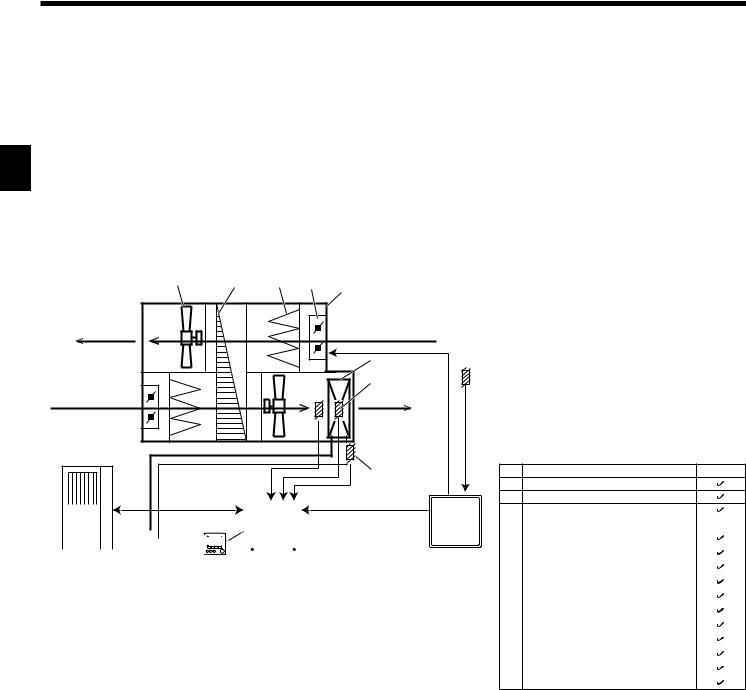
2.1. Check the parts (Fig. 2.1.1)
The interface unit should be supplied with the following parts. |
|
||
|
|
|
|
|
Part Name |
PAC-IF013B-E |
PAC-SIF013B-E |
1 |
Interface unit |
1 |
1 |
2 |
Thermistor |
4 |
4 |
3 |
Remote controller cable (5m) |
1 |
─ |
4 |
Remote controller |
1 |
─ |
2.2. Choosing the interface unit installation location
• Do not install the interface unit in outdoor location as it is designed for indoor |
EN |
|
|
installation only. (The interface board and casing are not waterproof.) |
|
• Avoid locations where the unit is exposed to direct sunlight or other sources of |
|
heat. |
|
• Select a location where easy wiring access to the power source is available. |
|
• Avoid locations where combustible gases may leak, be produced, flow, or accu- |
|
mulate. |
|
• Select a level location that can bear the weight and vibration of the unit. |
|
• Avoid locations where the unit is exposed to oil, steam, or sulfuric gas. |
|
• Do not install in location that is hot or humid for long period of time. |
|
2.3. Installing the interface unit (Fig. 2.3.1, 2.3.2, 2.3.3)
1.Remove 2 screws A from interface unit and remove the cover by sliding it upward (See Fig. 2.3.1).
2.Install the 4 screws (locally supplied) in 4 holes (C hole).
*To prevent the unit from falling off the wall, select the appropriate screws (locally supplied) and secure the base horizontally to the appropriate wall location. (See Fig. 2.3.2)
A Screw |
B Cover |
C Hole for installation |
|
|
|
|
|
|
|
PAC-IF013B-E |
PAC-SIF013B-E |
Weight |
|
2.5 kg + ACCESSORIES |
2.5 kg + ACCESSORIES |
|
0.8 kg |
0.4 kg |
|
|
|
||
Allowable ambient temperature |
0 to 35°C |
0 to 35°C |
|
Allowable ambient humidity |
80% RH or less |
80% RH or less |
|
|
336 |
|
|
|
|
(11.5) |
|
11.5 |
313 |
|
|
|
|
|
|
C |
|
|
|
|
|
C |
|
|
|
|
|
[ |
22 |
|
|
|
|
|
|
[ |
5 |
|
|
|
|
|
|
|
|
|
|
TB61 |
|
|
|
12 |
|
|
|
|
|
|
|
|
10 |
|
|
TB62 |
|
|
|
|
|
|
|
|
|
|
|
|
|
200 |
278 |
TB63 |
TB143 |
TB142 |
TB141 |
TB6 |
|
|
|
|
|
|
|
||||
C |
|
|
|
|
|
C |
|
3-ELECTRIC WIRE INLET
When install on a wall: Lower side
<Fig. 2.3.3>
Unit: mm
69 |
3
EN
3. System
Step mode (Input) |
Target temperature |
Number of outdoor unit |
Intelligent multiple outdoor unit control |
System |
|
|
|
|
|
Manual |
|
1 |
Not available |
See (1-1) below. |
|
─ |
2-6 |
Apply |
See (2-1) below. |
|
|
Not apply |
See (1-1) below.*1 |
|
|
|
|
||
Auto |
Supply air temp. control |
1-5 |
Not available |
See (1-2) below. |
|
Return air temp. control |
1-5 |
Not available |
See (1-3) below. |
*1. It is recommended to select Intelligent multiple outdoor unit control.
Design local AHU controller to make sure the following points.
•Minimum capacity request should be 20% or more of total capacity.
•Operate all outdoor units when outdoor temperature is below -15 °C.
3.1. System configuration (Single outdoor unit)
(1-1) Manual step mode *1 |
|
|
|
|
|
*1. Manual step mode: |
|
|
|
|
|
|
|
|
• Variable capacity request signals for heat pump need to be |
||
15 |
14 |
13 |
12 |
8 |
|
calculated by AHU local controller. |
|
|
|
|
• AHU local controller can send “Capacity steps” by non- |
||||||
Exhaust Air |
|
|
|
|
|
voltage contact signals or analog signals to the interface |
||
|
|
|
Return Air |
|
unit. |
|
|
|
(E.A.) |
|
|
|
(R.A.) |
|
• Operation mode can be set by remote controller, external |
||
|
|
|
|
input or DIP switch. |
|
|||
|
|
|
|
|
|
|
||
|
|
|
|
10 |
11 |
Note |
|
|
|
|
|
|
• Do NOT select STEP 0 for 3 minutes after compressor is |
||||
|
|
|
|
6 |
|
ON. (Keep compressor ON for 3 minutes at least.) |
||
|
|
|
7 |
|
• When changing STEP, make it less than 5 steps in a single |
|||
|
|
|
|
|
||||
|
|
|
|
|
request, and keep at least 5 minutes interval between the |
|||
Outdoor Air |
|
|
|
Supply Air |
|
changes. |
|
|
|
|
|
|
• Keep operation range shown at the following section 3.3. |
||||
(O.A.) |
|
|
|
(S.A.) |
|
• Do NOT send STEP 0 during defrost operation. |
||
|
|
|
|
|
|
• Do NOT change operation mode frequently. |
|
|
|
|
|
|
5 |
|
No. |
Part name |
System (1-1) |
|
|
|
|
|
|
1 |
Interface unit |
|
|
|
|
|
|
|
2 |
Remote controller |
|
|
|
|
|
|
|
|
|
|
|
|
|
|
|
|
|
|
|
|
9 |
3 |
Outdoor unit |
|
|
|
|
|
|
|
|
|
|
|
|
|
|
|
|
|
|
|
|
4 |
Target air temp. thermistor (TH1) |
─ *2 |
|
|
|
|
|
|
|
|
|
|
|
|
|
|
|
|
|
|
|
|
|
|
|
|
|
|
|
|
|
|
|
|
|
|
|
|
|
|
|
|
|
|
|
|
5 |
Ref. liquid temp. thermistor (TH2) |
|
|
|
|
|
|
|
|
|
|
|
|
|
|
|
|
|
|
|
|
|
|
||
|
|
|
|
|
|
|
|
|
|
|
|
|
|
|
|
|
|
|
|
6 |
2-Phase temp. thermistor (TH5) |
*3 |
|
|
|
|
|
|
|
|
|
|
|
|
|
|
|
|
|
|
|
|
|||
3 |
|
|
2 |
1 |
|
|
||||||||||||||||
|
|
|
|
7 |
HEX inlet (Coil on) temp. thermistor (TH11) |
|
||||||||||||||||
|
|
|
|
|
|
|
|
|
|
|
|
|
|
|
<Fig. 3.1.1> |
|
||||||
|
|
|
|
|
|
|
|
|
|
|
|
|
|
|
8 |
Air-Handling Unit (AHU) (Local supply) |
|
|||||
|
|
|
|
|
|
|
|
|
|
|
|
|
|
|
|
|
|
|
|
|
||
|
|
|
|
|
|
|
|
|
|
|
|
|
|
|
|
|
|
|
|
9 |
AHU local controller (Local supply) |
|
|
|
|
|
|
|
|
|
|
|
|
|
|
|
|
|
|
|
|
|
10 |
Heat exchanger of AHU (Local supply) |
|
|
|
|
|
|
|
|
|
|
|
|
|
|
|
|
|
|
|
|
|
11 |
Target air temp. thermistor (Local supply) |
|
|
|
|
|
|
|
|
|
|
|
|
|
|
|
|
|
|
|
|
|
12 |
Louver (Local supply) |
|
|
|
|
|
|
|
|
|
|
|
|
|
|
|
|
|
|
|
|
|
13 |
Air filter (Local supply) |
|
|
|
|
|
|
|
|
|
|
|
|
|
|
|
|
|
|
|
|
|
14 |
Heat recovery (Local supply) |
|
|
|
|
|
|
|
|
|
|
|
|
|
|
|
|
|
|
|
|
|
15 |
Fan (Local supply) |
|
*2. Set the DIP SW 2-8 to ON.
*3. If outdoor unit is SHW series, It’s not needed to install this thermistor, and set the DIP SW 1-5 to ON.
4

3. System
(1-2) Auto step mode *4 & Supply air temp. control |
*4. Auto step mode: |
|
• In this mode, the capacity step of the outdoor unit is con- |
15 |
14 |
13 |
12 |
8 |
|
trolled automatically to let the target temperature reach the |
||
|
|
set temperature. |
|
|||||
Exhaust Air |
|
|
|
Return Air |
|
Note |
|
|
(E.A.) |
|
|
|
(R.A.) |
|
• Auto change over function between cooling and heating |
||
|
|
|
|
|
|
mode is NOT available in this system. |
|
|
|
|
|
|
10 |
|
• Keep operation range shown at the following section 3.3. |
||
|
|
|
|
|
|
• Standard setting of DIP SW3-4 and SW3-5 is 3°C |
||
|
|
|
|
6 |
|
(SW3-4 : ON , SW3-5 : OFF). |
|
|
|
|
|
7 |
|
4 |
(Refer to “4.1.7 Switch setting”.) |
|
|
|
|
|
|
|
|
|
||
Outdoor Air |
|
|
|
Supply Air |
|
|
|
|
(O.A.) |
|
|
|
(S.A.) |
|
No. |
Part name |
System (1-2) |
|
|
|
|
|
|
1 |
Interface unit |
|
|
|
|
|
5 |
|
2 |
Remote controller |
|
|
|
|
|
|
3 |
Outdoor unit |
|
|
|
|
|
|
|
|
4 |
Target air temp. thermistor (TH1) |
|
5 Ref. liquid temp. thermistor (TH2)
|
|
|
|
|
|
|
|
|
|
|
|
|
|
|
|
|
|
|
|
|
9 |
6 |
2-Phase temp. thermistor (TH5) |
*5 |
|
|
|
|
|
|
|
|
|
|
|
|
|
|
|
|
|
|
|
|
|
||||
|
|
|
|
|
|
|
|
|
|
|
|
|
|
|
|
|
|
|
|
|
7 |
HEX inlet (Coil on) temp. thermistor (TH11) |
|
|
|
|
|
|
|
|
|
|
|
|
|
|
|
|
|
|
|
|
|
|
|
|
|
||
|
|
|
|
|
|
|
|
|
|
|
|
|
|
|
|
|
|
|
|
|
|
8 |
Air-Handling Unit (AHU) (Local supply) |
|
|
|
|
|
|
|
|
|
|
|
|
|
|
|
|
|
|
|
|
|
|
|
|
||
|
|
|
|
|
|
|
|
|
|
|
|
|
|
|
|
|
|
|
|
|
|
|
|
|
|
|
|
|
|
|
|
|
|
|
|
|
|
|
|
|
|
|
|
|
9 |
AHU local controller (Local supply) |
|
||
3 |
|
|
2 |
1 |
|
|
|
|||||||||||||||||
|
10 |
Heat exchanger of AHU (Local supply) |
|
|||||||||||||||||||||
|
|
|
|
|
|
|
|
|
|
|
|
|
|
|
|
|
<Fig. 3.1.2> |
|
|
|||||
|
|
|
|
|
|
|
|
|
|
|
|
|
|
|
|
|
|
11 |
Target air temp. thermistor (Local supply) |
─ |
||||
|
|
|
|
|
|
|
|
|
|
|
|
|
|
|
|
|
|
|
|
|
|
|||
|
|
|
|
|
|
|
|
|
|
|
|
|
|
|
|
|
|
|
|
|
|
12 |
Louver (Local supply) |
|
|
|
|
|
|
|
|
|
|
|
|
|
|
|
|
|
|
|
|
|
|
|
13 |
Air filter (Local supply) |
|
|
|
|
|
|
|
|
|
|
|
|
|
|
|
|
|
|
|
|
|
|
|
14 |
Heat recovery (Local supply) |
|
|
|
|
|
|
|
|
|
|
|
|
|
|
|
|
|
|
|
|
|
|
|
15 |
Fan (Local supply) |
|
*5. If outdoor unit is SHW series, It’s not needed to install this thermistor, and set the DIP SW 1-5 to ON.
EN
(1-3) Auto step mode *6 & Return/ Room air temp. control *7 |
|
*6. Auto step mode: |
|
|||||
|
|
|
|
|
|
• In this mode, the capacity step of the outdoor unit is con- |
||
15 |
14 |
13 |
12 |
8 |
|
trolled automatically to let the target temperature reach the |
||
|
set temperature. |
|
||||||
|
|
|
|
|
|
*7. Return/Room air temp. control: |
|
|
Exhaust Air |
|
|
|
Return Air |
|
• Set the DIP SW 1-7 to ON. |
|
|
|
|
|
4 |
Note |
|
|
||
(E.A.) |
|
|
|
(R.A.) |
|
|
||
|
|
|
|
• Auto change over function between cooling and heating |
||||
|
|
|
|
|
|
mode is available ONLY when this system is selected and |
||
|
|
|
|
10 |
|
the input selection of capacity setting (DIP SW1 and SW6) |
||
|
|
|
|
|
is ″No input (Auto step mode)″. |
|
||
|
|
|
|
6 |
|
• Keep operation range shown at the following section 3.3. |
||
|
|
|
7 |
|
No. |
Part name |
System (1-3) |
|
|
|
|
|
|
||||
Outdoor Air |
|
|
|
|
|
1 |
Interface unit |
|
|
|
|
Supply Air |
|
2 |
Remote controller |
|
|
(O.A.) |
|
|
|
|
3 |
Outdoor unit |
|
|
|
|
|
(S.A.) |
|
|
|||
|
|
|
|
|
4 |
Target air temp. thermistor (TH1) |
|
|
|
|
|
|
|
|
|
||
|
|
|
|
5 |
|
5 |
Ref. liquid temp. thermistor (TH2) |
|
|
|
|
|
|
6 |
2-Phase temp. thermistor (TH5) |
*8 |
|
7 HEX inlet (Coil on) temp. thermistor (TH11)
|
|
|
|
8 |
Air-Handling Unit (AHU) (Local supply) |
|
|
|
|
9 |
9 |
AHU local controller (Local supply) |
|
|
|
|
10 |
Heat exchanger of AHU (Local supply) |
|
|
|
|
|
|
|
||
|
|
|
|
11 |
Target air temp. thermistor (Local supply) |
─ |
3 |
2 |
1 |
|
12 |
Louver (Local supply) |
|
|
13 |
Air filter (Local supply) |
|
|||
|
|
<Fig. 3.1.3> |
|
|
||
|
|
|
14 |
Heat recovery (Local supply) |
|
|
|
|
|
|
|
||
|
|
|
|
15 |
Fan (Local supply) |
|
*8. If outdoor unit is SHW series, It’s not needed to install this thermistor, and set the DIP SW 1-5 to ON.
5

3. System
3.2.System configuration
(Intelligent multiple outdoor unit control *1)
(2-1) Manual step mode (example) |
|
|
|
|
|
15 |
14 |
13 |
12 |
8 |
|
|
|
||||
Exhaust Air |
|
|
|
Return Air |
|
(E.A.) |
|
|
|
(R.A.) |
|
EN |
|
|
|
10 |
|
|
|
|
|
|
|
|
|
|
7 |
6 |
11 |
|
|
|
|
|
|
Outdoor Air |
|
|
|
Supply Air |
|
(O.A.) |
|
|
|
(S.A.) |
|
|
|
|
|
5 |
|
9
|
|
|
|
|
|
|
|
|
|
|
|
|
|
|
|
3(Ref. adress: 0) |
1(Main) |
||||||||||||||
|
|
|
|
|
|
|
|
|
|
|
|
|
|
|
|
|
|
|
|
|
|
|
|
|
|
|
|
|
|
|
|
|
|
|
|
|
|
|
|
|
|
|
|
|
|
|
|
|
|
|
|
|
|
|
|
|
|
|
|
|
|
|
|
|
|
|
|
|
|
|
|
|
|
|
|
|
|
|
|
|
|
|
|
|
|
|
|
|
|
|
|
|
|
|
|
3(Ref. adress: 1) |
2 |
1(Sub) |
<Fig. 3.2.1>
*1. Interface system receives step request signal correspond to total capacity of outdoor units, and calculates necessary capacity for each outdoor unit automatically.
Note
•This intelligent multiple outdoor unit control function is available only when Manual step mode is selected.
•Up to 6 outdoor units can be connected.
•2 different type of outdoor units (capacity and/or series) can be mixed,but connecting the same capacity outdoor units is highly recommended.
•Ref. address setting on each outdoor unit is needed.
•Interface unit which connects to the Ref. address 0 outdoor unit, becomes main interface unit.
•Connect AHU local controller (Part No. 9) to the main interface unit.
•Connect ONE remote controller (Part No. 2) to the interface unit.
•Connect between the interface units with a remote controller (daisy chain). MAX. : 500m
•When using this function, set the DIP SW 1-8 of all interface unit to ON.
•Do NOT select STEP 0 for 3 minutes after compressor is ON. (Keep compressor ON for 3 minutes at least.)
•When changing STEP, make it less than 5 steps in a single operation, and keep at least 5 minutes interval between the changes.
•Keep operation range shown at the following section 3.3.
•Do NOT send STEP 0 during defrost operation.
•Do NOT change operation mode frequently.
No. |
Part name |
System (2-1) |
1 |
Interface unit |
|
2 |
Remote controller |
|
3 |
Outdoor unit |
|
4 |
Target air temp. thermistor (TH1) |
─ *2 |
5 |
Ref. liquid temp. thermistor (TH2) |
|
6 |
2-Phase temp. thermistor (TH5) |
*3 |
7 |
HEX inlet (Coil on) temp. thermistor (TH11) |
|
8 |
Air-Handling Unit (AHU) (Local supply) |
|
9 |
AHU local controller (Local supply) |
|
10 |
Heat exchanger of AHU (Local supply) |
|
11 |
Target air temp. thermistor (Local supply) |
|
12 |
Louver (Local supply) |
|
13 |
Air filter (Local supply) |
|
14 |
Heat recovery (Local supply) |
|
15 |
Fan (Local supply) |
|
*2. Set the DIP SW 2-8 to ON.
*3. If outdoor unit is SHW series, It’s not needed to install this thermistor, and set the DIP SW 1-5 to ON.
3.3. Indoor operation range
Mode |
Number of outdoor unit |
HEX inlet air temp. operation range |
|
|
|
|
|
Cooling |
1 or more |
15 - 32 °C |
|
|
|
|
|
Heating |
1 |
0 - 28 °C |
|
|
|
||
2 or more |
5 - 28 °C |
||
|
|||
|
|
|
6

4. Electrical work
4.1. Electrical connection
All electrical work should be carried out by a suitably qualified technician. Failure to comply with this could lead to electrocution, fire, and death. All wiring should be according to national wiring regulations.
Connections should be made to the terminals indicated in the following figures.
Use ring terminals and insulate the wires.
Tighten the screw from the bottom terminals first.
Notes:
1.Do not run the low voltage cables through a slot that the high voltage cables go through.
2.Do not bundle power cables together with other cables.
3.Bundle cables as Fig. 4.1.1 by using clamps.
|
|
EN |
|
INPUT |
OUTPUT |
Power cables |
|
Remote controller |
|||
|
|
||
thermistor |
<Fig. 4.1.1> |
||
|
|||
4.1.1. Interface unit power supplied from outdoor unit
The following connection patterns are available.
The outdoor unit power supply patterns vary on models.
|
|
|
D |
F |
A |
B |
C |
L |
|
N |
|
|||
|
|
TB6 |
||
|
|
|
|
|
|
|
|
S1 |
S1 |
|
|
|
S2 |
S2 |
|
|
|
S3 |
S3 |
E
Note:
AOutdoor unit power supply
BEarth leakage breaker *1, *2
CWiring circuit breaker or isolating switch
D Outdoor unit
EInterface unit/outdoor unit connecting cables
FInterface unit
*1 If the installed earth leakage circuit breaker does not have a function to protect over-current, install a breaker with that function along the same power line.
*2. A breaker with at least 3.0 mm contact separation in each pole shall be provided. Use earth leakage breaker (NV).
The breaker shall be provided to ensure disconnection of all active phase conductors of the supply.
In accordance with IEE regulations the circuit breaker/isolating switch located on the outdoor unit should be installed with lockable devices (health and safety).
Wiring Wire No. × size (mm²) |
Interface unit - Outdoor unit |
*3 |
3 × 1.5 (polar) |
|
|
|
|
Interface unit - Outdoor unit earth |
*3 |
1 × Min. 1.5 |
|
|
|
|
|
Circuit rating |
Interface unit - Outdoor unit S1-S2 |
*4 |
230 V AC |
|
|
|
|
Interface unit - Outdoor unit S2-S3 |
*4 |
24 V DC |
|
|
|
|
|
Notes: 1. Wiring size must comply with the applicable local and national code.
*3. Max. 45 m
If 2.5 mm² used, Max. 50 m
If 2.5 mm² used and S3 separated, Max. 80 m
*4.The values given in the left table are not always measured against the ground value.
2.Interface unit/outdoor unit connecting cords shall not be lighter than polychloroprene sheathed flexible cord. (Design 60245 IEC 57) Interface unit power supply cords shall not be lighter than polychloroprene sheathed flexible cord. (Design 60227 IEC 53)
3.Install an earth longer than other cables.
4.1.2.Separate interface unit/outdoor unit power supplies
The following connection patterns are available.
The outdoor unit power supply patterns vary on models.
D
A |
B C |
L |
G |
B |
C |
|
N |
||||||
|
|
|
S1
S2
S3 E
F
TB6
L
N
S1
S2
S3
AOutdoor unit power supply
BEarth leakage breaker *1, *2
CWiring circuit breaker or isolating switch
D Outdoor unit
EInterface unit/outdoor unit connecting cables
FInterface unit
GInterface unit power supply
*1 If the installed earth leakage circuit breaker does not have a function to protect over-current, install a breaker with that function along the same power line.
Note:
In accordance with IEE regulations the circuit breaker/isolating switch located on the outdoor unit should be installed with lockable devices (health and safety).
If the interface and outdoor units have separate power supplies, refer to the table below.
|
Separate power supply specifications |
|
|||||
Interface unit controller connector |
|
|
Disconnected |
|
CNS2 |
||
(CNS2) connection change |
|
|
|
|
|
|
|
Outdoor unit DIP switch settings (when |
|
|
|
|
|
|
|
|
ON |
|
|
3 |
|
|
|
using separate interface unit/outdoor |
|
|
|
|
|
||
|
OFF |
1 |
2 |
|
(SW8) |
|
|
unit power supplies only) |
|
|
|
||||
Set the SW8-3 to ON. |
|
|
|||||
|
|
|
|||||
|
|
|
|
|
|
|
|
<Photo 4.1.2>
7
4. Electrical work
EN
Interface unit power supply |
|
~/N 230 V 50 Hz |
||
Interface unit input capacity |
*2 |
16 A |
||
Main switch (Breaker) |
|
|||
|
|
|||
× |
Interface unit power supply |
|
2 × Min. 1.5 |
|
Wiring Wire No. size (mm²) |
Interface unit power supply earth |
|
1 × Min. 1.5 |
|
Interface unit-Outdoor unit |
*3 |
2 × Min. 0.3 |
||
Interface unit-Outdoor unit earth |
|
— |
||
|
|
|||
Circuit rating |
Interface unit L-N |
*4 |
230 V AC |
|
Interface unit-Outdoor unit S1-S2 |
*4 |
— |
||
Interface unit-Outdoor unit S2-S3 |
*4 |
24 V DC |
||
|
||||
Notes: 1. Wiring size must comply with the applicable local and national code.
*2. A breaker with at least 3.0 mm contact separation in each pole shall be provided. Use earth leakage breaker (NV).
The breaker shall be provided to ensure disconnection of all active phase conductors of the supply.
*3. Max. 120 m
*4. The values given in the left table are not always measured against the ground value.
2.Interface unit/outdoor unit connecting cords shall not be lighter than polychloroprene sheathed flexible cord. (Design 60245 IEC 57) Interface unit power supply cords shall not be lighter than polychloroprene sheathed flexible cord. (Design 60227 IEC 53)
3.Install an earth longer than other cables.
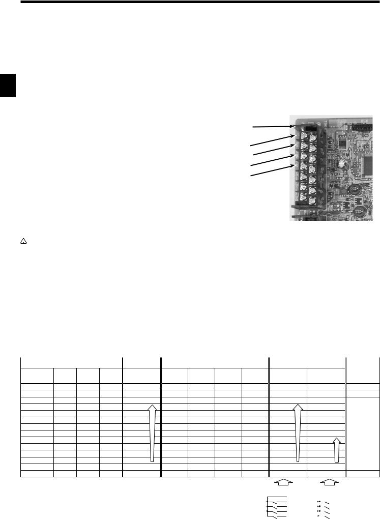
4.1.3.Connecting thermistor cable
Connect the thermistor 2 for the interface controller.
1.Target temp. thermistor (TH1)
Connect the thermistor for the target temp. to 1 and 2 on the terminal block (TB61)
on the interface controller.
2. HEX inlet temp. thermistor (TH11)
Connect the thermistor for the HEX inlet temp. to 3 and 4 on the terminal block (TB61) on the interface controller.
3. Ref. liquid temp. thermistor (TH2)
Connect the thermistor for the ref. liquid temp. to 5 and 6 on the terminal block (TB61) on the interface controller.
4.2-phase temp. thermistor (TH5)
Connect the thermistor for the 2-phase temp. to 7 and 8 on the terminal block
(TB61) on the interface controller. |
|
When the thermistor cables are too long, cut it to the appropriate length. |
|
Do not bind it in the interface unit. |
|
The 4 thermistors have the same specification except the color of cables, thus we do not specify which thermistor should be |
<Photo 4.1.3> |
installed to which position. |
|
Notes: When multiple outdoor units are connected, conect thermistors to each interface unit respectively. |
|
 Caution:
Do not route the thermistor cables together with power cables.
The sensor part of the thermistor should be installed where user can not access. (It should be separated by the supplementary insulation from areas the user can access.)
4.1.4. Connecting external input
Demand control is available by external input.
Select input type by setting the switch of the interface controller, and it is possible to set capacity request when manual step mode (“Analog input” , “Remote switch” or “Modbus”) is selected. Switch1, Switch 6 : Input selection of inverter capacity setting
Input |
SW 1-1 |
SW 1-2 |
SW 1-3 |
SW 6-1 |
SW 6-2 |
Step for capacity setting |
|
|
|
|
|
|
|
|
|
REMOTE SWITCH Type A (4bit-8 setting) |
OFF |
OFF |
OFF |
OFF |
OFF |
|
|
REMOTE SWITCHType B (1bit-1 setting) |
ON |
OFF |
OFF |
OFF |
OFF |
|
|
Analog (4-20mA) |
ON |
ON |
OFF |
ON |
ON |
See the "Capacity setting" table below. |
|
Analog (1-5V) |
ON |
ON |
OFF |
OFF |
ON |
||
|
|||||||
Analog (0-10V) |
OFF |
OFF |
ON |
OFF |
OFF |
|
|
Analog (0-10kΩ) |
ON |
OFF |
ON |
OFF |
OFF |
|
|
No input (Auto step mode) |
OFF |
ON |
ON |
OFF |
OFF |
Only Auto step mode |
|
Modbus |
ON |
ON |
ON |
OFF |
OFF |
OFF/Step1/Step2/…/Step11 |
• Capacity setting
Analog input |
Step for |
Remote switch |
Step for capacity setting |
|
capacity setting |
||||
|
|
|
Variable |
|
|
|
|
|
TB 62 |
TB 62 |
TB 62 |
TB 62 |
Remote SW |
Remote SW |
Remark |
||
resistor |
4-20mA |
1-5V |
0-10V |
Analog input |
10-11 |
10-12 |
10-13 |
10-14 |
|
|||||
(Type A) |
(Type B) |
|
||||||||||||
(0-10kΩ) |
|
|
|
|
|
(COM-IN5) |
(COM-IN6) (COM-IN7) (COM-IN8) |
|
||||||
|
|
|
|
|
|
|
|
|
|
|||||
OPEN(12kΩ-) |
– |
– |
– |
OFF |
|
– |
– |
– |
– |
|
– |
– |
|
Stop |
10kΩ |
– |
– |
– |
Auto |
|
OFF |
OFF |
OFF |
ON |
Auto |
|
Auto |
|
Auto step mode |
7.5kΩ |
19-20mA |
4.75-5V |
9.75-10V |
Step11 |
max. |
ON |
ON |
ON |
OFF |
Step11 |
max. |
– |
|
|
– |
– |
– |
9.02V |
Step10 |
|
– |
– |
– |
– |
|
– |
– |
|
|
5.6kΩ |
17mA |
4.25V |
8.20V |
Step9 |
|
OFF |
ON |
ON |
OFF |
Step9 |
|
– |
|
|
4.3kΩ |
15mA |
3.75V |
7.38V |
Step8 |
|
ON |
OFF |
ON |
OFF |
Step8 |
|
– |
|
|
– |
– |
– |
6.56V |
Step7 |
|
– |
– |
– |
– |
|
– |
– |
|
|
3.3kΩ |
13mA |
3.25V |
5.75V |
Step6 |
|
OFF |
OFF |
ON |
OFF |
Step6 |
|
Step11 |
max. |
Hz fixed mode |
– |
– |
– |
4.93V |
Step5 |
|
– |
– |
– |
– |
|
– |
– |
|
|
2kΩ |
11mA |
2.75V |
4.11V |
Step4 |
|
ON |
ON |
OFF |
OFF |
Step4 |
|
– |
|
|
1kΩ |
9mA |
2.25V |
3.29V |
Step3 |
|
OFF |
ON |
OFF |
OFF |
Step3 |
|
Step6 |
|
|
– |
– |
– |
2.47V |
Step2 |
|
– |
– |
– |
– |
|
– |
– |
|
|
510Ω |
7mA |
1.75V |
1.66V |
Step1 |
min. |
ON |
OFF |
OFF |
OFF |
Step1 |
min. |
Step1 |
min. |
|
0-100Ω |
4-5mA |
0-1.25V |
0-0.63V |
OFF |
|
OFF |
OFF |
OFF |
OFF |
OFF |
|
OFF |
|
Stop |
At site |
|
I/F |
||
|
{ |
|
14 |
|
|
|
|
10 |
|
|
|
|
11 |
|
OFF – AUTO |
|
|
12 |
|
|
|
13 |
|
|
|
|
|
|
|
8 |
|
|
|
|
|
|
TB62 |
||
|
||||
At site |
|
|
|
|
|
I/F |
||||
|
|
|
|
|
|
|
|
|
10 |
|
Step1 |
|
|
|
|
|
|
|
|
11 |
|
Step6 |
|
|
|
|
|
|
12 |
|
||
|
|
|
|
|
|
|
|
|
||
Step11 |
|
|
|
|
|
|
|
13 |
|
|
|
|
|
|
|
|
|||||
AUTO |
|
|
|
|
|
|
|
14 |
|
|
|
|
|
|
|
|
|
|
|
TB62 |
|
 Loading...