


Split-type Air-Conditioner
MXZ-3D54VA
MXZ-3D68VA
MXZ-4D72VA
English is original.
Übersetzung des Originals
Traduction du texte d’origine
Installation Manual |
For INSTALLER |
•This manual only describes the installation of outdoor unit.
When installing the indoor unit, refer to the installation manual of indoor unit.
Installationsanleitung |
Für INSTALLATEUR |
•Diese Installationsanleitung gilt nur für die Installation des Außengerätes.
Zur Installation des Innengeräts siehe die Installationsanleitung für Innengeräte.
Notice d’installation |
Destinée à l’INSTALLATEUR |
•Cette notice ne décrit que l’installation de l’appareil extérieur.
Lors de l’installation de l’appareil intérieur, consultez la notice d’installation de cet appareil.
Vertaling van het |
Installatiehandleiding |
Voor de INSTALLATEUR |
origineel |
• Deze handleiding beschrijft alleen de installatie van de buitenunit. |
|
Raadpleeg de installatiehandleiding van de binnenunit wanneer u deze installeert.
Traducción del original
Traduzione dell’originale
Μετάφραση του αρχικού
Tradução do original
Oversættelse af den originale tekst
Översättning från originalet
Orijinalin çevirisi
Перевод
оригинала
Manual de instalación |
Para el INSTALADOR |
•En este manual sólo se describe la instalación de la unidad exterior.
Para instalar la unidad interior, consulte el manual de instalación de dicha unidad.
Manuale per l’installazione |
Per il TECNICO INSTALLATORE |
•Questo manuale descrive solo l’installazione dell’unità esterna.
Per l’installazione dell’unità interna, fare riferimento al relativo manuale di installazione.
Εγχειρίδιο εγκατάστασης |
Για τον ΤΕΧΝΙΚΟ |
•Στο παρόν εγχειρίδιο περιγράφεται μόνο η εγκατάσταση της μονάδας εξωτερικού χώρου. Για την εγκατάσταση της μονάδας εσωτερικού χώρου, ανατρέξτε στο εγχειρίδιο εγκατάστασης της μονάδας εσωτερικού χώρου.
Manual de Instalação |
Para o INSTALADOR |
•Este manual descreve apenas a instalação da unidade exterior.
Quando proceder à instalação da unidade interior, consulte o manual de instalação da unidade interior.
Installationshåndbog |
Til INSTALLATØREN |
•Denne håndbog beskriver kun, hvordan udendørsenheden installeres. Vedrørende installation af indendørsenheden henvises til installationshåndbogen for indendørsenheden.
Installationsanvisning |
För INSTALLATÖREN |
•Denna installationsanvisning beskriver endast installation av utomhusenheten. Se den separata installationsanvisningen för inomhusenheten.
Kurulum Kılavuzu |
TESİSATÇI İÇİN |
•Bu kılavuzda yalnızca dış ünitenin kurulumu açıklanmaktadır.
İç ünite kurulum işlemini yaparken iç ünite kurulum kılavuzuna bakın.
Руководство по установке |
Для МОНТАЖНИКА |
•В данном руководстве приводится описание установки только наружного прибора. При установке внутреннего прибора см. руководство по установке внутреннего
прибора.
English
Deutsch
Français
Nederlands
Español
Italiano
Ελληνικά
Português
Dansk
Svenska
Türkçe
Русский
<![endif]>ENGLISH
CONTENTS |
|
|
1. |
BEFORE INSTALLATION............................................................. |
1 |
2. |
OUTDOOR UNIT INSTALLATION................................................ |
4 |
3. |
FLARING WORK AND PIPE CONNECTION............................... |
4 |
4. |
PURGING PROCEDURES, LEAK TEST, AND TEST RUN......... |
5 |
5. |
RELOCATION AND MAINTENANCE........................................... |
6 |
Required Tools for Installation
Phillips screwdriver |
Flare tool for R410A |
Level |
Gauge manifold for R410A |
Scale |
Vacuum pump for R410A |
Utility knife or scissors |
Charge hose for R410A |
Torque wrench |
Pipe cutter with reamer |
Wrench (or spanner) |
|
4 mm hexagonal wrench |
|
1. BEFORE INSTALLATION
1-1. THE FOLLOWING SHOULD ALWAYS BE OBSERVED FOR SAFETY
•Be sure to read “THE FOLLOWING SHOULD ALWAYS BE OBSERVED FOR SAFETY” before installing the air conditioner.
•Be sure to observe the warnings and cautions specified here as they include important items related to safety.
•After reading this manual, be sure to keep it together with the OPERATING INSTRUCTIONS for future reference.
•Equipment complying with IEC/EN 61000-3-12.
 WARNING (Could lead to death, serious injury, etc.)
nDo not install the unit by yourself (user).
Incomplete installation could cause fire or electric shock, injury due to the unit falling, or leakage of water. Consult the dealer from whom you purchased the unit or a qualified installer.
nPerform the installation securely referring to the installation manual.
Incomplete installation could cause fire, electric shock, injury due to the unit falling, or leakage of water.
nWhen installing the unit, use appropriate protective equipment and tools for safety.
Failure to do so could cause injury.
nInstall the unit securely in a place which can bear the weight of the unit.
If the installation location cannot bear the weight of the unit, the unit could fall causing injury.
nElectrical work should be performed by a qualified, experienced electrician, according to the installation manual. Be sure to use an exclusive circuit. Do not connect other electrical appliances to the circuit.
If the capacity of the power circuit is insufficient or there is incomplete electrical work, it could result in a fire or an electric shock.
nDo not damage the wires by applying excessive pressure with parts or screws.
Damaged wires could cause fire or electric shock.
nBe sure to cut off the main power in case of setting up the indoor P.C. board or wiring works.
Failure to do so could cause electric shock.
nUse the specified wires to connect the indoor and outdoor units securely and attach the wires firmly to the terminal block connecting sections so the stress of the wires is not applied to the sections. Do not extend the wires, or use intermediate connection.
Incomplete connecting and securing could cause fire.
nDo not install the unit in a place where inflammable gas may leak.
If gas leaks and accumulates in the area around the unit, it could cause an explosion.
nDo not use intermediate connection of the power cord or the extension cord and do not connect many devices to one AC outlet.
It could cause a fire or an electric shock due to defective contact, defective insulation, exceeding the permissible current, etc.
nBe sure to use the parts provided or specified parts for the installation work.
The use of defective parts could cause an injury or leakage of water due to a fire, an electric shock, the unit falling, etc.
nWhen plugging the power supply plug into the outlet, make sure that there is no dust, clogging, or loose parts in both the outlet and the plug. Make sure that the power supply plug is pushed completely into the outlet.
If there is dust, clogging, or loose parts on the power supply plug or the outlet, it could cause electric shock or fire. If loose parts are found on the power supply plug, replace it.
nAttach the electrical cover to the indoor unit and the service panel to the outdoor unit securely.
If the electrical cover of the indoor unit and/or the service panel of the outdoor unit are not attached securely, it could result in a fire or an electric shock due to dust, water, etc.
nWhen installing, relocating, or servicing the unit, make sure that no substance other than the specified refrigerant (R410A) enters the refrigerant circuit.
Any presence of foreign substance such as air can cause abnormal pressure rise and may result in explosion or injury. The use of any refrigerant other than that specified for the system will cause mechanical failure, system malfunction, or unit breakdown. In the worst case, this could lead to a serious impediment to securing product safety.
nDo not discharge the refrigerant into the atmosphere. If refrigerant leaks during installation, ventilate the room.
If refrigerant comes in contact with a fire, harmful gas could be generated.
Refrigerant leakage may cause suffocation. Provide ventilation in accordance with EN378-1.
nCheck that the refrigerant gas does not leak after installation has been completed.
If refrigerant gas leaks indoors, and comes into contact with the flame of a fan heater, space heater, stove, etc., harmful substances will be generated.
nUse appropriate tools and piping materials for installation.
The pressure of R410A is 1.6 times more than R22. Not using appropriate tools or materials and incomplete installation could cause the pipes to burst or injury.
nWhen pumping down the refrigerant, stop the compressor before disconnecting the refrigerant pipes.
If the refrigerant pipes are disconnected while the compressor is running and the stop valve is open, air could be drawn in and the pressure in the refrigeration cycle could become abnormally high. This could cause the pipes to burst or injury.
nWhen installing the unit, securely connect the refrigerant pipes before starting the compressor.
If the compressor is started before the refrigerant pipes are connected and when the stop valve is open, air could be drawn in and the pressure in the refrigeration cycle could become abnormally high. This could cause the pipes to burst or injury.
nFasten a flare nut with a torque wrench as specified in this manual.
If fastened too tight, a flare nut may break after a long period and cause refrigerant leakage.
nThe unit shall be installed in accordance with national wiring regulations.
nEarth the unit correctly.
Do not connect the earth to a gas pipe, water pipe, lightning rod or telephone earth. Defective earthing could cause electric shock.
CAUTION |
(Could lead to serious injury in particular environments when operated incorrectly.) |
nInstall an earth leakage breaker depending on the installation place.
If an earth leakage breaker is not installed, it could cause electric shock.
nPerform the drainage/piping work securely according to the installation manual.
If there is defect in the drainage/piping work, water could drop from the unit, soaking and damaging household goods.
nDo not touch the air inlet or the aluminum fins of the outdoor unit.
This could cause injury.
nDo not install the outdoor unit where small animals may live.
If small animals enter and touch the electric parts inside the unit, it could cause a malfunction, smoke emission, or fire. Also, advise user to keep the area around the unit clean.
1-2. SPECIFICATIONS
|
Power supply *1 |
Wire specifications *2 |
|
Pipe length and height difference *3, *4, *5, *6, *7, *8 |
||||||
Model |
Rated |
Fre- |
Breaker |
Power supply |
Indoor/outdoor |
Max. pipe length |
Max. height |
Max. no. of bends |
Refrigerant adjust- |
|
|
Voltage |
quency |
capacity |
connecting wire |
per indoor unit / |
difference *9 |
per indoor unit / |
ment A *10 |
||
|
|
for multi-system |
for multi system |
|||||||
MXZ-3D54VA |
|
|
|
|
4-core |
|
25 m / 50 m |
|
25 / 50 |
|
MXZ-3D68VA |
230 V |
50 Hz |
25 A |
3-core 2.5 mm2 |
2 |
|
15 m |
|
20 g/m |
|
|
|
|
|
|
1.0/1.5 mm |
|
25 m / 60 m |
|
25 / 60 |
|
MXZ-4D72VA |
|
|
|
|
|
|
|
|||
|
|
|
|
|
|
|
|
|
|
|
*1 Connect to the power switch which has a gap of 3 mm or more when open to interrupt the source power phase. (When the power switch is shut off, it must interrupt all phases.)
*2 Use wires in conformity with design 60245 IEC 57. Use the indoor/outdoor connecting wire in conformity with the wire specifications specified in the installation manual of the indoor unit.
*3 Never use pipes with thickness less than specified. The pressure resistance will be insufficient.
*4 Use a copper pipe or a copper-alloy seamless pipe.
*5 Be careful not to crush or bend the pipe during pipe bending.
*6 Refrigerant pipe bending radius must be 100 mm or more.
*7 Insulation material : Heat resisting foam plastic 0.045 specific gravity
*8 Be sure to use the insulation of specified thickness. Excessive thickness may cause incorrect installation of the indoor unit and insufficient thickness may cause dew drippage.
*9 If the outdoor unit is installed higher than the indoor unit, max. height difference is reduced to 10 m.
*10 If pipe length exceeds 40 m, additional refrigerant (R410A) charge is required. (No additional charge is required for pipe length less than 40 m.) Additional refrigerant = A × (pipe length (m) - 40)
En-
1-3. SELECTING OPTIONAL DIFFERENT-DIAMETER JOINTS
If the diameter of connection pipe does not match the port size of outdoor unit, use optional different-diameter joints according to the following table.
|
|
|
|
(Unit: mm (inch)) |
|
|
|
|
|
|
|
|
Port size of outdoor unit |
Optional different-diameter joints (port size of outdoor unit → diameter of connection pipe) |
|||
MXZ- |
MXZ- |
MXZ- |
Liquid / Gas |
6.35 (1/4) → 9.52 (3/8) : PAC-493PI |
|
3D54VA |
3D68VA |
4D72VA |
9.52 (3/8) → 12.7 (1/2) : MAC-A454JP |
||
|
|||||
- |
A UNIT |
6.35 (1/4) / 12.7 (1/2) |
9.52 (3/8) → 15.88 (5/8) : PAC-SG76RJ |
||
12.7 (1/2) → 9.52 (3/8) : MAC-A455JP |
|||||
|
|
|
|
||
A - C UNIT |
B - D |
6.35 (1/4) / 9.52 (3/8) |
12.7 (1/2) → 15.88 (5/8) : MAC-A456JP |
||
UNIT |
Refer to the installation manual of indoor unit for the diameter of connection pipe of indoor unit. |
||||
|
|
|
|||
1-4. SELECTING THE INSTALLATION LOCATION
•Where it is not exposed to strong wind.
•Where airflow is good and dustless.
•Where rain or direct sunshine can be avoided as much as possible.
•Where neighbours are not annoyed by operation sound or hot air.
•Where rigid wall or support is available to prevent the increase of operation sound or vibration.
•Where there is no risk of combustible gas leakage.
•When installing the unit, be sure to secure the unit legs.
•Where it is at least 3 m away from the antenna of TV set or radio. Operation of the air conditioner may interfere with radio or TV reception in areas where reception is weak. An amplifier may be required for the affected device.
•Install the unit horizontally.
•Please install it in an area not affected by snowfall or blowing snow.
In areas with heavy snow, please install a canopy, a pedestal and/or some baffle boards.
Note:
It is advisable to make a piping loop near outdoor unit so as to reduce vibration transmitted from there.
Note:
When operating the air conditioner in low outside temperature, be sure to follow the instructions described below.
•Never install the outdoor unit in a place where its air inlet/outlet side may be exposed directly to wind.
•To prevent exposure to wind, install the outdoor unit with its air inlet side facing the wall.
•To prevent exposure to wind, it is recommended to install a baffle
board on the air outlet side of the outdoor unit.
Avoid the following places for installation where air conditioner trouble is liable to occur.
•Where flammable gas could leak.
•Where there is much machine oil.
•Where oil is splashed or where the area is filled with oily smoke (such as cooking areas and factories, in which the properties of plastic could be changed and damaged).
•Salty places such as the seaside.
•Where sulfide gas is generated such as a hot spring.
•Where there is high-frequency or wireless equipment.
•Where there is emission of high levels of VOCs, including phthalate compounds, formaldehyde, etc., which may cause chemical cracking.
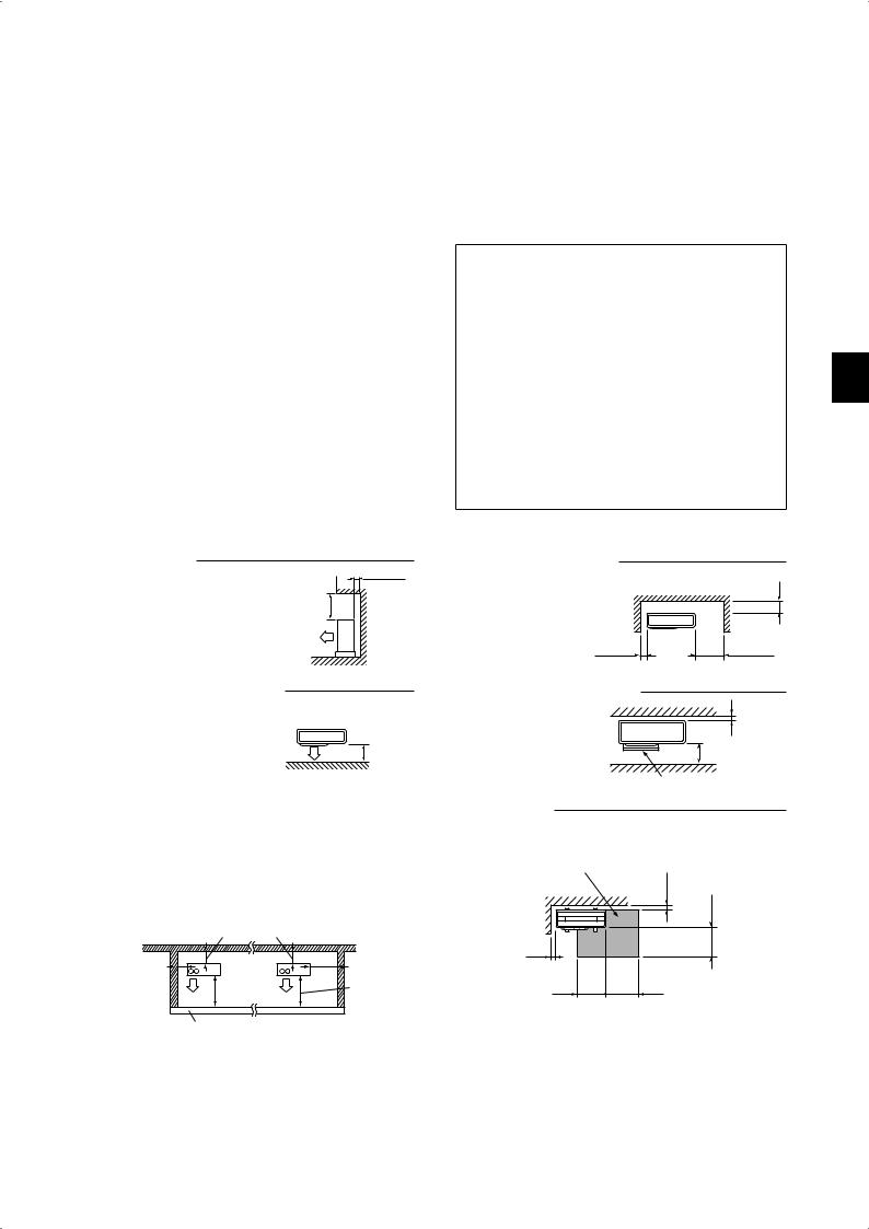
FREE SPACE REQUIRED AROUND OUTDOOR UNIT |
|
1. Obstacles above |
2. Front (blowing) side open |
When there is no obstacle in front |
100 or more |
As long as space indicated |
|
and on the sides of the unit, it is al- |
|
in the figure is provided, it |
200 or more |
lowed to install the unit where an |
500 or more |
is allowed to install the unit |
|
obstacle is above the unit only if the |
where obstacles are behind |
|
|
space shown in the figure is provided. |
|
and on the sides of the unit. |
|
|
|
(No obstacle above the unit) |
|
|
|
100 or more |
350 or more |
3.Obstacles in front (blowing) only
When there is an obstacle in front of the unit as shown in the figure, open space above, behind, and on the sides of the unit is required.
|
4. Obstacles in front and behind |
|
|
The unit can be used by at- |
|
|
taching an optional outdoor |
100 or more |
|
blowing guide (MAC-856SG) |
|
|
(but both sides and top are |
|
500 or more |
open). |
500 or more |
|
|
Blowing guide (MAC-856SG) |
5. Obstacles in front, behind and on side(s) |
|
6. Service space |
|
• When installing the unit in an area that is enclosed with walls such |
Provide space for service and maintenance as shown in the figure. |
||
as a verandah, be sure to have enough space as shown below. |
|
||
In this case, the air conditioning capacity and power consumption |
|
||
might deteriorate. |
|
Service space |
|
• When there is a lack of airflow or there is a possibility of becoming |
|||
|
|||
short cycle, install an outlet guide and make sure there is enough |
100 or more |
||
space behind of the unit. |
|
||
|
|
||
• When installing two or more units, do not install the units in front or |
|
||
behind each other. |
|
500 or more |
|
|
200 or more |
|
|
|
|
100 or more |
|
100 or more |
350 or more |
|
|
500 or more |
500 or more |
350 or more |
350 or more |
|
|
|
|
Height of the obstacle is 1200 or less |
|
|
(Unit: mm) |
|
|
|
En-
1-5. INSTALLATION DIAGRAM
Open as a rule More than 500 mm if the front and both sides are open
More than 100 mm
Open as a rule
More than 500 mm if the back, More than 350 mm both sides and top are open
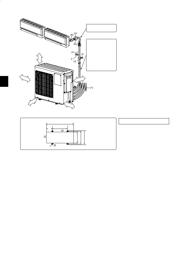
Outdoor unit installation
|
840 |
169 |
500 |
|
Air inlet |
After the leak test, apply insulating material tightly so that there is no gap.
When the piping is to be attached to a wall containing metals (tin plated) or metal netting, use a chemically treated wooden piece 20 mm or thicker between the wall and the piping or wrap 7 to 8 turns of insulation vinyl tape around the piping.
To use existing piping, perform COOL operation for 30 minutes and pump down before removing the old air conditioner. Remake flare according to the dimension for new refrigerant.
More than 100 mm
More than 200 mm if there are obstacles to both sides
Air inlet |
<![if ! IE]> <![endif]>330 |
<![if ! IE]> <![endif]>361 |
<![if ! IE]> <![endif]>396 |
|
|||
Air outlet |
|
|
(Unit: mm) |
4-10 × 21 Oval holes |
|
|
|
|
|
|
ACCESSORIES
Check the following parts before installation.
(1) |
Drain socket |
1 |
|
(2) |
Drain cap |
2 |
|
PARTS TO BE PROVIDED AT YOUR SITE |
|||
(A) |
Power supply cord* |
1 |
|
(B) |
Indoor/outdoor unit connecting wire* |
1 |
|
(C) |
Extension pipe |
1 |
|
(D) |
Wall hole cover |
1 |
|
(E) |
Piping tape |
1 |
|
|
Extension drain hose |
|
|
(F) |
(or soft PVC hose, 15 mm inner |
1 |
|
|
diameter or hard PVC pipe VP16) |
|
|
(G) |
Refrigeration oil |
Little |
|
amount |
|||
|
|
||
(H) |
Putty |
1 |
|
(I) |
Pipe fixing band |
2 to 7 |
|
(J) |
Fixing screw for (I) |
2 to 7 |
|
(K) |
Wall hole sleeve |
1 |
|
(L) |
Soft PVC hose, 15 mm inner di- |
1 |
|
ameter or hard PVC pipe VP16 for |
|||
|
drain socket (1) |
|
|
* Note:
Place indoor/outdoor unit connecting wire (B) and power supply cord (A) at least 1 m away from the TV antenna wire.
The “Q’ty” for (B) to (K) in the above table is quantity to be used per indoor unit.
Units should be installed by licensed contractor according to local code requirements.
1-6. DRAIN PIPING FOR OUTDOOR UNIT
Please perform the drain piping work only when draining from one place.
1)Choose one hole to discharge drain and install the drain socket (1) to the hole.
2)Close the rest of the holes with the drain caps (2).
3)Connect the soft PVC hose (L) of 15 mm in the inside diameter on the market with the drain socket (1) and lead drain.
Note:
Install the unit horizontally.
Do not use the drain socket (1) and the drain caps (2) in the cold regions. Drain may freeze and it makes the fan stop.
The outdoor unit produces condensate during the heating operation. Select the installation place to ensure to prevent the outdoor unit and/or the grounds from being wet by drain water or damaged by frozen drain water.
En-

2. OUTDOOR UNIT INSTALLATION
2-1. CONNECTING WIRES FOR OUTDOOR UNIT
1)Remove the service panel.
2)Loosen terminal screw, and connect indoor/outdoor unit connecting wire (B) from the indoor unit correctly on the terminal block. Be careful not to make mis-wiring. Fix the wire to the terminal block securely so that no part of its core is appeared, and no external force is conveyed to the connecting section of the terminal block.
3)Firmly tighten the terminal screws to prevent them from loosening. After tightening, pull the wires lightly to confirm that they do not move.
4)Perform 2) and 3) for each indoor unit.
5)Connect power supply cord (A).
6)Fix indoor/outdoor unit connecting wire (B) and power supply cord (A) with the cable clamps.
7)Close the service panel securely. Make sure that 3-2. PIPE CONNECTION is completed.
•After making connections between both power supply cord (A) and indoor/outdoor unit connecting wire (B), be sure to fix both cable and wire with cable clamps.
|
|
|
|
|
|
|
|
|
<OUTDOOR UNIT> |
|
|
|
|
|
|
|
|
|
|||||||
Indoor/outdoor unit |
|
|
|
|
|
|
|
|
|
|
|
|
|
|
|
|
|
|
|||||||
connecting wire |
|
|
|
|
|
|
|
|
|
Terminal block for |
|||||||||||||||
|
|
|
|
|
|
|
|
|
|
|
|
|
|
|
|
|
|||||||||
|
Terminal block |
|
|
Terminal block |
power supply |
||||||||||||||||||||
|
|
|
|
|
|
|
|
|
|
|
|
|
|
|
|
|
|
|
|
|
|
|
|
|
|
|
|
|
|
|
|
|
|
|
|
|
|
|
|
|
|
|
|
|
|
|
|
|
|
|
|
|
|
|
|
|
|
|
|
|
|
|
|
|
|
|
|
|
|
|
|
|
|
|
|
|
|
|
|
|
|
|
|
|
|
|
|
|
|
|
|
|
|
|
|
|
|
|
|
|
|
|
|
Terminal block |
Terminal block |
POWER SUPPLY |
|
|
~/N 230 V 50 Hz |
<INDOOR UNIT> D unit is for 4D72VA only
Terminal block for power supply
4D72VA |
Service panel
15 mm
35 mm
Lead wire
•Be sure to attach each screw to its correspondent terminal when securing the cord and/or the wire to the terminal block.
•Make earth wire a little longer than others. (More than 35 mm)
•For future servicing, give extra length to the connecting wires.
3. FLARING WORK AND PIPE CONNECTION
3-1. FLARING WORK
1)Cut the copper pipe correctly with pipe cutter. (Fig. 1, 2)
2)Completely remove all burrs from the cut cross section of pipe. (Fig. 3)
•Aim the copper pipe downward while removing burrs to prevent burrs from dropping in the pipe.
3)Remove flare nuts attached to indoor and outdoor units, then put them on pipe having completed burr removal. (Not possible to put them on after flaring work.)
4)Flaring work (Fig. 4, 5). Firmly hold copper pipe in the dimension shown in the table. Select A mm from the table according to the tool selected.
5)Check
•Compare the flared work with Fig. 6.
•If flare is noted to be defective, cut off the flared section and do flaring work again.
Pipe diameter |
Nut |
|
A (mm) |
|
Tightening torque |
||
Clutch |
Clutch |
Wing nut |
|
|
|||
(mm) |
(mm) |
type tool |
type tool |
type tool |
N•m |
kgf•cm |
|
|
|
for R410A |
for R22 |
for R22 |
|
|
|
ø6.35 (1/4”) |
17 |
|
|
1.5 to 2.0 |
13.7 to 17.7 |
140 to 180 |
|
ø9.52 (3/8”) |
22 |
0 to 0.5 |
1.0 to 1.5 |
34.3 to 41.2 |
350 to 420 |
||
|
|||||||
ø12.7 (1/2”) |
26 |
2.0 to 2.5 |
49.0 to 56.4 |
500 to 575 |
|||
|
|
||||||
ø15.88 (5/8”) |
29 |
|
|
73.5 to 78.4 |
750 to 800 |
||
|
|
|
|||||
3-2. PIPE CONNECTION
1)Apply a thin coat of refrigeration oil (G) to the flared ends of the pipes and the pipe connections of the outdoor unit. Do not apply refrigeration oil on screw threads. Excessive tightening torque will result in damage on the screw.
2)Align the center of the pipe with that of the pipe connections of the outdoor unit, then hand tighten the flare nut 3 to 4 turns.
3)Tighten the flare nut with a torque wrench as specified in the table.
•Over-tightening may cause damage to the flare nut, resulting in refrigerant leakage.
•Be sure to wrap insulation around the piping. Direct contact with the bare piping may result in burns or frostbite.
3-3. INSULATION AND TAPING
1)Cover piping joints with pipe cover.
2)For outdoor unit side, surely insulate every piping including valves.
3)Using piping tape (E), apply taping starting from the entry of outdoor unit.
•Stop the end of piping tape (E) with tape (with adhesive agent attached).
•When piping have to be arranged through above ceiling, closet or where the temperature and humidity are high, wind additional commercially sold insulation to prevent condensation.
|
Good |
No good |
|
Copper |
|
|
pipe |
|
|
Tilted Uneven Burred |
|
|
Fig. 1 |
Fig. 2 |
|
Flaring tool |
|
Burr |
Copper pipe |
|
|
Spare reamer |
|
|
Pipe cutter |
|
|
Clutch type |
Wing nut type |
|
Fig. 3 |
Fig. 4 |
|
|
Inside is shin- |
|
Smooth all |
ing without any |
|
around |
scratches. |
Die |
Copper pipe |
|
|
Even length |
|
|
|
|
Flare nut |
all around |
|
|
||
|
Fig. 5 |
Fig. 6 |
 WARNING
When installing the unit, securely connect the refrigerant pipes before starting the compressor.
 CAUTION
When there are the ports which are not used, make sure their nuts are tightened securely.
En-
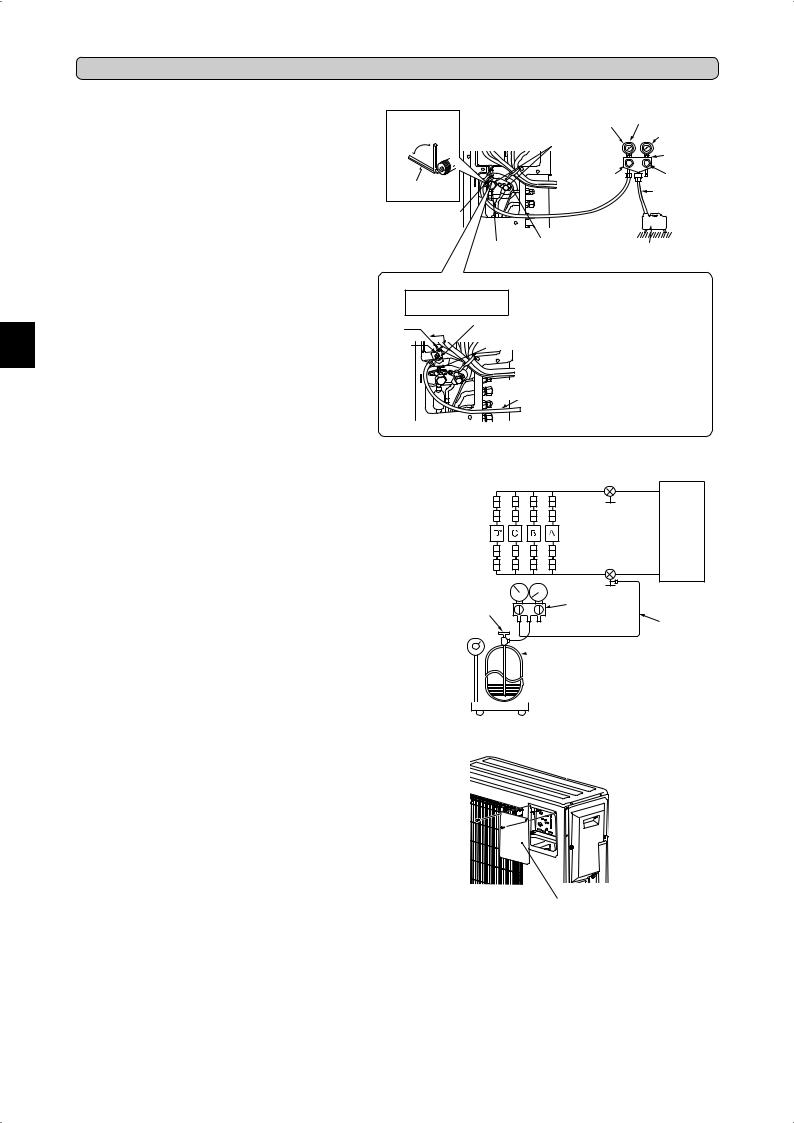
4. PURGING PROCEDURES, LEAK TEST, AND TEST RUN
4-1. PURGING PROCEDURES AND LEAK TEST
1)Remove service port cap of stop valve on the side of the outdoor unit gas pipe. (The stop valves are fully closed and covered in caps in their initial state.)
2)Connect gauge manifold valve and vacuum pump to service port of stop valve on the gas pipe side of the outdoor unit.
3)Run the vacuum pump. (Vacuumize for more than 15 minutes.)
4)Check the vacuum with gauge manifold valve, then close gauge manifold valve, and stop the vacuum pump.
5)Leave as it is for one or two minutes. Make sure the pointer of gauge manifold valve remains in the same position. Confirm that pressure gauge shows -0.101 MPa [Gauge] (-760 mmHg).
6)Remove gauge manifold valve quickly from service port of stop valve.
7)Fully open all stop valves on the gas pipe and the liquid pipe. Operating without fully opening lowers the performance and this causes trouble.
8)Refer to 1-2., and charge the prescribed amount of refrigerant if needed. Be sure to charge slowly with liquid refrigerant. Otherwise, composition of the refrigerant in the system may be changed and affect performance of the air conditioner.
9)Tighten cap of service port to obtain the initial status.
10)Leak test
*4 to 5 turns
*Close
*Open
Hexagonal wrench
Service port cap (Torque 13.7 to 17.7 N•m, 140 to
180 kgf•cm)
|
|
–0.101MPa |
Compound pressure |
|
Stop valve cap |
gauge (for R410A) |
|||
(Torque 19.6 to |
(–760 mmHg) |
|||
29.4 N•m, 200 |
|
Pressure gauge |
||
to 300 kgf•cm) |
|
(for R410A) |
||
|
|
|
Gauge manifold |
|
|
|
|
valve (for R410A) |
|
|
|
Handle |
Handle High |
|
|
|
Low |
Charge hose |
|
|
|
|
||
|
|
|
(for R410A) |
|
Stop valve |
Stop valve |
|
Vacuum pump |
|
for LIQUID |
||||
for GAS |
(for R410A) |
|||
|
|
|||
|
Precautions when using |
|
|
the control valve |
|
A |
Close |
Body |
Open |
||
Control |
Service port |
|
valve |
|
|
|
|
|
Charge hose (for R410A)
When attaching the control valve to the service port, valve core may deform or loosen if excess pressure is applied. This may cause gas leak.
When attaching the control valve to the service port, make sure that the valve core is in closed position, and then tighten part A. Do not tighten part A or turn the body when valve core is in open position.
4-2. GAS CHARGE
Perform gas charge to unit.
1)Connect gas cylinder to the service port of stop valve.
2)Perform air purge of the pipe (or hose) coming from refrigerant gas cylinder.
3)Replenish specified amount of the refrigerant, while operating the air conditioner for cooling.
Note:
In case of adding refrigerant, comply with the quantity specified for the refrigerating cycle.
CAUTION:
When charging the refrigerant system with additional refrigerant, be sure to use liquid refrigerant. Adding gas refrigerant may change the composition of the refrigerant in the system and affect normal operation of the air conditioner. Also, charge the liquid refrigerant slowly, otherwise the compressor will be locked.
To maintain the high pressure of the gas cylinder, warm the gas cylinder with warm water (under 40°C) during cold season. But never use naked fire or steam.
Union
Union
Union
Union
Refrigerant gas cylinder operating valve (for R410A)
Stop valve |
|
|
|
Liquid |
|
|
pipe |
|
Indoor |
Outdoor |
|
unit |
unit |
|
Stop valve with |
Gas |
|
service port |
||
pipe |
||
|
||
|
* D unit is for |
|
Gauge manifold |
4D72VA only. |
|
|
||
valve (for R410A) |
||
|
Charge hose |
|
|
(for R410A) |
|
 Refrigerant gas cylinder for R410A with siphon

 Refrigerant (liquid)

 Electronic scale for refrigerant charging
4-3. REMOVING THE MAINTENANCE PANEL
The setting of Dip Switch on the outdoor controller board can be changed without removing the front panel.
Follow the procedures below to remove the maintenance panel and set the Dip Switch.
1) Remove screw(s) which fix the maintenance panel.
2) Remove the maintenance panel, and perform necessary settings.
3) Install the maintenance panel.
Note:
Make sure to fix the maintenance panel securely. Incomplete installation could cause malfunction.
Maintenance panel
En-
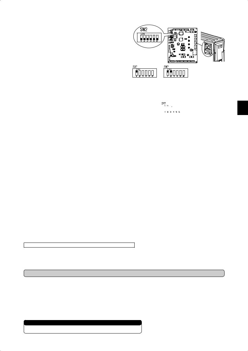
4-4. LOCKING THE OPERATION MODE OF THE AIR CONDITIONER (COOL, DRY, HEAT)
• Description of the function:
With this function, once the operation mode is locked to either COOL/DRY
mode or HEAT mode, the air conditioner operates in that mode only. * Changing the setting is required to activate this function. Please explain about
this function to your customers and ask them whether they want to use it.
[How to lock the operation mode]
1) Be sure to turn off the main power for the air conditioner before making the setting.
2) Set the “1” of SW2 on the outdoor controller board to ON to enable this function.
3) To lock the operation mode in COOL/DRY mode, set the “2” of SW2 on the outdoor controller board to OFF. To lock the operation in HEAT mode, set the same switch to ON.
4) Turn on the main power for the air conditioner.
|
|
|
|
COOL/DRY |
HEAT |
||
4-5. LOWERING THE OPERATION NOISE OF THE OUTDOOR UNIT
• Description of the function:
With this function, the operating noise of the outdoor unit can be lowered by reducing the operation load, for example, during nighttime in COOL mode. However, please note that the cooling and heating capacity may lower if this function is activated.
* Changing the setting is required to activate this function. Please explain about this function to your customers and ask them whether they want to use it.
[How to lower the operating noise] |
|
|
|
|
|
|
|
|
|
|
|
|
|
|
|
1) |
Be sure to turn off the main power for the air conditioner before making the setting. |
|
|
|
|
|
|
|
|
|
|
|
|
|
|
|
|
|
|
|
|
|
|
|
|
|
|
|
|
||
2) |
Set the “3” of SW2 on the outdoor controller board to ON to enable this function. |
|
|
|
|
|
|
|
|
|
|
|
|
|
|
|
|
|
|
|
|
|
|
|
|
|
|
|
|
||
3) |
Turn on the main power for the air conditioner. |
Lower the operating noise |
|||||||||||||
|
|
||||||||||||||
4-6. TEST RUN
•Test runs of the indoor units should be performed individually. See the installation manual coming with the indoor unit, and make sure all the units operate properly.
•If the test run with all the units is performed at once, possible erroneous connections of the refrigerant pipes and the indoor/outdoor unit connecting wires cannot be detected. Thus, be sure to perform the test run one by one.
About the restart protective mechanism
Once the compressor stops, the restart preventive device operates so the compressor will not operate for 3 minutes to protect the air conditioner.
Wiring/piping correction function
This unit has a wiring/piping correction function which corrects wiring and piping combination. When there is possibility of incorrect wiring and piping combination, and confirming the combination is difficult, use this function to detect and correct the combination by following the procedures below.
Make sure that the following is done.
•Power is supplied to the unit.
•Stop valves are open.
Note:
During detection, the operation of the indoor unit is controlled by the outdoor unit. During detection, the indoor unit automatically stops operation. This is not a malfunction.
Procedure
Press the piping/wiring correction switch (SW871) 1 minute or more after turning on the power supply.
•Correction completes in 10 to 15 minutes. When the correction is completed, its result is shown by LED indication. Details are described in the following table.
•To cancel this function during its operation, press the piping/wiring correction switch (SW871) again.
•When the correction completed without error, do not press the piping/wiring correction switch (SW871) again.
When the result was “cannot be corrected”, press the piping/wiring correction switch
(SW871) again to cancel this function. Then, confirm the wiring and piping combination in a conventional manner by operating the indoor units one by one.
•The operation is done while the power is supplied. Make sure not to contact parts other than the switch, including the P.C. board. This may cause electric shock or burn by hot parts and live parts around the switch. Contacting the live parts may cause P.C. board damage.
•To prevent electronic control P.C. board damage, make sure to perform static elimination before operating this function.
•This function does not operate when the outside temperature is 0°C or below.
LED indication during detection:
LED1 |
|
LED2 |
|
|
LED3 |
|
||
(Red) |
|
(Yellow) |
|
|
(Green) |
|
||
Lighted |
|
Lighted |
|
|
Once |
|
||
Result of piping/wiring correction function |
||||||||
|
|
|
|
|
|
|
|
|
LED1 |
|
LED2 |
|
|
LED3 |
|
Result |
|
(Red) |
|
(Yellow) |
|
(Green) |
|
|||
|
|
|
|
|||||
Lighted |
Not lighted |
|
Lighted |
Completed |
||||
|
(Problem corrected or |
|||||||
|
|
|
|
|
|
|
normal) |
|
Once |
|
Once |
|
|
Once |
Not completed |
||
|
|
|
(Detection failed) |
|||||
|
|
|
|
|
|
|
||
|
|
|
|
|
|
|
Refer to “SAFETY PRE- |
|
Other indications |
|
|
CAUTIONS WHEN LED |
|||||
|
|
FLASHES” located behind |
||||||
|
|
|
|
|
|
|
||
|
|
|
|
|
|
|
the service panel. |
|
4-7. EXPLANATION TO THE USER
•Using the OPERATING INSTRUCTIONS, explain to the user how to use the air conditioner (how to use the remote controller, how to remove the air filters, how to remove or put the remote controller in the remote controller holder, how to clean, precautions for operation, etc.).
•Recommend the user to read the OPERATING INSTRUCTIONS carefully.
5. RELOCATION AND MAINTENANCE
5-1. PUMPING DOWN
When relocating or disposing of the air conditioner, pump down the system following the procedure below so that no refrigerant is released into the atmosphere.
1)Connect the gauge manifold valve to the service port of the stop valve on the gas pipe side of the outdoor unit.
2)Fully close the stop valve on the liquid pipe side of the outdoor unit.
3)Close the stop valve on the gas pipe side of the outdoor unit almost completely so that it can be easily closed fully when the pressure gauge shows 0 MPa [Gauge] (0 kgf/cm2).
4)Start the emergency COOL operation on all the indoor units.
To start the emergency operation in COOL mode, disconnect the power supply plug and/or turn off the breaker. After 15 seconds, connect the power supply plug and/or turn on the breaker, and then press the E.O. SW once. (The emergency COOL operation can be performed continuously for up to 30 minutes.)
5)Fully close the stop valve on the gas pipe side of the outdoor unit when the pressure gauge shows 0.05 to 0 MPa [Gauge] (approx. 0.5 to 0 kgf/cm2).
6)Stop the emergency COOL operation.
Press the E.O. SW several times until all LED lamps turn off. Refer to operating instructions for details .
 WARNING
When pumping down the refrigerant, stop the compressor before disconnecting the refrigerant pipes. The compressor may burst if air etc. get into it.
En-
 Loading...