


Equipment Controller (kumo station™)
Model PAC-WHS01HC-E
INSTALLATION MANUAL |
|
FOR INSTALLER |
For safe and correct use, please read this installation manual thoroughly before installing the Equipment Controller.
MANUEL D’INSTALLATION |
|
POUR L’INSTALLATEUR |
|
|
Pour une utilisation correcte et en toute sécurité, veuillez lire attentivement ce manuel d’installation avant d’installer l’Equipment Controller.
MANUAL DE INSTALACIÓN |
|
PARA EL INSTALADOR |
|
|
English
Français
Para un uso seguro y correcto, lea detenidamente este manual de instalación antes de instalar el Equipment |
Español |
|
Controller. |
||
|
Contents |
|
|
1. Safety Instructions..................................................................................................................................................................... |
1 |
|
2. |
Parts.......................................................................................................................................................................................... |
3 |
3. |
System....................................................................................................................................................................................... |
4 |
4. |
Installation................................................................................................................................................................................. |
7 |
5. |
Functions of Switch and LED.................................................................................................................................................. |
11 |
6. |
Wiring and Setting Check........................................................................................................................................................ |
12 |
7. Connected Equipment Information.......................................................................................................................................... |
13 |
|
8. |
Specifications.......................................................................................................................................................................... |
14 |
Mitsubishi Electric is not responsible for the failure of locally supplied parts.
English
1.Safety Instructions
●Before installing the Equipment Controller, make sure you read all the “Safety Instructions.”
●This installation manual contains important safety information. Be sure to comply with the instructions.
●Carefully read the labels attached to the unit.
●After installation, perform the test run to ensure normal operation. Explain to your customer the “Safety Instructions,” use, and maintenance of the unit based on the information in the Installation Manual. The Installation Manual must be given to the user. This manual must always be kept by the actual users.
 Warning
(Improper handling may have serious consequences, including serious injury or death.)
■Users should never install the Equipment Controller on their own.
Improper installation may result in fire, electric shock, or damage/water leaks. Consult the dealer from whom you purchased the unit or professional installer.
■The Equipment Controller must be securely installed on a structure that can sustain its weight.
If the Equipment Controller is mounted on an unstable structure, it may fall down and cause damage or injuries.
■The Equipment Controller must be installed according to the instructions in order to minimize the risk of damage by earthquakes, hurricanes, or strong winds.
Improperly installed Equipment Controller may fall down and cause damage or injuries.
■Connect and fasten the electric wires securely so external force on the wires will not apply on the terminals.
Improper connection and mounting may result in breakdown, heat generation, smoke generation, or fire.
■All electric work must be performed by a qualified technician according to local regulations and the instructions given in this manual.
For the Equipment Controller power line, correct voltage and circuit breakers must be used. Power lines with insufficient capacity or incorrect electrical work may result in electric shock or fire.
■This appliance is not intended for use by persons (including children) with reduced physical, sensory or mental capabilities, or lack of experience and
knowledge, unless they have been given supervision or instruction concerning use of the appliance by a person responsible for their safety.
■The Equipment Controller should be securely installed in accordance with this installation manual.
Improper installation may result in fire, electric shock, or damage.
■Mitsubishi Electric components or other designated components must be used for installation.
Improper component may result in fire, electric shock, or damage/water leaks.
■Cover panel of the Equipment Controller must be firmly affixed.
If the cover panel is mounted improperly, dust and moisture may enter the Equipment Controller, and it may result in fire, electric shock, or damage.
■Do not remodel the Equipment Controller. Consult an installer for repairs.
If alterations or repairs are not performed correctly, it may result in fire, electric shock, or damage.
■The user should never attempt to repair the Equipment Controller or transfer it to another location.
If the Equipment Controller is installed improperly, it may result in fire, electric shock, or damage. If the Equipment Controller needs to be repaired or moved, ask an installer or an authorized technician.
■Do not connect the Equipment Controller to ground inside the indoor unit.
■Do not expose the terminals of sensor and parts.
■The Equipment Controller has signal outputs for equipment (Humidifier, Dehumidifier, Heater etc.); however, it can not isolate power to them in the event of overheating. All equipment connected to the Equipment Controller must comply with National regulation.
■Any heating system connected to Equipment Controller must have it’s own fire protector.
■Only a dealer or qualified technician should install, relocate, reinstall, or repair the device.
■Equipment Controller will automatically manage the operation of the equipment connected to it. Before turning on power to the Equipment Controller, verify that all connected equipment is properly installed and ready for operation.
■Turn off power supply of the equipment when cleaning or performing maintenance work.
EN-1
 Caution
(Improper handling may have consequences, including injury or damage to house.)
■To prevent damage from static electricity, touch a nearby metal body to discharge static electricity from yourself before touching the Equipment Controller.
Static electricity from the human body may damage the Equipment Controller.
■Do not install the Equipment Controller in places with direct sunlight or where the ambient temperature is 104ºF (40ºC) or more or is 32ºF (0ºC) or less.
Direct sunlight and high or low temperature environments may cause the Equipment Controller to deform or breakdown.
■Turn off power supply of Equipment Controller and connected equipment when performing construction or wiring work.
Failure to turn off the power supply to the connected equipment may lead to malfunction or breakdown of the
Equipment Controller or connected equipment.
■Do not install the Equipment Controller where combustible gases may leak, be produced, flow, or accumulate.
If combustible gas accumulates around the Equipment Controller, it may cause fire or explosion.
■When installing the Equipment Controller in a hospital or in a building where communications equipment are installed, you may need to take measures to avoid noise and electronic interference.
Inverters, home appliances, high-frequency medical equipment, and radio communications equipment can cause the Equipment Controller to malfunction or to breakdown. At the same time, the noise and electronic interference from the Equipment Controller may disturb the proper operation of medical equipment, and communications equipment.
■Do not install the Equipment Controller in a place with large amounts of steam, such as bathroom.
Avoid places where water is splashed or where condensation forms on walls. Installing in such places can cause electric shock or breakdown.
■Do not use the Equipment Controller in an unusual environments.
If the Equipment Controller is installed or exposed to steam, volatile oil (including machine oil), corrosive gases, or briny air, the internal parts can be damaged.
■Connect to the indoor unit. (optional)
Please refer to the indoor units “service manual” for detailed instructions for accessing the control interface connector
CN105 on the indoor unit control PCB.
■Do not install the Equipment Controller in outdoor location as it is designed for indoor installation only.
Otherwise, electric shock or breakdown may be caused by water drop, wind, or dust.
■Do not wash the Equipment Controller.
There may be a risk to get an electric shock.
■Before starting operation, check that all protective parts are correctly installed.
Make sure not to get injured by touching high voltage parts.
■Do not touch any switch with wet hands.
There may be a risk to get an electric shock.
Note
■Visit kumocloud.com/resources for additional information about controlling the PAC-WHS01HC-E from your web browser or smart phone.
■The PAC-WHS01HC-E should not be installed and connected to any Mitsubishi Electric system which is to provide cooling or heating to critical applications.
English
EN-2
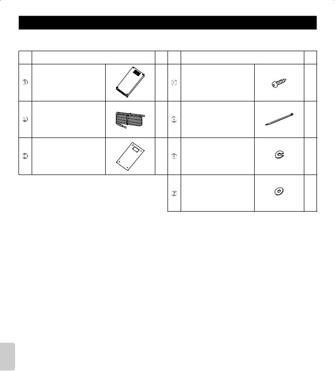
2. Parts
Unit: inch (mm)
The Equipment Controller should be supplied with the following parts.
Parts Name |
Q’ty |
Parts Name |
Q’ty |
|
Equipment Controller |
1 |
Screw for mounting (4×30) |
4 |
|
Indoor unit - Equipment |
1 |
Fastener |
4 |
|
Controller cable 78-3/4” (2000) |
||||
|
|
|
||
Panel for recessed mounting |
1 |
Spring washer |
4 |
|
|
|
Flat washer |
4 |
English
EN-3
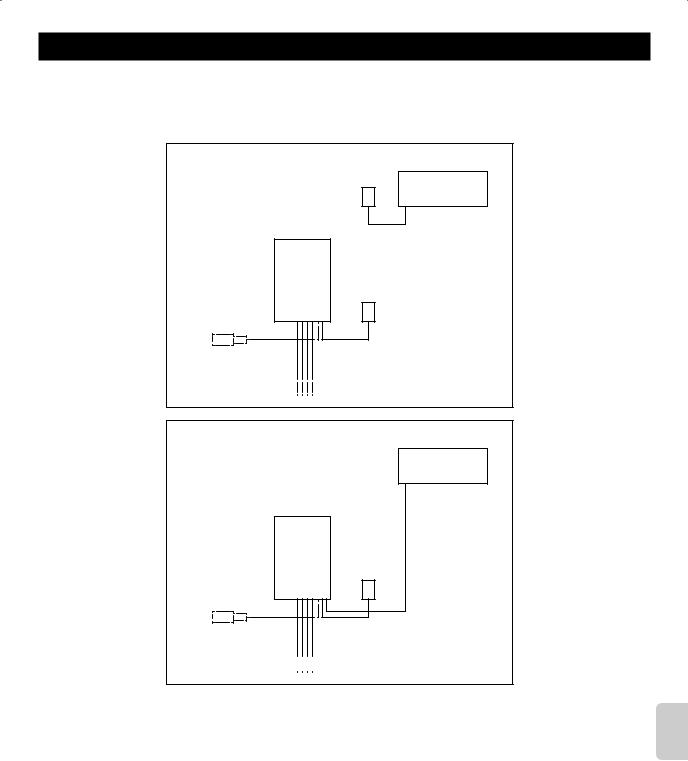
3. System
Please refer to the following information to design your air conditioning system with this Equipment Controller.
3–1. System Outline
This product must be installed while complying with the following restriction: Do not install dehumidifiers inside ducts.
Pattern 1
Wireless
Interface
Indoor unit
Equipment Wireless Outdoor Controller Interface
temperature sensor*
To humidifier, dehumidifier, heater, etc.
Pattern 2
Indoor unit
Equipment Wireless Outdoor Controller Interface
temperature sensor*


 To humidifier, dehumidifier, heater, etc.
*Optional parts
Refer to kumocloud.com/resources for details.
English
EN-4

|
3–2. Wiring Diagram |
|
|
|
|
|
|
|
|
Ch1 |
Ch2 |
Ch3 |
Ch4 |
|
|
|
CN90B |
|
|
|
|
To optional outdoor |
To indoor unit |
|
|
To Wireless Interface |
|
|
temperature sensor |
Connect to CN105 |
|
|
||
|
|
|
(if required) |
|
|
|
|
|
|
CN460 |
|
|
|
|
|
|
(WH) |
|
|
|
|
|
|
|
|
LED7 |
|
|
F1 |
|
|
|
|
|
|
3.15A 250V |
|
|
|
LED2 |
|
|
|
|
|
|
|
|
|
|
|
F2 |
|
|
|
|
|
|
10A 250V |
|
|
|
English |
|
|
|
|
|
8 |
|
|
|
Ch2 |
|
Ch4 |
|
24V |
COM |
Ch1 |
|
|
Ch3 |
|
|
|
|
||||
POWER SUPPLY |
To humidifier, dehumidifier, heater, etc. |
|
24 V AC 60Hz |
||
|
EN-5

3–3. Component Parts
Parts |
Specification |
|
|
|
|
Equipment Controller |
PAC–WHS01HC–E |
|
|
|
|
Wireless Interface |
PAC–USWHS002–WF–1 |
|
|
|
|
Outdoor temperature sensor |
Model: Honeywell C7089U1006 |
|
(Optional parts) |
||
|
||
24 V AC transformer |
Approved certification: UL certification CLASS2 |
|
(LOCALLY SUPPLIED) |
||
|
||
Equipment (Humidifier, Dehumidifier, Heater, etc.) |
24 V AC, MAX. 1 A (each Ch) |
|
(LOCALLY SUPPLIED) |
||
|
English
EN-6
English
4. Installation
4–1. Installation
4–1–1. Choosing the Equipment Controller installation location
●Do not install the Equipment Controller in outdoor location as it is designed for indoor installation only. (The Equipment Controller circuit board and case are not waterproof.)
●Avoid locations where the Equipment Controller is exposed to direct sunlight or other sources of heat.
●Select a location where easy wiring access to the power source is available.
●Avoid locations where combustible gases may leak, be produced, flow, or accumulate.
●Select a level location that can bear the weight of the Equipment Controller.
●Avoid locations where the Equipment Controller is exposed to oil, steam, or corrosive gases.
●Do not install in locations that ambient temperature exceeds 104ºF (40ºC) and relative humidity exceeds 80%.
●Do not install Equipment Controller on top of the indoor unit.
●Depending on the installation, or the type of the wall or post; the accessory screw may not be long enough. In that case, please procure an appropriate screw locally.
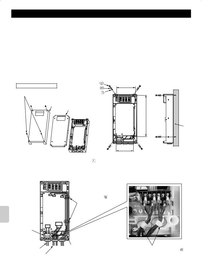
4–1–2. Installing the Equipment Controller |
|
||
Surface mount installation |
Screw |
3-31/32”(100.6) |
|
Spring washer |
|||
Unit: inch (mm) |
|
||
Flat washer |
|
||
Screws |
|
||
|
|
||

 Metal cover
Resin cover
31/32”(253.6)-9
Wall
4-5/32”(105.2) |
1)Remove the 4 screws, and remove the metal cover and the resin cover.
2)Use 4 of the accessory screws for mounting (4x30) to install the Equipment Controller to the wall. Make sure to use
each screw with 1 spring washer and 1 flat washer
 .
.
3) Connect the equipment lead wires to the controller board. (Refer to “4-2. Wiring”.)
4) Use the fasteners  to bind the connected lead wires. Pass the fasteners
 through the cut-out holes on the resin case and secure the lead wires. Use the mounting cord clamp to affix the power supply cable.
Affix the power supply cable with the mounting cord clamp.
Power supply cables
Lead wire for equipment connection
Pass the fasteners through the holes on the resin case to affix the lead wires.
Lead wire for the outdoor temperature sensor Lead wire for indoor unit connection
Lead wire for the Wireless Interface connection
The maximum number of cables to be affixed with 1 fastener
is 4. If more than 4 cables are to be affixed, use 2 fasteners  .
.
5) Attach the resin cover, and affix the metal cover with the 4 screws.
EN-7

Recessed mount installation
Unit: inch (mm)
6-11/16“ (170)
13/32“ (10)
3/16“ (5)
12-25/32“ (325)
1)Cut out the wall using the dimensions in the left figure.
2)Remove the 4 screws, and remove the metal cover and the resin cover. Note: This procedure is the same as the wall surface mount installation.
3)Connect the equipment lead wires to the controller board. (Refer to “4-2.
Wiring”)
4)Use the accessory fasteners to affix the connected lead wires. Use the mounting cord clamp to affix the power supply cable.
Note: Refer to the figure in the procedure of the wall surface mount installation for the routing layout of the lead wires.
5)Use the 3 screws to install the Equipment Controller to the post. Make sure
to use each screws with 1 spring washer
 and 1 flat washer
 . Notes:
●Do not damage the controller board’s lead wires when affixing the screws.
●When installing on a post, the level difference between the wall surface and the Equipment Controller’s cover must be 1/32” (1) or less.
6)Attach the resin cover, and affix the panel for recessed mounting  with the 4 screws.
post |
|
|
|
|
|
|
|
|
|
|
|
|
|
|
|
|
|
|
|
|
|
|
|
Screw(4×30) , Spring washer , Flat washer |
|||||
|
|
|
|
|
|
|
|
|
|
|
|
|
|
|
|
|
|
|
|
|
|
|
|||||||
|
|
|
|
|
|
|
|
|
|
|
|
|
|
|
|
|
|
|
|
|
|
|
|||||||
|
|
|
|
|
|
|
|
|
|
|
|
|
|
|
|
|
|
|
|
|
|
|
|||||||
|
|
|
|
|
|
|
|
|
|
|
|
|
|
|
|
|
|
|
|
|
|
|
|||||||
|
|
|
|
|
|
|
|
|
|
|
|
|
|
|
|
|
|
|
|
|
|||||||||
|
|
|
|
|
|
|
|
|
|
|
|
|
|
|
Wall |
||||||||||||||
|
|
|
|
|
|
|
|
|
|
|
|
|
|
|
|
||||||||||||||
|
Screw (4×30) |
|
|
|
|||||||||||||||||||||||||
|
|
||||||||||||||||||||||||||||
|
|
|
|
|
|
|
|
|
|
|
|
|
|
|
|
|
|
|
|
|
|
|
|
|
|
|
|
|
|
difference:Level |
0±1/32“(1) |
post |
|
Resin cover |
Panel for recessed |
Screw: 4 pieces |
|
mounting |
||
|
||
|
|
English
EN-8
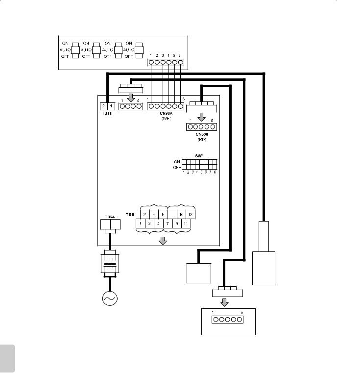
4–2. Wiring |
|
|
|
|
4–2–1. Wiring method |
|
|
|
|
*Optional parts |
|
|
|
CN90B |
|
|
|
|
|
|
|
|
|
(WH) |
Ch1 |
Ch2 |
Ch3 |
Ch4 |
|
|
|
|
CN460 |
|
|
|
|
(WH) |
|
|
|
|
Ch2 |
Ch4 |
|
|
|
|
8 |
|
|
24V COM |
|
|
|
|
|
Ch1 |
Ch3 |
|
|
|
Connect to equipment |
|
|
|
|
Note: Connect surge absorber |
|
24 V AC |
|
|
according to the load at site. |
|
|
|
|
|
|
Transformer |
|
|
Wireless |
|
|
|
|
|
|
|
|
|
|
Interface |
|
|
|
|
Outdoor |
|
|
|
|
temperature |
|
|
|
|
sensor* |
|
|
|
|
CN105 |
Wiring specification |
|
|
|
Indoor unit |
|
|
|
|
|
English |
Power cable |
AWG 18–22 |
|
|
|
||
Equipment cable |
Connect by caulking a round terminal |
||
|
|||
|
|
|
|
|
Outdoor temperature sensor cable |
AWG 16–22 (Note: AWG 18 is recommended) |
|
|
|
|
 Warning
All electrical work should be carried out by a suitably qualified technician. Failure to comply with this could result in electrocution, fire, and death. All wiring must be conducted according to the national wiring regulations.
Notes:
●Disconnect power supply before connecting wires.
●Do not route wires near equipment generating noise.
●Do not bundle power cables and equipment cables together with other cables.
●Indoor unit-Equipment Controller cable, Wireless Interface cable, and sensor cables should be segregated from each other until entry into the Equipment Controller. Also avoid running cables along metal surfaces.
●Use copper supply wires.
EN-9
<Power supply>
Use an insulated transformer equivalent to CLASS2 UL Standard for the power supply of the Equipment Controller, and connect input 24 V AC to TB24.
Select an appropriate transformer based on the equipment to be connected to TBE.
Electrical ratings
Terminal |
Voltage |
Running Current |
TB24 1-2 |
20–30 V AC |
MAX. 0.4 A (Excluding the current of equipment connected to the TBE) |
<Connecting to Indoor unit>
Use the accessory cable for connecting CN460 on the Equipment Controller to CN105 on the indoor controller board.
<Connecting Wireless Interface>
When connecting Wireless Interface, connect it to CN506 on the Equipment Controller.
Regarding the initial setting of Wireless Interface, refer to the Wireless Interface Installation Manual.
<Connecting Outdoor Temperature Sensor>
Connect the sensor cable to the TBTH on the Equipment Controller. Use only C7089U1006 Outdoor Temperature Sensor (Honeywell).
Wire length between C7089U1006 and Equipment Controller must be less than 200 feet. For more information regarding the installation, refer to the C7089U1006 Installation Manual.
<Connecting to Equipment>
A maximum of 4 Equipment can be connected to the Equipment Controller. Ch3 and Ch4 can be switched between wet and dry contacts.
Electrical ratings
Terminal |
Description |
Voltage |
Current |
|
|
|
|
7-9 |
Wet contact only |
20–30 V AC |
0.01–1 A |
|
|
|
|
8-0 |
Wet contact only |
20–30 V AC |
0.01–1 A |
1-5 |
Dry contact only* |
20–30 V AC |
0.01–1 A |
2-6 |
Dry contact only* |
20–30 V AC |
0.01–1 A |
7-1 |
Dry contact only* |
20–30 V AC |
0.01–1 A |
|
|
|
|
8-2 |
Dry contact only* |
20–30 V AC |
0.01–1 A |
|
|
|
|
*Each terminal should be provided by a UL certification CLASS2 or equivalent power supply.
Notes:
●Connect the terminals by using the ring terminals when wiring to TBE.
●Connect the surge absorber according to the load at site.
 Warning
Any heating system connected to Equipment Controller must have its own fire protector.
Terminal board screw tightening torque
|
Tightening torque (ft·lbs) |
TB24 |
0.89-1.03 |
TBE |
0.37-0.44 |
TBTH |
0.37-0.44 |
Connecting NON-POWERED Equipment
Ch3 |
Ch4 |
|
|
|
|
|
|
|
|
|
|
|
|
|
|
|
|
|
|
|
|
|
|
|
|
|
|
|
|
|
|
|
|
|
|
|
|
|
|
|
|
|
|
|
|
|
|
|
|
|
|
|
|
|
|
|
|
|
|
|
|
NON-POWERED |
|
NON-POWERED |
||||||||||||
Equipment |
|
Equipment |
||||||||||||
|
|
|
|
|
|
|
|
|
|
|
|
|
|
|
Connecting POWERED Equipment
Ch1* Ch2* Ch3* Ch4*
|
|
|
|
|
|
|
|
|
|
|
|
|
|
|
|
|
|
|
|
|
|
|
|
|
|
|
|
|
|
|
|
|
|
|
|
|
|
|
|
|
|
|
|
|
|
|
|
|
|
|
|
|
|
|
|
|
|
|
|
|
|
|
|
|
|
|
|
|
|
|
|
|
|
|
|
|
|
|
|
|
|
|
|
|
|
|
|
|
|
|
|
|
|
|
|
|
|
|
|
|
|
|
|
|
|
|
|
|
|
|
|
|
|
|
|
|
|
|
|
|
|
|
|
|
|
|
|
|
|
|
|
|
|
|
|
|
POWERED |
|
|
|
POWERED |
|
|
POWERED |
|
|
|
POWERED |
|||||||||||||||||||||
|
Equipment |
|
|
|
Equipment |
|
|
Equipment |
|
|
|
Equipment |
|||||||||||||||||||||
|
|
|
|
|
|
|
|
|
|
|
|
|
|
|
|
|
|
|
|
|
|
|
|
|
|
|
|
|
|
|
|
|
|
24 V AC |
|
|
|
|
|
|
24 V AC |
|
|
|
|
|
|
24 V AC |
|
|
|
|
|
24 V AC |
|
|
|
|
|
|
|||||||
|
|
|
|
|
|
|
|
|
|
|
|
|
|
|
|
|
|
|
|
|
|
|
|||||||||||
|
|
|
|
|
|
|
|
|
|
|
|
|
|
|
|
|
|
|
|
|
|
|
|||||||||||
|
|
|
|
|
|
|
|
|
|
|
|
|
|
|
|
|
|
|
|
|
|||||||||||||
Transformer |
|
|
|
|
|
Transformer |
|
|
|
|
|
Transformer |
|
|
|
|
Transformer |
|
|
|
|
|
|||||||||||
|
|
|
|
|
|
|
|
|
|
|
|
|
|
|
|
|
|
|
|
|
|
|
|
|
|
|
|
|
|
|
|
|
|
|
|
|
|
|
|
|
|
|
|
|
|
|
|
|
|
|
|
|
|
|
|
|
|
|
|
|
|
|
|
|
|
|
|
4–2–2. How to set the Function Setting Switch (SW1)
The Function Setting Switch |
|
|
|
|
SW1 |
|
|
|
||
(SW1) must properly be set |
ON |
|
|
|
|
|
|
|
|
|
according to the usage of the |
OFF |
|
|
|
|
|
|
|
|
|
1 |
2 |
3 |
4 |
5 |
6 |
7 |
8 |
|||
|
||||||||||
Equipment Controller.
For the details, refer to “5.1.
Function Setting Switch (SW1)”.
English
EN-10

English
5. Functions of Switch and LED
5–1. Function Setting Switch (SW1)
1)Turn OFF the power supply of the product before switching the Function Setting Switch.
2)Set the Function Setting Switch (SW1) properly according to the Equipment Controller’s usage.
●Set SW1–1 to 1–4 to change the initial state of relay contact for safety.
Equipment Controller will reset if it doesn’t communicate to Wireless Interface for several minutes. After that, relay contact state will become state indicated by these SW1–1 to 1–4.
Recommended settings vary depending on the equipment connected to each Ch.
Refer to kumocloud.com/resources for details.
●Set SW1–6 and 1–7 to ON or OFF according to the power supply status to the connecting equipment of Ch3 and 4.
●Set SW1–5 to ON when the Equipment Controller is not connected to an indoor unit.
SW No |
Function |
ON |
OFF |
SW 1–1 |
Switching initial close/open of Ch1 contact |
Ch1: Contact is close |
Ch1: Contact is open |
|
|
|
|
SW 1–2 |
Switching initial close/open of Ch2 contact |
Ch2: Contact is close |
Ch2: Contact is open |
|
|
|
|
SW 1–3 |
Switching initial close/open of Ch3 contact |
Ch3: Contact is close |
Ch3: Contact is open |
|
|
|
|
SW 1–4 |
Switching initial close/open of Ch4 contact |
Ch4: Contact is close |
Ch4: Contact is open |
|
|
|
|
SW 1–5 |
Switching the connection status of indoor units |
Without indoor unit connection |
With indoor unit connection |
|
|
|
|
SW 1–6 |
Switching wet contact/dry contact of Ch3 |
Ch3: Wet contact |
Ch3: Dry contact |
|
|
|
|
SW 1–7 |
Switching wet contact/dry contact of Ch4 |
Ch4: Wet contact |
Ch4: Dry contact |
|
|
|
|
SW 1–8 |
|
not use |
|
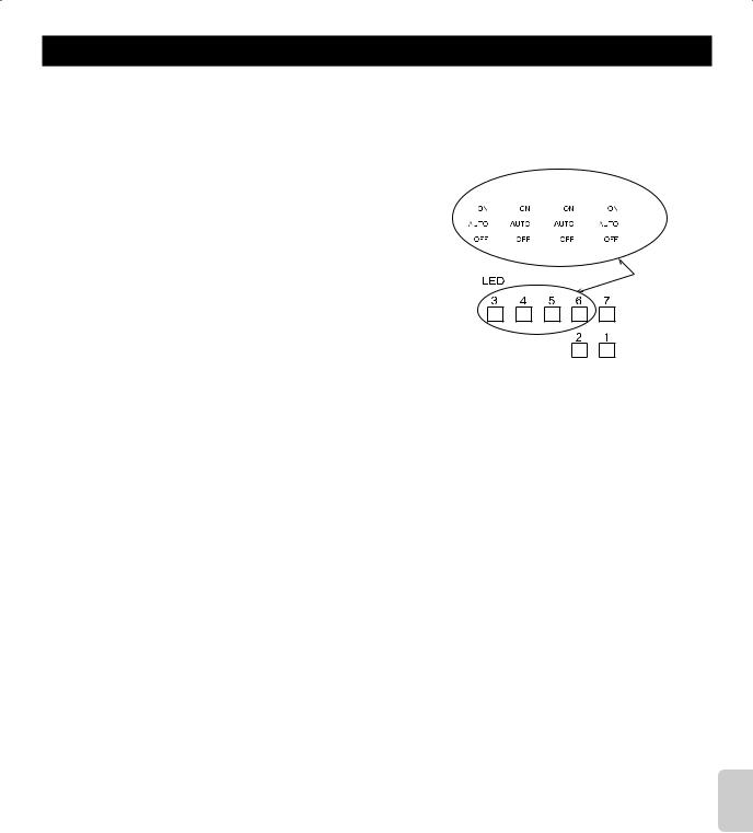
5–2. Emergency Operation Switches (Ch1, 2, 3, 4) |
|
|
|
|
|
|
|
|
|
|
|
|
|
|
|
|
|
||||||
The Emergency Operation Switches provide an ability to override the output status |
|
|
|
|
|
|
|
|
|
|
|
|
|
||||||||||
of the 4 Equipment Controller outputs which control connected equipment. |
|
|
|
|
|
|
|
|
|
|
|
|
|
|
|
||||||||
|
|
|
|
|
|
|
|
|
|
|
|
|
|
|
|||||||||
To operate the equipment from kumo cloud™, set switch state to “Auto”. |
|
|
|
|
|
|
|
|
|
|
|
|
|
|
|
||||||||
|
|
|
|
|
|
|
|
|
|
|
|
|
|
|
|||||||||
|
|
|
|
|
|
|
|
|
|
|
|
|
|
|
|
|
|
|
|
|
|
|
|
|
Switch state |
|
Function |
|
|
|
|
|
|
|
|
|
|
|
|
|
|
|
|
|
|||
|
|
|
|
|
|
Ch1 Ch2 Ch3 Ch4 |
|
|
|||||||||||||||
|
ON |
|
Closes Ch1, 2, 3, 4 contact and permits equipment operation. |
|
|
|
|||||||||||||||||
|
|
|
|
|
|
|
|
|
|
|
|
|
|
|
|
||||||||
|
|
|
|
|
|
|
|
|
|
|
|
|
|
|
|
|
|
|
|||||
|
AUTO |
|
Remotely sets an open/close status of Ch1, 2, 3, 4 contact. |
|
|
|
|
|
|
|
|
|
|
|
|
|
|
|
|||||
|
|
|
|
|
|
|
|
|
|
|
|
Emergency |
|
||||||||||
|
OFF |
|
Opens Ch1, 2, 3, 4 contact and prohibits equipment operation. |
|
|
|
|
|
|
|
|
|
|||||||||||
|
|
|
|
|
|
|
|
|
|
|
|
|
|
|
|
|
Operation |
||||||
Note: If changing the setting of the Emergency Operation Switches of the Equipment Controller |
|||||||||||||||||||||||
|
|
|
|
Switches |
|||||||||||||||||||
|
does not change the relay contact output, please contact your contractor for service. |
|
|
|
|
||||||||||||||||||
|
|
|
|
|
|
|
|
|
|
|
|||||||||||||
5–3. LED Function |
|
|
|
|
LED1 to 6 : Green |
|
LED7 : Orange |
||||||||||||||||
|
|
|
|
|
|
|
|
: ON |
: OFF |
|
: Blinking |
- : N/A |
|||||||||||
No |
|
Description |
LED1 |
LED2 |
LED3 |
|
LED4 |
LED5 |
|
LED6 |
|
|
LED7 |
||||||||||
1 |
Starting up for 3 seconds |
(0.5–sec |
(0.5–sec |
(0.5–sec |
|
(0.5–sec |
(0.5–sec |
|
(0.5–sec |
|
|
(0.5–sec |
|||||||||||
|
|
|
|
interval) |
interval) |
interval) |
|
interval) |
interval) |
|
interval) |
|
|
interval) |
|||||||||
2 |
Equipment connected to Ch1 is |
- |
- |
|
|
- |
|
- |
|
|
- |
|
|
|
|
- |
|
||||||
permitted to operate (Contact: Close) |
|
|
|
|
|
|
|
|
|
|
|||||||||||||
3 |
Equipment connected to Ch2 is |
- |
- |
- |
|
|
|
- |
|
|
- |
|
|
|
|
- |
|
||||||
permitted to operate (Contact: Close) |
|
|
|
|
|
|
|
|
|
|
|||||||||||||
4 |
Equipment connected to Ch3 is |
- |
- |
- |
|
- |
|
|
|
|
- |
|
|
|
|
- |
|
||||||
permitted to operate (Contact: Close) |
|
|
|
|
|
|
|
|
|
|
|||||||||||||
5 |
Equipment connected to Ch4 is |
- |
- |
- |
|
- |
|
- |
|
|
|
|
|
|
|
|
|
|
- |
|
|||
permitted to operate (Contact: Close) |
|
|
|
|
|
|
|
|
|
|
|
|
|
||||||||||
6 |
Outdoor temperature sensor: Normal |
- |
|
- |
|
- |
|
- |
|
|
- |
|
|
|
|
- |
|
||||||
|
|
|
|
|
|
|
|
|
|
|
|
|
|
|
|
|
|
|
|
|
|
||
7 |
Outdoor temperature sensor: Fault |
- |
(0.5–sec |
- |
|
- |
|
- |
|
|
- |
|
|
|
|
(0.5–sec |
|||||||
|
|
|
|
|
interval) |
|
|
|
|
|
|
|
|
|
|
|
|
|
|
|
interval) |
||
8 |
Outdoor temperature sensor: Not |
- |
|
- |
|
- |
|
- |
|
|
- |
|
|
|
|
- |
|
||||||
connected |
|
|
|
|
|
|
|
|
|
|
|
|
|||||||||||
9 |
Initiating communication with the indoor |
|
- |
- |
|
- |
|
- |
|
|
- |
|
|
|
|
- |
|
||||||
unit |
|
|
|
|
|
|
|
|
|
|
|
|
|||||||||||
10 |
Communicating with the Wireless |
(0.1–sec |
- |
- |
|
- |
|
- |
|
|
- |
|
|
|
|
- |
|
||||||
Interface or indoor unit |
|
|
|
|
|
|
|
|
|
||||||||||||||
|
|
|
|
blinking) |
|
|
|
|
|
|
|
|
|
|
|
|
|
|
|
|
|
|
|
EN-11
6. Wiring and Setting Check
Before turning ON the power, ensure that following equipment is properly installed according to the manuals: Wireless
Interface, Equipment Controller, indoor unit, and outdoor unit.
After that, turn ON the power of the Equipment Controller and the indoor units.
1)Emergency Operation Check
Check if SW1–6 and 1–7 are properly set according to “4-2-2. How
to set the Function Setting Switch (SW1)”. |
Ch1 Ch2 |
Ch3 |
Ch4 |
||||||||
Firstly, set Ch1 to 4 of the Emergency Operation Switches to ON. |
|
|
|
|
|
|
|
|
|
|
|
|
|
|
|
|
|
|
|
|
|
|
|
● Check if LED3 to 6 of the Equipment Controller lights. |
|
|
|
|
|
|
|
|
|
|
|
● Check if the equipment connected to the TBE operates properly. |
|
|
|
|
|
|
|
|
|
|
Please Check |
|
|
|
|
|
|
|
|
|
|
||
Secondly, set Ch1 to 4 of the Emergency Operation Switches to |
|
|
|
|
|
|
|
|
|
|
|
OFF. |
|
|
|
|
|
|
|
|
|
|
|
●Check if LED3 to 6 of the Equipment Controller are OFF.
●Check if the operation of the equipment connected to the TBE
stopped.
2)Function Setting Switch Check
Check if SW1–1 to 1–4 are properly set.
(1) Turn OFF the power of the Equipment Controller. (2) Set the Emergency Operation Switches to AUTO.
(3) Disconnect the connector CN506 for Wireless Interface. (4) Turn ON the power of the Equipment Controller.
After turning ON the power, ensure that the LED3 to 6, which correspond to the Ch set to ON using SW1–1 to 1–4, lights. In the same way, ensure that the LED3 to 6, which correspond to the Ch set to OFF using SW1–1 to 1–4, extinguishes.
For the correspondence of SW1 with each Ch, refer to “5–1. Function Setting Switch (SW1)”; and for the correspondence of each Ch with LED, refer to “5–3. LED Function”.
3)Communication Check
Check if LED1 of the Equipment Controller blinks when both of the following conditions are met:
●When 5 minutes have passed since turning ON the power of the
Equipment Controller and the indoor unit.
●When the setting of Wireless Interface has been completed.
4)Operation Check of Outdoor Temperature Sensor
When the outdoor temperature sensor is in use, check if the LED2 of the Equipment Controller lights up after turning ON the power.
English
EN-12
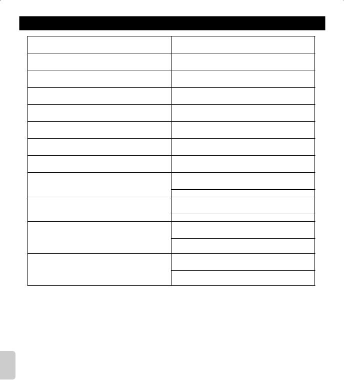
7. Connected Equipment Information
Wireless Interface address (MAC)
Wireless Interface serial number (ID)
Indoor unit model name
Indoor unit serial number
Outdoor unit model name
Outdoor unit serial number
System commissioning date
Equipment Controller installation date
Model name of the equipment connected to Ch1
initial contact state close/open
Model name of the equipment connected to Ch2
initial contact state close/open
Model name of the equipment connected to Ch3
initial contact state close/open wet contact/dry contact
Model name of the equipment connected to Ch4
initial contact state close/open wet contact/dry contact
English
EN-13
 Loading...