


PAR-U02MEDA
CITY MULTI Control System
Smart ME Controller PAR-U02MEDA
Installation Manual
Prior to use, thoroughly read the instructions in this manual to use the product correctly.
Retain this manual for future reference.
Make sure that the CD-ROM, this manual, and Simple Operation Manual are passed on to
any future users.
To ensure safety and proper operation of the remote controller, the remote controller should
only be installed by qualified personnel.
For distribution to dealers and contractors
English
– 1 –
Chapter 1. Installation
This installation manual describes how to install the Smart ME Controller for use with Mitsubishi
Building Air Conditioning System, direct expansion type CITY MULTI air conditioner indoor units (“-A”
type and later).
Please be sure to read this installation manual and Instruction Book that are supplied with the Remote
Controller before proceeding with the installation. Failure to follow the instructions may result in
equipment damage.
For information on how to wire and install the air conditioning units, refer to the Air Conditioner
Installation Manual.
After the installation, hand over this manual to users.
Smart ME Controller is a type of ME Remote Controllers, sometimes simply referred to as ME Remote
Controller.
• Read the following safety precautions prior to installation.
• Observe these precautions carefully to ensure safety.
• After reading this manual, pass it on to the end user to retain for future reference.
• Keep this manual for future reference and refer to it as necessary. This manual should be made
available to those who repair or relocate the controller. Make sure that the manual is passed on to
any future users.
WARNING
1 Safety Precautions
WARNING
Indicates a risk of death or serious injury.
CAUTION
Indicates a risk of serious injury or structural damage.
General precautions
All electric work must be performed by qualified personnel.
Do not install the unit in a place where large amounts of
oil, steam, organic solvents, or corrosive gases, such
as sulfuric gas, are present or where acidic/alkaline
solutions or sprays are used frequently. These
substances can compromise the performance of the
unit or cause certain components of the unit to corrode,
which can result in electric shock, malfunctions,
smoke, or fire.
To reduce the risk of shorting, current leakage, electric
shock, malfunctions, smoke, or fire, do not wash the
controller with water or any other liquid.
To reduce the risk of electric shock, malfunctions,
smoke or fire, do not operate the switches or touch
other electrical parts with wet hands.
To reduce the risk of injury or electric shock, before
spraying a chemical around the controller, stop the
operation and cover the controller.
To reduce the risk of injury or electric shock, stop the
operation and switch off the power supply before
cleaning, maintaining, or inspecting the controller.
Properly install all required covers to keep moisture
and dust out of the controller. Dust accumulation and
water can cause electric shock, smoke, or fire.
To reduce the risk of injury, keep children away while
installing, inspecting, or repairing the controller.
– 2 –
CAUTION
WARNING
CAUTION
WARNING
CAUTION
Precautions during installation
Precautions during wiring
To reduce the risk of fire or explosion, do not place
flammable materials or use flammable sprays around
the controller.
To reduce the risk of damage to the controller, do not
directly spray insecticide or other flammable sprays on
the controller.
To reduce the risk of electric shock or malfunctions, do
not touch the touch panel with a pointy or sharp object.
To reduce the risk of injury and electric shock, avoid
contact with sharp edges of certain parts.
To avoid injury from broken glass, do not apply
excessive force on the glass parts.
To reduce the risk of injury, wear protective gear when
working on the controller.
Do not directly stare at the LED light, as this may
damage your eyes.
Do not install the controller where there is a risk of
leaking flammable gas. If flammable gas accumulates
around the controller, it may ignite and cause a fire or
explosion.
Properly dispose of the packing materials. Plastic bags
pose suffocation hazard to children.
Take appropriate safety measures against earthquakes
to prevent the controller from causing injury.
To prevent injury, install the controller on a flat surface
strong enough to support its weight.
To reduce the risk of shorting, current leakage, electric
shock, malfunctions, smoke, or fire, do not install the
controller in a place exposed to water or in a
condensing environment.
Controller must be installed by qualified personnel
according to the instructions detailed in the Installation
Manual.
Improper installation may result in electric shock or fire.
When attaching the cover and the top casing to the
bottom casing, push it until it they click into place. If
they are not properly locked into place, they may fall,
causing personal injury, controller damage, or
malfunctions.
To reduce the risk of damage to the controller,
malfunctions, smoke, or fire, do not connect the power
cable to the signal terminal block.
Properly secure the cables in place and provide
adequate slack in the cables so as not to stress the
terminals. Improperly connected cables may break,
overheat, and cause smoke or fire.
To reduce the risk of injury or electric shock, switch off
the main power before performing electrical work.
All electric work must be performed by a qualified
electrician according to the local regulations,
standards, and the instructions detailed in the
Installation Manual. Capacity shortage to the power
supply circuit or improper installation may result in
malfunction, electric shock, smoke, or fire.
To reduce the risk of current leakage, overheating,
smoke, or fire, use properly rated cables with adequate
current carrying capacity.
To reduce the risk of electric shock, shorting, or
malfunctions, keep wire pieces and sheath shavings
out of the terminal block.
To reduce the risk of shorting, current leakage, electric
shock, or malfunctions, keep the cables out of contact
with controller edges.
To reduce the risk of electric shock, malfunctions, or
fire, seal the gap between the cables and cable access
holes with putty.

– 3 –
WARNING
CAUTION
The CD-ROM that is supplied with Smart ME Controller
The CD-ROM that is supplied with the Smart ME Controller contains an Installation Manual and
Instruction Book.
Each document is in PDF format.
Viewing documents requires a computer with Adobe
®
Reader
®
or Adobe
®
Acrobat
®
installed.
Precautions for moving or repairing the controller
Additional precautions
WARNING
The CD-ROM can only be played on a CD-drive or a DVD-drive. Do not attempt to play the
CD-ROM on an audio CD player as this may damage your ears and/or speakers.
“Adobe
®
Reader
®
” and “Adobe
®
Acrobat
®
” are registered trademarks of Adobe Systems Incorporated.
The controller should be repaired or moved only by
qualified personnel.
Do not disassemble or modify the controller.
Improper installation or repair may cause injury, electric
shock, or fire.
To reduce the risk of shorting, electric shock, fire, or
malfunction, do not touch the circuit board with tools or
with your hands, and do not allow dust to accumulate
on the circuit board.
To avoid damage to the controller, use appropriate
tools to install, inspect, or repair the controller.
This controller is designed for exclusive use with the
Building Management System by Mitsubishi Electric.
The use of this controller for with other systems or for
other purposes may cause malfunctions.
Take appropriate measures against electrical noise
interference when installing the air conditioners in
hospitals or facilities with radio communication
capabilities. Inverter, high-frequency medical, or
wireless communication equipment as well as power
generators may cause the air conditioning system to
malfunction. Air conditioning system may also
adversely affect the operation of these types of
equipment by creating electrical noise.
To avoid malfunctions, do not bundle power cables and
signal cables together, or place them in the same
metallic conduit.
To prevent malfunctions, do not remove the protective
film or the circuit board from the casing.
To avoid damage to the controller, do not overtighten
the screws.
Use a flat-head screwdriver with a blade width of 4-5.5 mm
(5/32-7/32 in). The use of a screwdriver with a narrower or
wider blade tip may damage the controller casing.
To prevent damage to the controller casing, do not
force the driver to turn with its tip inserted in the slot.
To avoid discoloration, do not use benzene, thinner, or
chemical rag to clean the controller. To clean the
controller, wipe with a soft cloth soaked in water with
mild detergent, wipe off the detergent with a wet cloth,
and wipe off water with a dry cloth.
To avoid damage to the controller, provide protection
against static electricity.
Do not use solderless terminals to connect cables to
the terminal block.
Solderless terminals may come in contact with the
circuit board and cause malfunctions or damage the
controller cover.
To avoid damage to the controller, do not make holes
on the controller cover.
To avoid deformation and malfunction, do not install
the remote controller in direct sunlight or where the
ambient temperature may exceed 40ºC (104ºF) or
drop below 0ºC (32ºF).
Do not install the controller on the control panel door.
Vibrations or shocks to the controller may damage the
controller or cause the controller to fall.
Hold the cables in place with clamps to prevent undue
force from being applied to the terminal block and
causing cable breakage.
To prevent cable breakage and malfunctions, do not
hang the top controller casing hang by the cable.
– 4 –
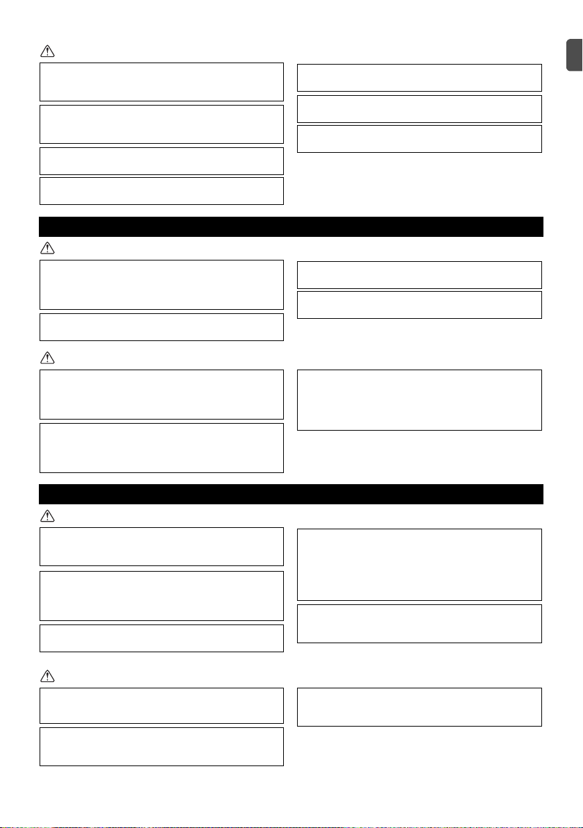
The following parts are included in the box.
(1) Field-supplied parts
(2) Required tools
• Flat-tip screwdriver (Width: 4-5.5 mm (5/32-7/32 in))
• Knife or nipper
• Miscellaneous tools
2 Component names and supplied parts
*1 The front cover is already installed on the top case at
factory shipment.
*2 ISO metric screw thread
*3 Remote controller cable is not included.
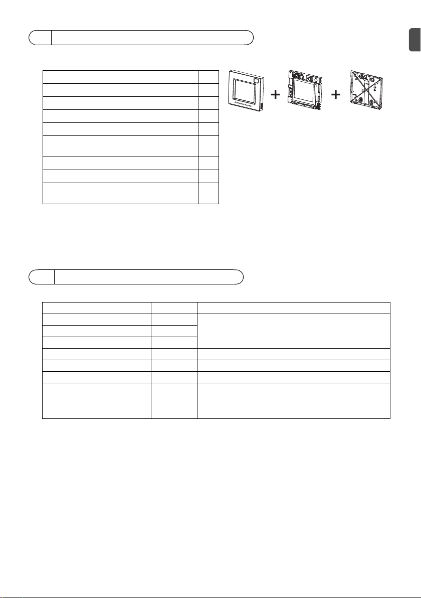
3 Field-supplied parts/Required tools
Parts name Qty. Notes
Double switch box 1
Not required for direct wall installationThin metal conduit As needed
Locknut and bushing As needed
Cable cover As needed Required for routing remote controller cable along a wall
Putty As needed
Molly anchor As needed
Remote controller cable
(0.3 mm² (AWG 22) 2-core
sheathed cable)
As needed
If the remote controller cable exceeds 10 m (32 ft), use an
electric wire that meets the following specification.
CVVS: 1.25 mm
2
(standard AWG 16) or equivalent
CPEVS: ø1.2 mm (standard AWG 16) or equivalent
Parts name Qty.
Remote controller (front cover) *1 1
Remote controller (top case) *1 1
Remote controller (bottom case) 1
Roundhead cross slot screws M4×30 *2 4
Wood screw 4.1×16 *2
(for direct wall installation)
4
Installation Manual (this manual) 1
Simple Operation Manual 1
CD-ROM
(Installation Manual, Instruction Book)
1
Bottom case
Front cover
Top case
– 5 –
*1 The power consumption coefticient of the Smart ME Controller is “0.5” and that of a ME Remote Controller
(PAR-F27MEA) is “0.25”.
If the number of Smart ME Controllers is high and the total power supply they require exceeds the outdoor unit's
ability to supply power, a Transmission booster (PAC-SF46EPA) will be required.
*1: "7" for the P200 and P250 models
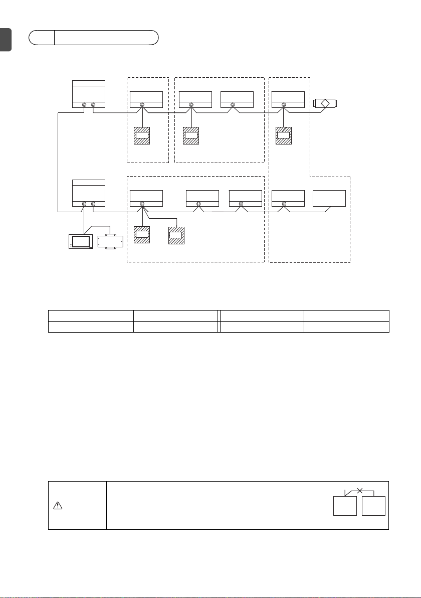
(1) Wiring from the remote controller
• Connect to TB5 (terminal block for indoor-outdoor transmission cable) on any indoor unit in same
M-NET system.
• The terminal block has no polarity. Connect to the terminals M1 and M2.
(2) Operating in a group (Groups 01, 02, 03, and 04)
• Assign the lowest address to the main indoor unit in the group.
The remote controller address should be set to a number that equals the main indoor unit address
plus 100.
(3) Up to two remote controllers (main and sub) can be connected to an indoor unit or a group of
indoor units.
• Connect the main and sub remote controllers in the same way as described in (1) above.
• Be sure to set the main and sub remote controller addresses.
The sub remote controller address should be set to a number that equals the main indoor unit
address plus 150.
4 System diagram
Outdoor unit Transmission booster Indoor unit Smart ME Controller
32 25 1
(*1)
0.5
CAUTION
- Remote controllers cannot be wired together. Only one
cable can be connected to the remote controller terminal
block.
- The ME remote controller and MA remote controller
cannot be connected in the same group.
051
TB7 TB3 TB5
001
TB5
002
TB5
003
TB5
004
101 102 104
056
TB7 TB3 TB5
009
TB5
008
TB5
007
TB5
006
107
157
CENTRALIZED CONTROLLER AG-150A
201
000
Outdoor unit
Smart ME
Controller *1
Indoor unit
Indoor unit
Smart ME
Controller
Indoor unit
Indoor unit
Smart ME
Controller
Indoor unit
Smart ME
Controller
Smart ME
Controller
Indoor unit
Indoor unit
Indoor unit
Outdoor unit
Centralized
controller
Power supply
unit
LOSSNAY unit
005
Advanced HVAC
CONTROLLER (AHC)
Group 01
Group 02
Group 03
Group 04
Main
remote
controller
Sub
remote
controller
– 6 –
This remote controller is for the wall installation. It can be installed either in the switch box or directly
on the wall. When performing direct wall installation, cables can be thread through either back or top
of the remote controller.
(1) Selecting an installation site
Install the remote controller (switch box) on the site where the following conditions are met.
(a) A flat surface
(b) A place where the remote controller can measure the accurate room temperature and humidity
Sensors to monitor the room temperature are on the indoor unit and on the remote controller.
When the room temperature is monitored with the sensor on the remote controller, the main
remote controller monitors the room temperature. When using the sensor on the remote controller,
follow the instructions below.
• To monitor the accurate room temperature and humidity, install the remote controller away from
direct sunlight, heat sources, and the supply air outlet of the air conditioner.
• Install the remote controller in a location that allows the sensor to measure the representative
room temperature and humidity.
• Install the remote controller where no wires are routed around the temperature sensor on the
controller or where no obstacles block the air inlet, otherwise the sensor cannot measure accurate
room temperature and humidity.
• After the controller has been exposed to high humidity (above 80%RH) for 60 hours, the humidity
detection value will be offset by 3%RH.
When the ambient humidity drops below 80%RH, the offset will be gradually cancelled.
• Do not install the controller where it is exposed to high concentration of acid, alkaline, or volatile
organic compounds.
• If exposed to cigarette smoke for a long time, the humidity detection value will be offset.
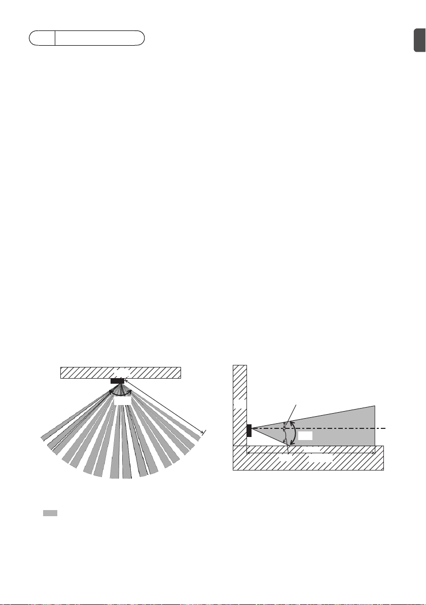
(c) Install the remote controller where occupancy and brightness can be properly detected.
The remote controller has an occupancy sensor and a brightness sensor.
Each sensor has a sensor-detection zone.
• Install the remote controller where the coverage area covers the appropriate area in the room.
The maximum distance the sensor can detect occupancy is approximately 10 m (32 ft).
: Detection area
* As an inherent characteristic of the occupancy sensor, it is more sensitive to movements across
the area indicated by
■ than to movements straight toward the sensor.
5How To Install
Occupancy sensor
Horizontal direction Vertical direction
110°
Remote
controller
Wall
10 m
Figure 1
31°
11°
20°
Remote
controller
Floor
Wall
10 m
Figure 2

– 7 –
Occupancy sensor detects occupancy based on the temperature difference between the occupant
and its surroundings.
To be precise, to enhance the sensitivity of the sensor to occupant movements, the occupancy
sensor is designed to detect the changes in the amount of infrared light emitted from an object in
the detection zone, including human bodies.
The occupancy sensor will not detect occupancy if no movements exist.
The sensor also becomes less sensitive to occupancy when the temperature difference between
the occupant and its surroundings is small.
• Select the installation location carefully to avoid false detection.
Factors that contribute to false detection by the occupancy sensor
• Direct sunlight to the remote controller
• Supply air directed straight toward the remote controller
• Fireplace in the detection zone
• Portable heater (e.g., oscillating electric heater) in the detection zone
• Excessive vibrations or large impact inflicted on the remote controller
• Strong electrical noise
• Movements of small animals, such as cats and dogs
Handling precautions
• Keep the lens scratch-free.
• Do not place adhesive tape or labels over the lens.
• Use a soft cloth to clean the lens.
Brightness sensor
Horizontal direction Vertical direction
44°
Remote
controller
Wall
Figure 3
44°
22°
22°
Remote
controller
Floor
Wall
Figure 4
Do not install the controller in a place where
the difference between the remote controller
surface temperature and the actual room
temperature will be great.
If the temperature difference is too high,
room temperature may not be adequately
controlled.
To avoid deformation and malfunction, do
not install the remote controller in direct
sunlight, where the ambient temperature
may rise above 40ºC (104°F) or drop below
0ºC (32°F), or where the relative humidity
may rise above 90% or drops below 20%.
To reduce the risk of malfunctions, do not
install the controller in a place where water
or oil may come into contact with the
controller, or in a condensing or corrosive
environments.
Do not install the remote controller directly
onto electrically conductive objects such as
metal plate that has not been painted.
To use the Energy Saving Assist function in
a system with both main and sub remote
controllers, activate the function only on the
remote controller whose coverage area is
the largest.
Important
 Loading...