


Mitsubishi Electronics MSY-A15, MSZ-A09, MSZ-D30, MUZ-FE09, MUZ-FD09 User Manual
...
|
|
|
|
|
|
|
|
|
|
|
|
|
|
|
|
|
|
|
|
|
|
|
|
|
|
|
|
|
|
|
|
|
|
|
|
|
|
|
|
|
|
|
|
|
|
|
|
|
|
|
|
|
|
|
|
|
|
|
|
|
|
|
|
|
|
|
|
|
|
|
|
|
|
|
|
|
|
|
|
|
|
|
|
|
|
|
|
|
|
|
|
|
|
Revision G: |
|
|
|
|
|
|
|
|
|
|
|
|
|
|
|
|
|
|
|
|
|
|
|
|
|
|
|
|
|
|
|
|
|
|
|
|
|
|
|
|
|
|
|
|
|
||||
|
|
|
|
|
|
|
|
|
|
|
|
|
|
|
|
|
|
|
|
|
|
• MSZ-FE18NA, MSZ-GE24NA and MSY-GE24NA |
|
|
|
|
|
|
|
|
|
|
|
|
|
|
|
|
|
|
|
|
|
|
|||
|
|
|
|
|
|
|
|
|
|
|
|
|
|
|
|
|
|
|
|
|
|
have been added. |
|
|
|
|
|
|
|
|
|
|
|
|
|
|
|
|
|
|
|
|
|
|
|
|
|
|
|
|
|
|
|
|
|
|
|
|
|
|
|
|
|
|
|
|
|
|
|||
SPLIT-TYPE AIR CONDITIONERS |
|
||||||||||||||||||||||
|
|
|
|
||||||||||||||||||||
|
|
Please void OBT16 REVISED EDITION-F. |
|
||||||||||||||||||||
|
|
|
|
|
|
|
|
|
|
|
|
|
|
|
|
|
|
|
|
|
|
|
|
No. OBT16
REVISED EDITION-G
SERVICE TECHNICAL GUIDE
Models |
· MU-A•WA |
|
MS-A•WA |
||
MSZ-A•NA |
· MUZ-A•NA, - U |
|
MSY-A•NA |
· MUY-A•NA |
|
MSZ-FD•NA |
· MUZ-FD•NA, - U |
|
MSZ-FE•NA |
· MUZ-FE•NA |
|
MSZ-D•NA |
· MUZ-D•NA, - U |
|
MSY-D•NA |
· MUY-D•NA |
|
MSZ-GA•NA |
· MUZ-GA•NA, - U |
|
MSY-GA•NA |
· MUY-GA•NA |
|
MSZ-GE•NA |
· MUZ-GE•NA |
|
MSY-GE•NA |
· MUY-GE•NA |
|
MFZ-KA•NA |
· MXZ-A•NA, - 1 , - 2 |
|
|
· MXZ-B•NA, - 1 |
|
|
|
|
|
|
CONTENTS |
|
|
1. MS MICROPROCESSOR CONTROL·················· 4 |
|
|
2. MSZ, MSY MICROPROCESSOR CONTROL······7 |
|
|
3. MXZ MICROPROCESSOR CONTROL·············· 21 |
|
|
4. MFZ MICROPROCESSOR CONTROL·············· 35 |
CONFIDENTIAL
(FOR INTERNAL USE ONLY)

Revision A:
• MXZ-3A30NA- 1 has been added.
Revision B:
• MXZ-2A20NA- 1 , MXZ-4A36NA, MSZ-FD, MSZ-D and MSY-D have been added.
Revision C:
• MXZ-2A20NA- 2 has been added.
Revision D:
• MSZ-GA•NA and MSY-GA•NA have been added.
Revision E:
• MSZ-FE•NA, MSZ-GE•NA, MSY-GE•NA and MXZ-B•NA have been added.
Revision F:
• MXZ-2B20NA- 1 , MXZ-3B24NA, MXZ-3B30NA, MXZ-4B36NA and MFZ-KA09/12/18NA have been added.
Revision G:
• MSZ-FE18NA, MSZ-GE24NA and MSY-GE24NA have been added.
2

1. MS MICROPROCESSOR CONTROL ··················································································································· 4
Indoor unit models |
Outdoor unit models |
MS-A09/12WA |
MU-A09/12WA |
1-1. COOL OPERATION ······································································································································· 4
1-2. DRY OPERATION ·········································································································································· 4
1-3. AUTO VANE OPERATION····························································································································· 6
2. MSZ, MSY MICROPROCESSOR CONTROL ······································································································· 7
Indoor unit models |
Outdoor unit models |
MSZ-A09/12/15/17/24NA MSY-A15/17/24NA MSZ-FD09/12NA MSZ-FE09/12/18NA MSZ-D30/36NA MSY-D30/36NA MSZ-GA24NA MSY-GA24NA MSZ-GE06/09/12/15/18/24NA MSY-GE09/12/15/18/24NA
MUZ-A09/12/15/17/24NA MUY-A15/17/24NA MUZ-FD09/12NA MUZ-FE09/12/18NA MUZ-D30/36NA MUY-D30/36NA MUZ-GA24NA MUY-GA24NA MUZ-GE09/12/15/18/24NA MUY-GE09/12/15/18/24NA
2-1. COOL OPERATION ······································································································································· 7
2-2. DRY OPERATION ·········································································································································· 8
2-3. HEAT OPERATION ········································································································································ 8 2-4. AUTO CHANGE OVER ··· AUTO MODE OPERATION··············································································· 10 2-5. OUTDOOR FAN MOTOR CONTROL·········································································································· 11 2-6. AUTO VANE OPERATION··························································································································· 11 2-7. INVERTER SYSTEM CONTROL················································································································· 12 2-8. OPERATIONAL FREQUENCY CONTROL OF OUTDOOR UNIT ······························································ 17 2-9. EXPANSION VALVE CONTROL (LEV CONTROL) ···················································································· 18 2-10. PRE-HEAT CONTROL································································································································· 20
3. MXZ MICROPROCESSOR CONTROL··············································································································· 21
Outdoor unit models
MXZ-2A20NA MXZ-3A30NA MXZ-4A36NA
MXZ-2B20NA MXZ-3B24NA
MXZ-3B30NA MXZ-4B36NA
3-1. INVERTER SYSTEM CONTROL················································································································· 21 3-2. EXPANSION VALVE CONTROL (LEV CONTROL) ···················································································· 23 3-3. OPERATIONAL FREQUENCY RANGE ······································································································ 29 3-4. HEAT DEFROSTING CONTROL················································································································· 31 3-5. DISCHARGE TEMPERATURE PROTECTION CONTROL··················································································31
3-6. OUTDOOR FAN CONTROL ························································································································ 32
3-7. PRE-HEAT CONTROL································································································································· 33
3-8. COOL OPERATION···············································································································································33
3-9. DRY OPERATION··················································································································································34
3-10. HEAT OPERATION ······································································································································ 34
4. MFZ MICROPROCESSOR CONTROL ··············································································································· 35
Indoor unit models
MFZ-KA09NA
MFZ-KA12NA
MFZ-KA18NA
4-1. COOL OPERATION ···································································································································· 35
4-2. DRY OPERATION ······································································································································· 35
4-3. HEAT OPERATION ····································································································································· 36 4-4. AUTO CHANGE OVER ··· AUTO MODE OPERATION ············································································· 37 4-5. INDOOR FAN MOTOR CONTROL············································································································· 37 4-6. AUTO VANE OPERATION·························································································································· 38
3

1 
 MS MICROPROCESSOR CONTROL
1-1. COOL ( ) OPERATION
1.Thermostat control
Thermostat turns ON or OFF by the difference between room temperature and set temperature.
|
Room temperature minus |
Room temperature minus |
||||||
Thermostat |
set temperature (Initial) |
set temperature (During operation) |
||||||
ON |
-1.8°F(-1°C) or more |
|
|
|
|
|
|
|
OFF |
less than -1.8°F(-1°C) |
|
|
|
|
|
|
|
|
|
|
|
|
|
|||
-1.8°F |
-1.35°F |
|||||||
|
|
|||||||
|
|
(-1°C) |
(-0.75°C) |
|||||
2.Indoor fan speed control
Indoor fan operates continuously at the set speed by FAN SPEED CONTROL button regardless of the thermostat's OFFON.
In AUTO the fan speed is as follows.
Fan speed |
Room temperature minus |
set temperature (Initial) |
|
High |
3.15°F(1.75°C) or more |
Med. |
between 1.8 and 3.15°F |
Low |
less than 1.8°F(1°C) |
Room temperature minus
set temperature (During operation)
5.4°F
1.8°F 3.15°F (1°C) (1.75°C)
(3°C)
3.Coil frost prevention
 Temperature control
When the indoor coil thermistor RT12 reads 37°F (3°C) or below the coil frost prevention mode starts immediately. However, the coil frost prevention does not work for 5 minutes since the compressor has started.
The indoor fan operates at the set speed and the compressor stops for 5 minutes.
After that, if the indoor coil thermistor still reads below 37°F (3°C), this mode is prolonged until the indoor coil thermistor reads over 37°F (3°C).
 Time control
When the 3 conditions as follows have been satisfied for 1 hour and 45 minutes, compressor stops for 3 minutes.
a.Compressor has been continuously operating.
b.Indoor fan speed is Low or Med.
c.Room temperature is below 79°F (26°C).
When compressor stops, the accumulated time is cancelled and when compressor restarts, time counting starts from the beginning.
Time counting also stops temporarily when the indoor fan speed becomes High or the room temperature exceeds 79°F (26°C). However, when two of the above conditions (b. and c.) are satisfied again, time accumulation is resumed.
Operation chart Example
Compressor |
ON |
|
|
|
|
|
|
|
|
|
|||
|
|
|
|
|
|
|
Outdoor fan |
OFF |
|
|
|
|
|
Indoor fan |
ON |
|
( Continuously at set speed) |
|
||
|
|
|
|
|
||
1-2. DRY ( ) OPERATION
Set temperature is as shown on the right chart.
The system for dry operation uses the same refrigerant circuit as the cooling circuit.
The compressor and the indoor fan are controlled by the room temperature.
By such controls, indoor flow amounts will be reduced in order to lower humidity without much room temperature decrease.
|
|
Set temperature and |
|
|
|
||
|
95 |
initial room temperature in dry mode |
|||||
(°F) |
86 |
|
|
|
|
|
|
|
|
|
|
|
|
|
|
temperature |
77 |
|
|
|
|
|
|
68 |
|
|
|
|
|
|
|
Set |
|
|
|
|
|
|
|
|
59 |
|
|
|
|
|
|
|
5050 |
59 |
68 |
77 |
86 |
95 |
|
|
|
|
Initial room temperature (°F) |
|
|||
4

1.Thermostat control
Thermostat turns ON or OFF by the difference between room temperature and set temperature.
|
Room temperature minus |
Thermostat |
set temperature (Initial) |
ON |
-3.6°F(-2°C) or more |
OFF |
less than -3.6°F(-2°C) |
2.Indoor fan speed control
Indoor fan operates at the set speed by FAN SPEED CONTROL button. When thermostat OFF (compressor OFF), fan speed becomes Very Low. In AUTO the fan speed is as follows.
Room temperature minus
set temperature (During operation)
-3.6°F -1.35°F (-2°C) (-0.75°C)
Fan speed |
Room temperature minus |
Room temperature minus |
||||||
set temperature (Initial) |
set temperature (During operation) |
|||||||
High |
3.15°F(1.75°C) or more |
|
|
|
|
|
|
|
|
|
|
|
|
|
|
||
Med. |
between 1.8 and 3.15°F |
|
|
|
|
|
|
|
|
|
|
|
|
|
|
||
|
|
|
|
4.5°F |
||||
Low |
less than 1.8°F(1°C) |
|
|
|
|
|||
1.8°F |
3.15°F (2.5°C) |
|||||||
|
|
(1°C) |
(1.75°C) |
|||||
3.The operation of the compressor and indoor/outdoor fan
Compressor operates by room temperature control and time control.
Set temperature is controlled to fall 4°F (2°C) from initial room temperature. Indoor fan and outdoor fan operate in the same cycle as the compressor.
•When the room temperature is 73°F (23°C) or over:
•When The Thermostat is ON, the compressor repeats 8 minutes ON and 3 minutes OFF.
•When The thermostat is OFF, the compressor repeats 4 minutes OFF and 1 minute ON.
•When the room temperature is under 73°F (23°C).
•When The Thermostat is ON, the compressor repeats 2 minutes ON and 3 minutes OFF.
•When The thermostat is OFF, the compressor repeats 4 minutes OFF and 1 minute ON.
Operation time chart
Example
ON
Thermostat
OFF
ON
Indoor fan
OFF
Outdoor fan ON
Compressor
OFF
8 minutes |
3 minutes 4 minutes 1 minute |
4.Coil frost prevention
Coil frost prevention is as same as COOL mode. (2-1.3.)
The indoor fan maintains the actual speed of the moment. However, when coil frost prevention works while the compressor is not operating, its speed becomes the set speed.
5

1-3. AUTO VANE OPERATION
1. Horizontal vane
ECONO COOL (  ) operation (ECONOmical operation)
When ECONO COOL button is pressed in COOL mode, set temperature is automatically set 3.6°F (2°C) higher than that in COOL mode.
Also the horizontal vane swings in various cycle according to the temperature of indoor heat exchanger (indoor coil thermistor).
SWING operation makes you feel cooler than set temperature. So, even though the set temperature is higher than that in COOL mode, the air conditioner can keep comfort. As a result, energy can be saved.
To cancel this operation, select a different mode or press one of the following buttons in ECONO COOL operation: ECONO COOL or VANE CONTROL button.
<SWING operation>
In swing operation of ECONO COOL operation mode, the initial air flow direction is adjusted to “Horizontal”.
According to the temperature of indoor coil thermistor at starting of this operation, next downward blow time is decided. Then when the downward blow has been finished, next horizontal blow time is decided.
For initial 10 minutes the swing operation is performed in table G~H for quick cooling.
Also, after 10 minutes when the difference of set temperature and room temperature is more than 3.6°F (2°C), the swing operation is performed in table D~H for more cooling.
The air conditioner repeats the swing operation in various cycle as follows.
|
Temperature of indoor |
Downward blow time |
Horizontal blow time |
|
coil thermistor (°F/°C) |
(second) |
(second) |
A |
59/15 or less |
2 |
23 |
B |
59/15 to 63 /17 |
5 |
20 |
C |
63/17/ to 64/18 |
8 |
17 |
D |
64/18 to 68/20 |
11 |
14 |
E |
68/20 to 70/21 |
14 |
11 |
F |
70/21 to 72/22 |
17 |
8 |
G |
72/22 to 75/24 |
20 |
5 |
H |
more than 75/24 |
23 |
2 |
6
2 
 MSZ, MSY MICROPROCESSOR CONTROL
2-1. COOL (  ) OPERATION
1.Thermostat control
Thermostat turns ON or OFF by the difference between room temperature and set temperature.
|
Room temperature minus |
Room temperature minus |
||||||
Thermostat |
set temperature (Initial) |
set temperature (During operation) |
||||||
ON |
-1.8°F(-1°C) or more |
|
|
|
|
|
|
|
OFF |
less than -1.8°F(-1°C) |
|
|
|
|
|
|
|
|
|
|
|
|
|
|||
-1.8°F |
-1.35°F |
|||||||
|
|
|||||||
|
|
(-1°C) |
(-0.75°C) |
|||||
2.Indoor fan speed control
Indoor fan operates continuously at the set speed by FAN SPEED CONTROL button regardless of the thermostat's OFFON.
In AUTO the fan speed is as follows.
Fan speed |
Room temperature minus |
set temperature (Initial) |
|
High |
3.15°F(1.75°C) or more |
Med. |
between 1.8 and 3.15°F |
Low |
less than 1.8°F(1°C) |
Room temperature minus
set temperature (During operation)
5.4°F
1.8°F 3.15°F (1°C) (1.75°C)
(3°C)
3.Coil frost prevention
The compressor operational frequency is controlled to prevent the temperature of indoor heat exchanger from falling excessively.
The compressor is turned OFF for 5 minutes when the temperature of indoor coil thermistor continues 37°F (3°C) or less for 5 minutes or more.
The indoor fan maintains the actual speed of the moment.
4.Low outside temperature operation
If the outside temperature falls to 64°F (18°C) or less during operation in COOL mode, the unit will switch to the low outside temperature operation mode.
<Operation>
(1)Outdoor fan control
The outdoor fan rotational speed slows down to maintain sufficient cooling capacity.
NOTE: Even when the unit is in the "thermostat-off" status under the low outside temperature operation mode, the outdoor fan rotation does not stop.
(2)Dew drop prevention
When the ambient temperature thermistor reads 14°F (-10°C) or less (the set temperature is different depending on the models), as coil frost or dew drop from indoor unit may occur, the compressor turns OFF with the outdoor fan OFF for prevention of them.
(3)Outdoor temperature detecting control
To detect the exact outdoor temperature in this mode, the compressor turns OFF but the outdoor fan stays ON for 3
minutes once 1 hour. If the outdoor temperature rises over about 64°F (18°C), the unit goes back to the normal COOL mode. If the outside temperature stays below about 64°F (18°C), the unit continues to run in the low outside temperature operation mode.
 Other protections work as well as in the normal COOL mode.
7

2-2. DRY (  ) OPERATION
Set temperature is as shown on the right chart.
The system for dry operation uses the same refrigerant circuit as the cooling circuit.
The compressor and the indoor fan are controlled by the room temperature.
By such controls, indoor flow amounts will be reduced in order to lower humidity without much room temperature decrease.
1. Thermostat control
|
|
Set temperature and |
|
|
|
||
|
95 |
initial room temperature in dry mode |
|||||
(°F) |
86 |
|
|
|
|
|
|
|
|
|
|
|
|
|
|
temperature |
77 |
|
|
|
|
|
|
68 |
|
|
|
|
|
|
|
Set |
|
|
|
|
|
|
|
|
59 |
|
|
|
|
|
|
|
5050 |
59 |
68 |
77 |
86 |
95 |
|
|
|
|
Initial room temperature (°F) |
|
|||
Thermostat turns ON or OFF by the difference between room temperature and set temperature.
|
Room temperature minus |
Thermostat |
set temperature (Initial) |
ON |
-3.6°F(-2°C) or more |
OFF |
less than -3.6°F(-2°C) |
2.Indoor fan speed control
Indoor fan operates at the set speed by FAN SPEED CONTROL button.
When the thermostat turns OFF (compressor OFF), fan speed becomes Very Low. In AUTO the fan speed is as follows.
Room temperature minus
set temperature (During operation)
-3.6°F -1.35°F (-2°C) (-0.75°C)
Fan speed |
Room temperature minus |
set temperature (Initial) |
|
High |
3.15°F(1.75°C) or more |
Med. |
between 1.8 and 3.15°F |
Low |
less than 1.8°F(1°C) |
3.Coil frost prevention
Coil frost prevention is as same as COOL mode. (2-1.3.)
Room temperature minus
set temperature (During operation)
4.5°F 1.8°F 3.15°F (2.5°C) (1°C) (1.75°C)
The indoor fan maintains the actual speed of the moment. However, when coil frost prevention works while the compressor is not operating, its speed becomes the set speed.
4.Low outside temperature operation
Low outside temperature operation is as same as COOL mode. (2-1.4.)
2-3. HEAT (  ) OPERATION (MSZ)
1.Thermostat control
Thermostat turns ON or OFF by difference between room temperature and set temperature.
(MSZ-FE18 MSZ-GE24) |
Thermostat |
Room temperature minus |
set temperature (Initial) |
||
|
ON |
less than 1.8°F(1°C) |
|
OFF |
1.8°F(1°C) or more |
(Other models) |
Thermostat |
Room temperature minus |
set temperature (Initial) |
||
|
ON |
less than 3.6°F(2°C) |
|
OFF |
3.6°F(2°C) or more |
2.Indoor fan speed control
(1)Indoor fan operates at the set speed by FAN SPEED CONTROL button. In Auto the fan speed is as follows.
Room temperature minus
set temperature (During operation)
1.35°F 1.8°F (0.75°C) (1°C)
Room temperature minus
set temperature (During operation)
3.15°F 3.6°F (1.75°C) (2°C)
Fan speed |
Set temperature minus |
Set temperature minus room |
||||||||
room temperature (Initial) |
temperature (During operation) |
|||||||||
|
|
|
|
|
3.6°F |
7.2°F |
||||
High |
3.6°F(2°C) or more |
|
|
|
(2°C) |
(4°C) |
||||
|
|
|
|
|
|
|
|
|
||
Med. |
Between 0.45 and 3.6°F |
|
|
|
|
|
|
|
|
|
|
|
|
|
|
|
|
|
|
||
Low |
Less than 0.45°F(0.25°C) |
|
|
|
|
|
|
|
|
|
|
|
|
|
|
|
|
|
|
||
0.45°F |
3.15°F |
|
|
|
||||||
|
|
|
|
|
||||||
|
|
(0.25°C) |
(1.75°C) |
|
|
|
||||
8
(2)Cold air prevention control
MSZ-A09/12/15/17 MSZ-FD MSZ-FE MSZ-D MSZ-GE
 When the compressor is not operating,
( |
) if the temperature of room temperature thermistor is less than 66°F (19°C), the fan stops. |
|
( |
) if the temperature of room temperature thermistor is 66°F (19°C) or more and |
|
|
( |
) if the temperature of indoor coil thermistor is less than 32°F (0°C), the fan stops. |
|
( |
) if the temperature of indoor coil thermistor is 32°F (0°C) or more, the fan operates at Very Low. |
When the compressor is operating, |
||
( |
) if the temperature of indoor coil thermistor is 104°F (40°C) or more, the fan operates at set speed. |
|
( |
) if the temperature of indoor coil thermistor is less than 104°F (40°C) and |
|
|
( |
) if heating operation starts after defrosting, the fan stops. |
|
( |
) if the temperature of room temperature thermistor is 66°F (19°C) or less, the fan stops. |
|
( |
) if the temperature of room temperature thermistor is more than 66°F (19°C), the fan operates at Very Low. |
NOTE: When 4 minutes (MSZ-FE18 MSZ-GE24)/3 minutes (Other models) have passed since the compressor started operation, this control is released regardless of the temperature of room temperature thermistor and indoor coil thermistor.
MSZ-A24 MSZ-GA
 When the compressor is not operating,
( |
) if the temperature of room temperature thermistor is 59°F (15°C) or less, or temperature of indoor coil thermis- |
|
tor is less than 64°F (18°C), the fan stops. |
( |
) if the temperature of room temperature thermistor is more than 59°F (15°C), or temperature of indoor coil |
|
thermistor is more than 64°F (18°C), the fan operates at Very Low. |
 When the compressor is operating,
( |
) if the temperature of indoor coil thermistor is 64°F (18°C) or more, the fan operates at set speed. |
|
( |
) if the temperature of indoor coil thermistor is less than 64°F (18°C) and |
|
|
( |
) if heating operation starts after defrosting, the fan stops. |
|
( |
) if the temperature of room temperature thermistor is 59°F (15°C) or less, the fan stops. |
|
( |
) if the temperature of room temperature thermistor is more than 59°F (15°C), the fan operates at Very Low. |
NOTE: When 3 minutes have passed since the compressor started operation, this control is released regardless of the temperature of room temperature thermistor and indoor coil thermistor.
(3)Warm air control (MSZ-FD MSZ-FE MSZ-GE)
When the following any condition of  (a. ~ c.) and the condition of
  are satisfied at the same time, warm air control works.
 a.) Fan speed is used in MANUAL.
b.) When cold air prevention has been released. c.) When defrosting has been finished.
 When the temperature of indoor coil thermistor is less than 104°F (40°C).
When warm air control works, the fan speed changes as follows to blow out warm air gradually.
Gradation of fan speed in initial
(MSZ-FE18 MSZ-GE24) |
<Time condition> |
<Indoor fan speed> |
|
Less than 4 minutes------------ |
Low |
|
4 to 8 minutes-------------------- |
Med. |
|
More than 8 minutes ----------- |
High |
(Other models) |
<Time condition> |
<Indoor fan speed> |
|
Less than 2 minutes------------ |
Low |
|
2 to 4 minutes-------------------- |
Med. |
|
More than 4 minutes ----------- |
High or Super high |
The upper limit of the fan speed in MANUAL is the set speed.
When the temperature of indoor coil thermistor has been 104°F (40°C) or more, or when the set speed has been changed, this control is released and the fan speed is the set speed.
3. Overload starting
When the room temperature thermistor reads 64°F (18°C) or more, the compressor runs with its maximum frequency regulated for 10 minutes after the start-up.
4.Defrosting
(1)Starting conditions of defrosting
When the following conditions a) ~ c) are satisfied, the defrosting starts.
a)The defrost thermistor reads about 30.2°F (-1°C) or less.
b)The cumulative operation time of the compressor has reached any of the set values (defrost interval: 40-150 minutes).
c)More than 5 minutes have passed since the start-up of the compressor.
 The defrost interval is decided by the previous defrosting time. The next defrost interval extends or shortens 0-20 minutes compared with the previous defrost interval.
9
(2) Releasing conditions of defrosting
Defrosting is released when any one of the following conditions is satisfied:
a)The defrost thermistor continues to read "Defrost finish temperature" for 30 seconds.
Refer to "CHANGE IN DEFROST SETTING of SERVICE FUNCTIONS in OUTDOOR UNIT SERVICE MANUAL".
b)Defrosting time has exceeded 10 minutes.
c)Any other mode than HEAT mode is set during defrosting.
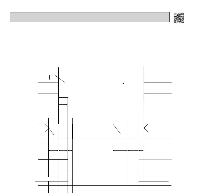
Time chart of defrosting in HEAT mode (reverse type)
<Indoor unit>
Horizontal vane
Indoor fan
set position
set speed
horizontal
horizontal (temperature of indoor coil thermistor < 102 °F) (39°C)
Very Low (temperature of indoor coil thermistor > 64 °F)
OFF |
(18°C) |
|
set position
set speed
|
|
30 |
|
|
|
|
|
seconds |
|
|
|
<Outdoor unit> |
|
|
|
|
|
|
|
|
Maximum frequency |
|
|
Compressor normal |
|
|
|
|
|
|
|
OFF |
|
|
OFF |
|
40 |
30 |
|
40 |
30 |
|
seconds seconds |
5 seconds |
seconds |
seconds |
|
|
|
|
|
|
|
|
ON |
|
|
|
|
Outdoor fan |
|
|
|
|
|
|
|
|
OFF |
|
|
R.V. coil |
ON (HEAT) |
|
|
|
|
|
|
OFF (COOL) |
|
|
|
(21S4) |
|
|
|
|
|
|
|
|
|
|
|
5 seconds
ON
ON (HEAT)
2-4. AUTO CHANGE OVER ··· AUTO MODE OPERATION (MSZ)
Once desired temperature is set, unit operation is switched automatically between COOL and HEAT operation.
1.Mode selection
(1)Initial mode
At first indoor unit operates only indoor fan with outdoor unit OFF for 3 minutes to detect present room temperature. Following the conditions below, operation mode is selected.
 If the room temperature thermistor reads more than set temperature, COOL mode is selected.
  If the room temperature thermistor reads set temperature or less, HEAT mode is selected.
10
(2)Mode change
In case of the following conditions, the operation mode is changed.
 COOL mode changes to HEAT mode when 15 minutes have passed with the room temperature 2 - 4°F (1 - 2°C) below the set temperature.
 HEAT mode changes to COOL mode when 15 minutes have passed with the room temperature 2 - 4°F (1 - 2°C) above the set temperature.
In the other cases than the above conditions, the present operation mode is continued.
NOTE1: Mode selection is performed when multi standby (refer to NOTE2) is released and the unit starts operation with ON-timer.
NOTE2: When two or more indoor units are operating simultaneously, the indoor unit, which is operating in AUTO ( 
 ), might not be able to change over the operating mode (COOL ↔ HEAT) and becomes the standby state.
(3)Indoor fan control/ Vane control
As the indoor fan speed and the horizontal vane position depend on the selected operation mode, when the operation mode changes over, they change to the exclusive ones.
2-5. OUTDOOR FAN MOTOR CONTROL
Fan speed is switched according to the compressor frequency. |
|
|
|||||||
Fan speed |
|
|
|
<Relation between compressor frequency and fan speed> |
|
||||
|
Down |
Up |
|
|
|
||||
High |
|
Compressor frequency (Hz) |
|||||||
|
|
|
|
|
|
||||
|
|
|
|
|
|
|
Down |
Up |
|
Low |
|
|
|
|
|
MUZ-A MUY-A |
|
|
|
|
|
|
|
|
|
|
|||
|
|
|
|
|
MUZ-FD |
|
|
||
Min. Compressor frequency Max. |
33 |
44 |
|||||||
|
MUZ-FE09/12 |
||||||||
|
|
|
|
|
|
MUZ-GA MUY-GA |
|
|
|
|
|
|
|
|
|
MUZ-GE12/15/18 MUY-GE12/15/18 |
|
|
|
|
|
|
|
|
|
MUZ-D MUY-D |
39 |
54 |
|
|
|
|
|
|
|
MUZ-GE09 MUY-GE09 |
|||
|
|
|
|
|
|
|
|
||
|
|
|
|
|
|
MUZ-FE18 |
33 |
43 |
|
|
|
|
|
|
|
MUZ-GE24 MUY-GE24 |
|||
|
|
|
|
|
|
|
|
||
2-6. AUTO VANE OPERATION
1. Horizontal vane
(1) Cold air prevention in HEAT operation (MUZ)
When any of the following conditions occur in HEAT operation, the vane angle changes to Horizontal position automatically to prevent cold air blowing on users.
 Compressor is not operating.
 Defrosting is performed.
 Indoor coil thermistor temperature does not exceed 102°F (39°C) within about 3 minutes after compressor starts. NOTE: When 2 or more indoor units are operated with multi outdoor unit, even if any indoor unit turns thermostat OFF,
this control does not work in the indoor unit.
(2)ECONO COOL (  ) operation (ECONOmical operation) (Excluding MSZ-FD and MSZ-FE09/12)
When ECONO COOL button is pressed in COOL mode, set temperature is automatically set 3.6°F (2°C) higher than that in COOL mode.
Also the horizontal vane swings in various cycle according to the temperature of indoor heat exchanger (indoor coil thermistor).
SWING operation makes you feel cooler than set temperature. So, even though the set temperature is higher than that in COOL mode, the air conditioner can keep comfort. As a result, energy can be saved.
To cancel this operation, select a different mode or press one of the following buttons in ECONO COOL operation: ECONO COOL or VANE CONTROL button.
11
<SWING operation>
In swing operation of ECONO COOL operation mode, the initial air flow direction is adjusted to “Horizontal”. According to the temperature of indoor coil thermistor RT12 at starting of this operation, next downward blow time is decided. Then when the downward blow has been finished, next horizontal blow time is decided.
For initial 10 minutes the swing operation is performed in table G~H for quick cooling.
Also, after 10 minutes when the difference of set temperature and room temperature is more than 3.6°F (2°C), the swing operation is performed in table D~H for more cooling.
The air conditioner repeats the swing operation in various cycle as follows.
|
Temperature of indoor |
Downward blow time |
Horizontal blow time |
|
coil thermistor (°F/°C) |
(second) |
(second) |
A |
59/15 or less |
2 |
23 |
B |
59/15 to 63/17 |
5 |
20 |
C |
63/17 to 64/18 |
8 |
17 |
D |
64/18 to 68/20 |
11 |
14 |
E |
68/20 to 70/21 |
14 |
11 |
F |
70/21 to 72/22 |
17 |
8 |
G |
72/22 to 75/24 |
20 |
5 |
H |
more than 75/24 |
23 |
2 |
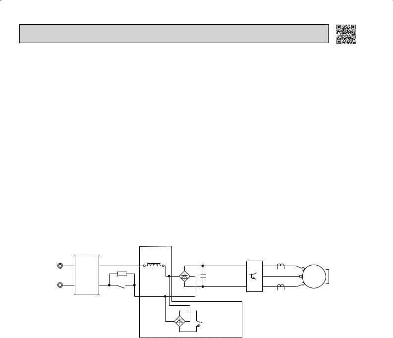
2-7. INVERTER SYSTEM CONTROL
2-7-1. Inverter main power supply circuit
MUZ-A09/12/15/17 MUY-A15/17 MUZ-FD MUZ-FE09/12 MSZ-GE06/09/12/15/18 MUY-GE09/12/15/18
|
|
|
DIODE |
|
|
CURRENT |
||
|
|
REACTOR |
|
|
TRANSFORMER |
|||
|
|
MODULE1 |
P |
U |
U |
|||
|
NOISE |
RESISTOR |
||||||
POWER |
~ |
+ |
~ |
+ SMOOTHING |
|
MS |
||
FILTER |
|
|
V |
|||||
SUPPLY |
CIRCUIT |
|
|
- |
|
CAPACITOR |
V 3~ |
|
|
|
|
|
W |
||||
|
|
RELAY |
|
|
|
N |
W |
|
|
|
|
|
|
IPM |
|||
|
|
|
|
|
COMPRESSOR |
|||
|
|
|
|
|
|
|||
|
|
~ + |
|
~ |
SWITCHING |
|
|
|
|
|
DIODE |
- |
|
|
POWER |
|
|
|
|
MODULE2 |
|
|
TRANSISTOR |
|
|
|
BOOSTER CHOPPER CIRCUIT
Function of main parts
|
NAME |
FUNCTION |
|
|
|
|
|
INTELLIGENT POWER MODULE (IPM) |
It supplies 3-phase AC power to compressor. |
||
|
|
|
|
SMOOTHING CAPACITOR |
It stabilizes the DC voltage and supplies it to IPM. |
||
|
|
|
|
CURRENT TRANSFORMER |
It measures the current of the compressor motor. |
||
|
|
|
|
DIODE MODULE 1 |
It converts the AC voltage to DC voltage. |
||
|
|
|
|
RESISTOR |
It absorbs the rush current not to run into the main power supply circuit when |
||
the electricity turns ON. |
|||
|
|
||
RELAY |
It keeps the RESISTOR, which restricts rush current, short-circuited while the |
||
compressor is operating. |
|||
|
|
||
BOOSTER |
DIODE MODULE 2 |
|
|
|
It improves power factor. |
||
|
|||
CHOPPER |
SWITCHING POWER TRANSISTOR |
||
CIRCUIT |
|
It controls the bus-bar voltage. |
|
REACTOR |
|
||
|
|
||
|
|
|
|
12
 Loading...