


MSZ-GE18NA
Mitsubishi MSZ-GE18NA, MSZ-GE24NA, MSZ-GE15NA, MSZ-GE09NA, MSZ-GE09NA-8 Installation Guide
...
DIAMONDBACK
The DPLS1 Drain Pan Level Sensor / Control provides protection against drain pan overflow in
Mitsubishi Electric Mr. Slim and CiTY MULTi indoor Units. The unit will sense a high condensate
level in the drain pan. Should this occur the control shuts down the indoor unit before an overflow
can occur. A thermistor error code will be produced should the DPLS1 activate indicating a fault
which must be resolved before the unit will re=start.
This unit provides electronic overflow protection for Drain Pans in all Mr. Slim and CiTY MULTi
indoor units: MFZ, MS, MSY/Z, SEZ, SLZ, PCA/PCFY, PDFY, PEA/PEAD/PEFY, PKA/PKFY, PLA,
PLKA/PLFY, PMFY, and PVFY.
Meets requirements as listed alternative to secondary drain pans in all indoor unit installations
covered by the International Mechanical Code and adaptations.
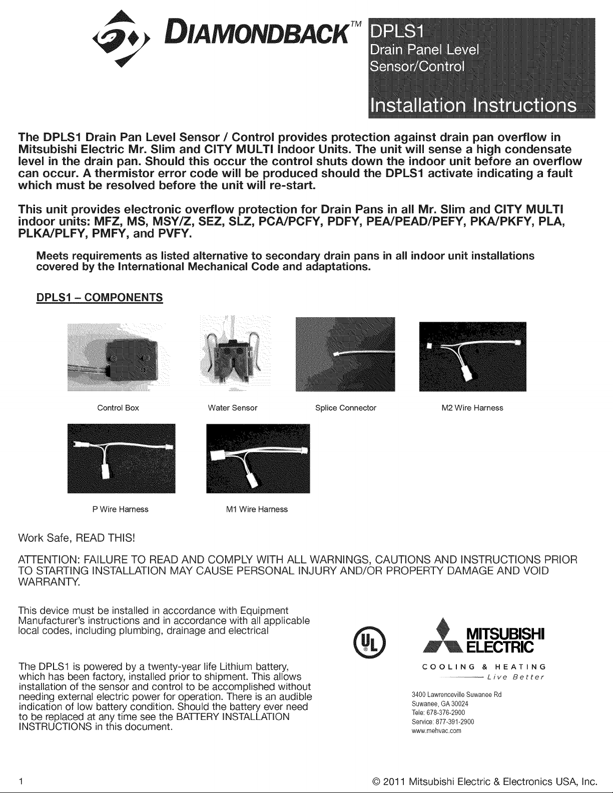
DPLS1 = COMPONENTS
Control Box Water Sensor Splice Connector
M2 Wire Harness
P Wire Harness M1 Wire Harness
Work Safe, READ THIS!
ATTENTION: FAILURE TO READ AND COMPLY WITH ALL WARNINGS, CAUTIONS AND INSTRUCTIONS PRIOR
TO STARTING INSTALLATION MAY CAUSE PERSONAL INJURY AND/OR PROPERTY DAMAGE AND VOID
WARRANTY.
This device must be installed in accordance with Equipment
Manufacturer's instructions and in accordance with all applicable
local codes, including plumbing, drainage and electrical
The DPLS1 is powered by a twenty-year life Lithium battery,
which has been factory, installed prior to shipment. This allows
installation of the sensor and control to be accomplished without
needing external electric power for operation. There is an audible
indication of low battery condition. Should the battery ever need
to be replaced at any time see the BA-FrERY INSTALLATION
INSTRUCTIONS in this document.
®
2 ITSUBISHI
ELECTRIC
COOLING & HEATING
Live Better
3400 Lawrenceville Suwanee Rd
Suwanee, GA 30024
Tele: 678-376-2900
Service: 877-391-2900
www.mehvac.com
1 © 2011 Mitsubishi Electric & Electronics USA, Inc.
DIAMONDBACK
DPLS1 Drain Panel Level Sensor/Control
Protected under one or more patents
© 2011 Mitsubishi Electric & Electronics USA, Inc.
@
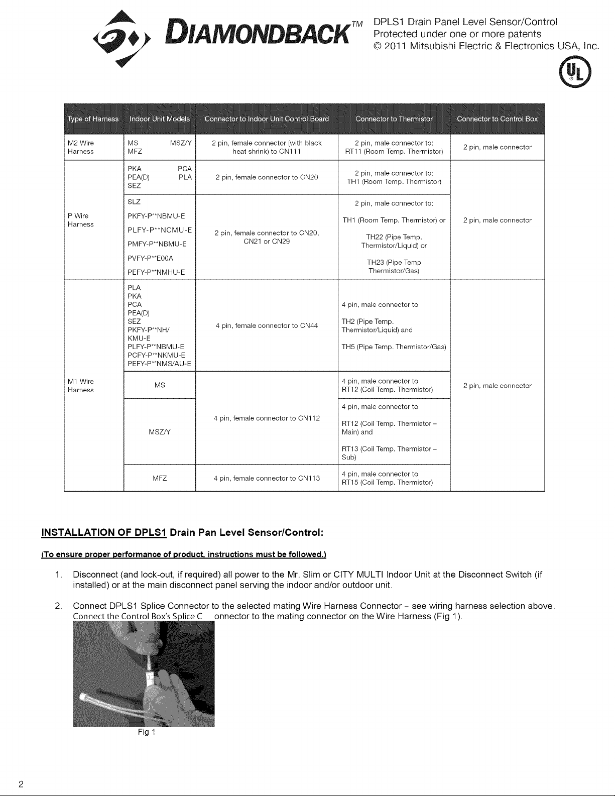
M2 Wire MS 2 pin, female connector (with black 2 pin, male connector to:
Harness MFZ heat shrink) to CN111 AT11 (Room Temp. Thermistor) 2 pin, male connector
P Wire
Harness
M1 Wire
Harness
PKA
PEA(D)
SEZ
SLZ
MSZ/Y
PCA
PLA
2 pin, female connector to CN20
2 pin, male connector to:
TH1 (Room Temp. Thermistor)
2 pin, male connector to:
PKFY-P**NBMU-E
PLFY-P**NCMU-E
PMFY-P**NBMU-E
PVFY-P**E00A
PEFY-P**NMHU-E
PLA
PKA
PCA
PEA(D)
SEZ
PKFY-P**NH/
KMU-E
PLFY-P**NBMU-E
PCFY-P**NKMU-E
PEFY-P**NMS/AU-E
MS
MSZ/Y
MFZ
2 pin, female connector to CN20,
CN21 or CN29
4 pin, female connector to CN44
4 pin, female connector to CN112
4 pin, female connector to CN113
TH1 (Room Temp. Thermistor) or
TH22 (Pipe Temp.
Thermistor/Liquid) or
TH23 (Pipe Temp
Thermistor/Gas)
4 pin, male connector to
TH2 (Pipe Temp.
Thermistor/Liquid) and
TH5 (Pipe Temp. Thermistor/Gas)
4 pin, male connector to
AT12 (Coil Temp. Thermistor)
4 pin, male connector to
AT12 (Coil Temp. Thermistor -
Main) and
AT13 (Coil Temp. Thermistor -
Sub)
4 pin, male connector to
AT15 (Coil Temp. Thermistor)
2 pin, male connector
2 pin, male connector
INSTALLATION OF DPLS1 Drain Pan Level Sensor/Control:
(To ensure proper performance of product, instructions must be followed.)
1. Disconnect (and lock-out, if required) all power to the Mr. Slim or CITY MULTI Indoor Unit at the Disconnect Switch (if
installed) or at the main disconnect panel serving the indoor and/or outdoor unit.
2. Connect DPLSl Splice Connector to the selected mating Wire Harness Connector- see wiring harness selection above.
Connect the Control Box's S)lice C onnector to the mating connector on the Wire Harness (Fig 1).
Fig 1
DIAMONDBACK
DPLS1 Drain Panel Level Sensor/Control
Protected under one or more patents
© 2011 Mitsubishi Electric & Electronics USA, Inc.
®
Typical Installation - example: Wall Mount Indoor Unit - MSIMSYIMSZIPKAIPKFY:
1. Remove front cover of indoor unit in order to expose the coil and the control circuit area of the unit (Fig 2). The disassembly
of the front cover, air filters, and possibly electrical shields will vary according to style of indoor unit installed. See the
Mitsubishi Electric'sTechnical Manual for detailed disassembl'
2,
Fig 2: Typical indoor unit with cover removed
Locate the corresponding connector (see Table 1) on the printed control circuit board and, remove the connector of the
thermistor (Fig 4). Plug female connector of the Wire Harness into the printed circuit board, and plug the male connector on
the opposite end into the thermistor connector (Fig
THERMISTOR CONNECTION TO
PRINTED CIRCUIT BOARD MAY
BE UNDER METAL COVER
OR WITHIN PLASTIC
HOUSING OF INDOOR
Fig 3 Fig 4 Fig 5
3. Determine the best location for the DPLS1 Control Box: Using the double-sided tape, mount the Control Box in a location
inside the indoor unit that will allow clearance for the cover to be reassembled (Fig 6).
MOUNT CONTROL BOX IN
AN AREA VVHERE THE FRONT
COVER WiLL NOT INTERFERE
WHEN REASSEMBLED,
4.
5.
6.
Fig 6
Reassemble any covers that were removed during the installation.
Test the DPLSI: Reconnect power to the indoor unit. Use extreme caution, the DPLS1 is a low voltage device however; do
not make contact with any high voltages on the indoor unit during testing. Turn unit on and set cooling thermostat to lowest
temperature setting. Make sure to restore power to the outdoor unit before performing the test in step 8.
Using a screwdriver or other metallic object, carefully make a connection between the two pins on the Water Sensor (Fig 7).
Indoor unit should shut down after a short delay.
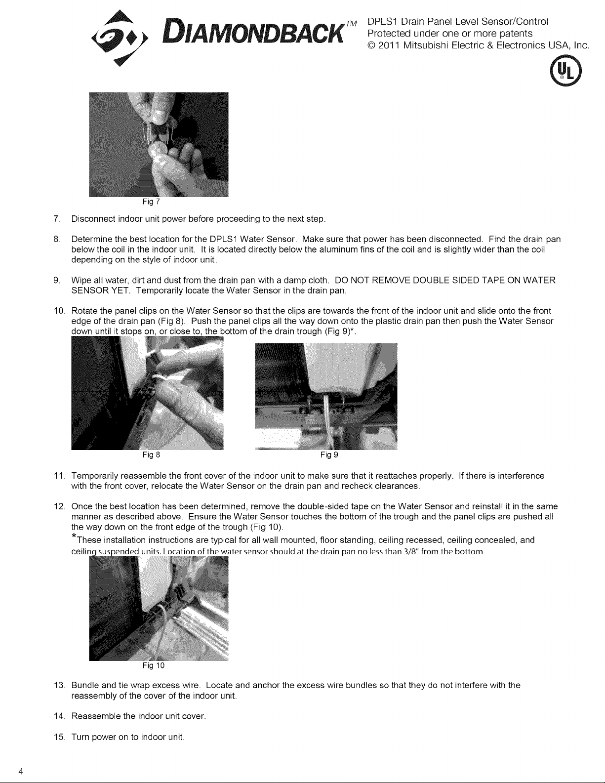
Fig 7
DIAMONDBACK
DPLSl Drain Panel Level Sensor/Control
Protected under one or more patents
© 2011 Mitsubishi Electric & Electronics USA, Inc.
@
7,
8.
9,
10.
Disconnect indoor unit power before proceeding to the next step.
Determine the best location for the DPLS1 Water Sensor. Make sure that power has been disconnected. Find the drain pan
below the coil in the indoor unit. It is located directly below the aluminum fins of the coil and is slightly wider than the coil
depending on the style of indoor unit.
Wipe all water, dirt and dust from the drain pan with a damp cloth. DO NOT REMOVE DOUBLE SIDED TAPE ON WATER
SENSOR YET. Temporarily locate the Water Sensor in the drain pan.
Rotate the panel clips on the Water Sensor so that the clips are towards the front of the indoor unit and slide onto the front
edge of the drain pan (Fig 8). Push the panel clips all the way down onto the plastic drain pan then push the Water Sensor
down until it sto on, or close to, the bottom of the drain trough (Fig 9)*.
Fig 8 Fig 9
11. Temporarily reassemble the front cover of the indoor unit to make sure that it reattaches properly. If there is interference
with the front cover, relocate the Water Sensor on the drain pan and recheck clearances.
12. Once the best location has been determined, remove the double-sided tape on the Water Sensor and reinstall it in the same
manner as described above. Ensure the Water Sensor touches the bottom of the trough and the panel clips are pushed all
the way down on the front edge of the trough (Fig 10).
*These installation instructions are typical for all wall mounted, floor standing, ceiling recessed, ceiling concealed, and
ceiling suspended units. Location of the water sensor should at the drain pan no lessthan 3/8" from the bottom
Fig 10
13. Bundle and tie wrap excess wire. Locate and anchor the excess wire bundles so that they do not interfere with the
reassembly of the cover of the indoor unit.
14. Reassemble the indoor unit cover.
15. Turn power on to indoor unit.
 Loading...