


MSZ-G09SV
SPLIT-TYPE, HEAT PUMP AIR CONDITIONERS
SERVICE MANUAL
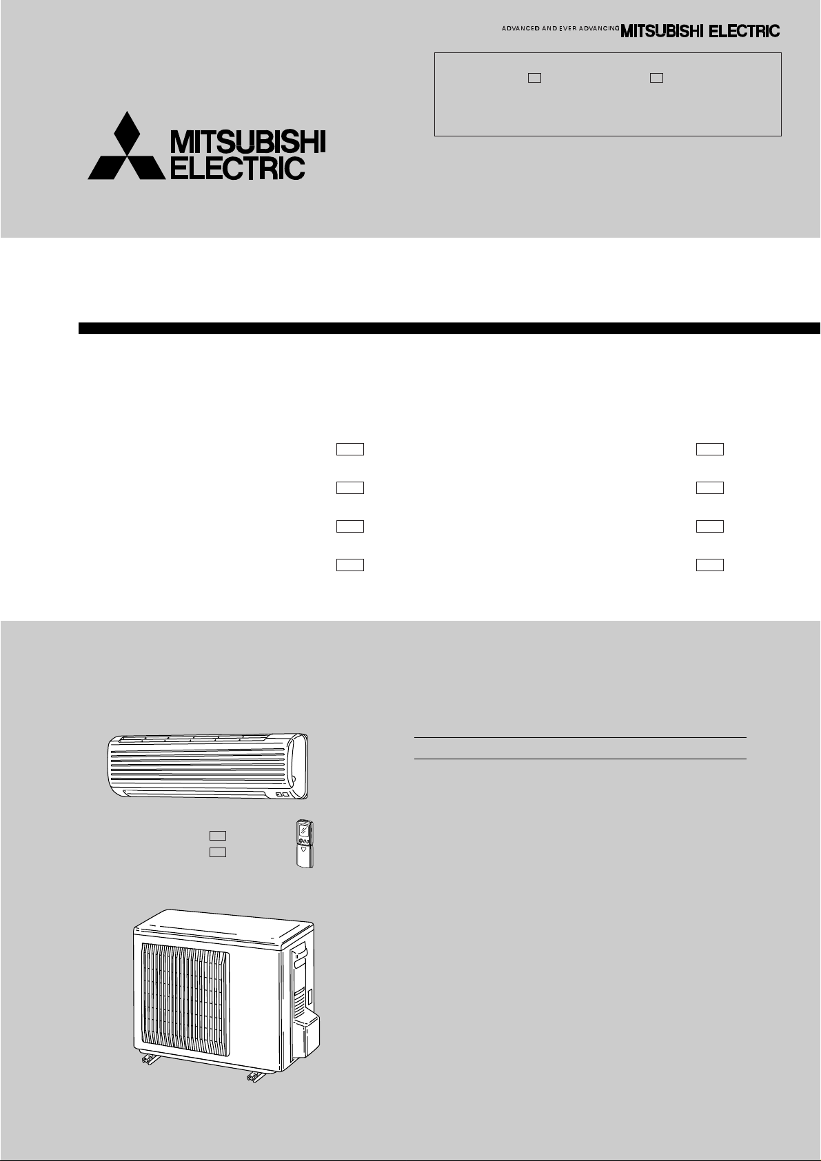
Wireless type
Models
Revision:
●MSZ-G09SV - and MSZ-G12SV - have been added.
●MICROPROCESSOR CONTROL, SERVICE FUNCTIONS,
and PARTS LIST have been partially modified.
●Please void OB245.
E2E2
No. OB245
REVISED EDITION-A
MSZ-G09SV -
MSZ-G09SV MSZ-G12SV MSZ-G12SV -
MSZ-G09SV MSZ-G12SV -
E2
E2
(WH) ●
(WH) ●
(WH) ●
(WH) ●
CONTENTS
1. TECHNICAL CHANGES····································2
2. PART NAMES AND FUNCTIONS······················2
3. SPECIFICATION·················································5
4. NOISE CRITERIA CURVES·······························7
5. OUTLINES AND DIMENSIONS·························8
6. WIRING DIAGRAM···········································11
7. REFRIGERANT SYSTEM DIAGRAM··············14
8. PERFORMANCE CURVES······························16
9. MICROPROCESSOR CONTROL ····················26
10. SERVICE FUNCTIONS·····································41
11. TROUBLESHOOTING ······································44
12. DISASSEMBLY INSTRUCTIONS·····················62
13. PARTS LIST······················································66
14. OPTIONAL PARTS···········································70
MUZ-G09SV MUZ-G09SV MUZ-G12SV MUZ-G12SV -
E1E1
E2E2
E1E1
E2E2
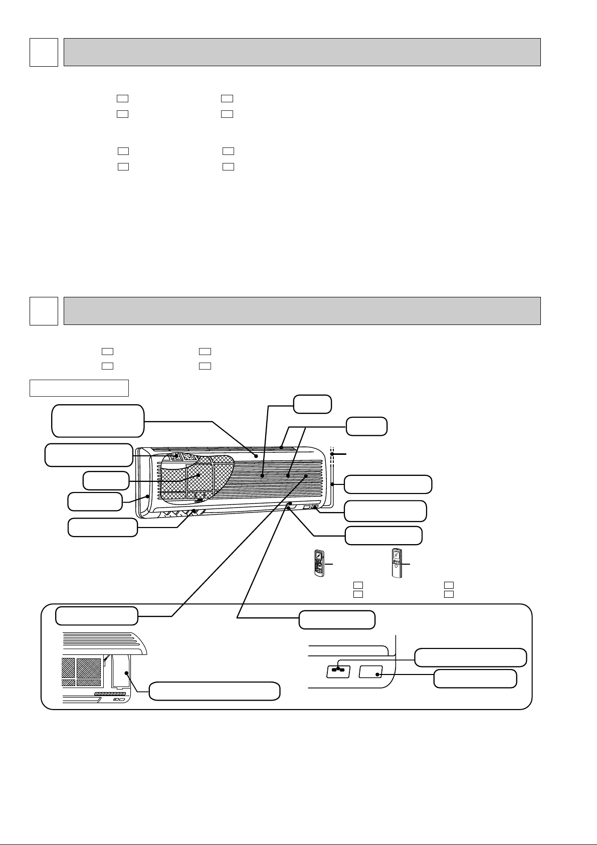
1
Emergency operation switch
Display section
Operation Indicator lamp
Receiving section
Grille
Air cleaning
filter(white bellows
type)
Deodorizing filter
(gray sponge type)
Air filter
Vertical vane
Air inlet
to Breaker
Remote control
receiving section
Horizontal vane
Remote
controller
Remote
controller
MSZ-G09SV MSZ-G12SV -
Operation section
(When the grille is open)
Power supply cord
Front panel
E1
E1
MSZ-G09SV MSZ-G12SV -
E2
E2
TECHNICAL CHANGES
MSZ-G09SV - ➔MSZ-G09SV -
MSZ-G12SV - ➔MSZ-G12SV -
1. Remote controller has been changed.
MUZ-G09SV - ➔MUZ-G09SV MUZ-G12SV - ➔MUZ-G12SV -
1. Only model name has changed.
2
MSZ-G09SVMSZ-G09SV-
PART NAMES AND FUNCTIONS
E1
MSZ-G12SV-
E2
MSZ-G12SV-
E2E1
E2E1
E2E1
E2E1
E1
E2
INDOOR UNIT
2
Signal transmitting section
Operation display section
OPERATE /STOP
(ON /OFF)button
OPERATION SELECT button
FAN SPEED CONTROL button
ON-TIMER button
CLOCK SET button
HR. button
MIN. button
(TIME SET button)
TEMPERATURE buttons
VANE CONTROL button
OFF-TIMER button
RESET button
ON/OFF TOO
WARM
TOO
COOL
HR. MIN.
CLOCK
RESET
CLOCK
MODE
FAN
VANE
START
STOP
ECONO COOL button
ECONO COOL
I FEEL
COOL DRY HEAT
6 00 1
1 00
AM
PM
SWING
SWING button
MUZ-G09SV-
Installation plate
Installation plate fixing screw 4 x 25 mm
Remote controller mounting hardware
Fixing screw for 3 3.5 x 16 mm (Black)
Battery (AAA) for remote controller
Wireless remote controller
Felt tape (Used for left or left-rear piping)
1
5
1
2
2
1
1
1
2
3
4
5
6
7
MUZ-G09SV-
E1
MUZ-G12SV-
E2
MUZ-G12SV-
E1
E2
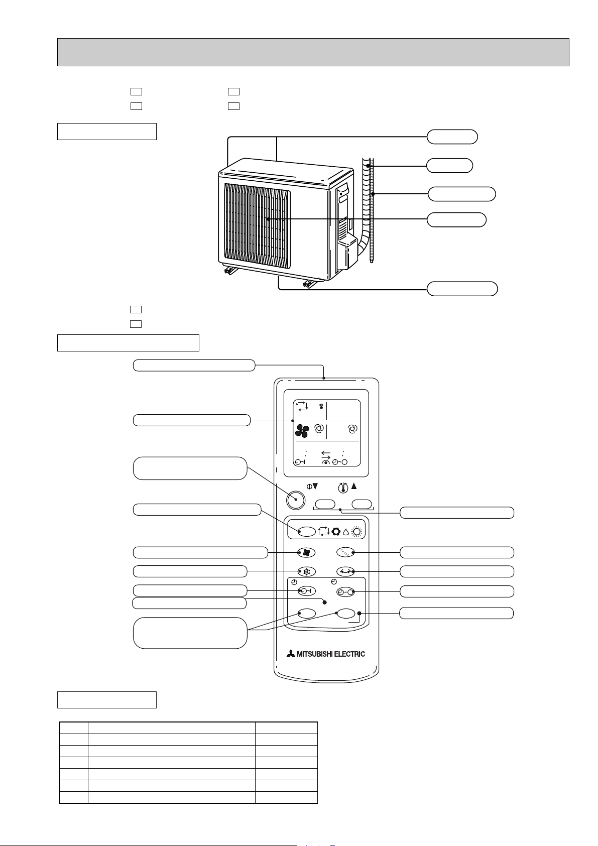
OUTDOOR UNIT
MSZ-G09SVMSZ-G12SV-
E1
E1
REMOTE CONTROLLER
Air inlet
Piping
Drain hose
Air outlet
Drain outlet
ACCESSORIES
Check the following parts before installation.
3
ON/OFF
TOO
COOL
AMPM
AMPM
CLOCK
TOO
WARM
ON/OFF
FAN
TOO
WARM
TOO
COOL
VANE
MODE
ECONO COOL
STOP
START
HR.
MIN.
SWING
I FEEL
COOL
HEAT
DRY
PM
CLOCK
AMPM
RESET CLOCK
:
:
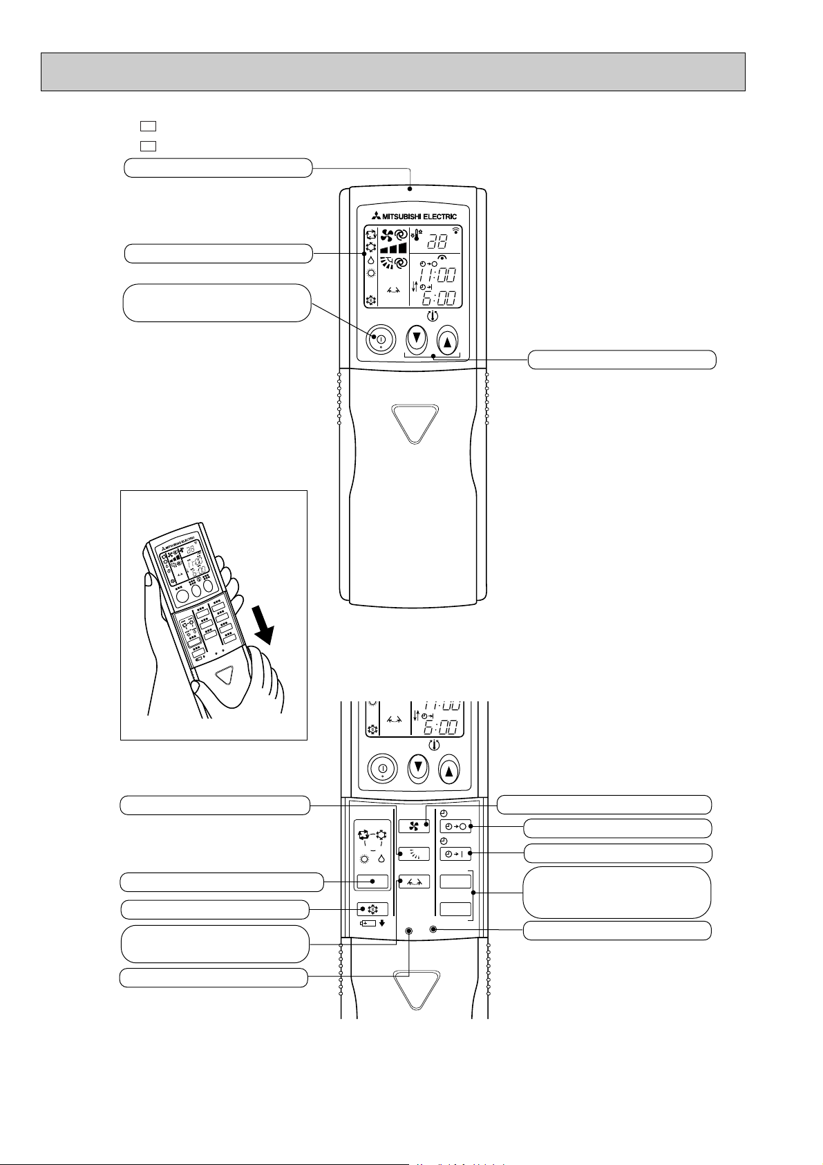
Open the front lid.
Signal transmitting section
Operation display section
OPERATE /STOP
(ON /OFF)button
TEMPERATURE buttons
OPERATION SELECT button
FAN SPEED CONTROL button
OFF-TIMER button
HR. button
MIN. button
(TIME SET button)
ON-TIMER button
RESET button
ECONO COOL button
VANE control button
CLOCK SET button
Vertical vane
swing button
MSZ-G09SVMSZ-G12SV-
E2
E2
4
3
Indoor model
Function
Power supply
Capacity
Air flow(High)
Dehumidification
Power outlet
Running current
Power input
Auxiliary heater
Power factor
Starting current
Fan motor current
Model
Winding
resistance(at20:)
Dimensions WOHOD
Weight
Air direction
Sound level (High)
Fan speed (High)
Fan speed regulator
RT11(at25:)
Thermistor RT12(at25:)
RT13(at25:)
Outdoor model
Outdoor air flow
Compressor motor current
Fan motor current
Model
Output
Winding
resistance(at20:)
Model
Winding
resistance(at20:)
Dimensions WOHOD
Weight
Sound level
Fan speed
Fan speed regulator
Refrigerant filling
capacity(R22)
Refrigerating oil (Model)
RT61(at0:)
Thermistor RT62(at100:)
RT64(at70:)
kW
K /h
R/h
A
A
W
A(kW)
%
A
A
"
mm
kg
dB(A)
rpm
k"
k"
k"
K /h
A
A
W
"
"
mm
kg
dB(A)
rpm
kg
cc
k"
k"
k"
Single phase
230V,50Hz
10
—
90
5.50
0.17
RC4V19-BA
WHT-BLK 292
BLK-RED 325
850O278O191
9
5
3
10
10
10
MUZ-G09SV -
E1
MUZ-G09SV -
E2
1500
0.25
KHV-104FGK
900
U-V 2.14 U-W 2.14
V-W 2.14
RA6V18-AA
WHT-BLK 279
BLK-RED 198
710(+69)o540o255
28
45
600
1
0.75
270 (MS56)
33.2
13.4
7.9
Cooling
2.6 (1.3-3.1)
474
1.2
4.54
940 (440 - 1120)
36
950
4.12
2.77
Heating
3.6 (1.4-5.1)
504
—
5.50
1140 (430 - 1300)
35
1000
5.08
3.16
Electrical
data
Fan
motor
Special
remarks
Compressor
Electrical
data
Fan
motor
Special
remarks
Coefficient of performance(C.O.P)
Capacity
Capacity
MSZ-G09SV -
E1
MSZ-G09SV -
E2
MSZ-G12SV -
E1
MSZ-G12SV -
E2
Single phase
230V,50Hz
10
—
90
7.40
0.19
RC4V19-BA
WHT-BLK 292
BLK-RED 325
850O278O191
10
5
39
3
10
10
10
MUZ-G12SV -
E1
MUZ-G12SV -
E2
1560
0.34
SHV-130FEA
1100
U-V 0.45 U-W 0.45
V-W 0.45
RA6V28-DA
WHT-BLK 201
BLK-RED 350
710(+69)o540o255
34
48
720
1
1.10
350 (MS56)
33.2
13.4
7.9
Cooling
3.5 (0.9-4.0)
588
1.6
6.20
1290 (290 - 1390)
1020
5.67
2.71
Heating
4.8 (0.9-6.7)
642
—
7.40
1540 (290 - 2090)
1100
6.87
3.12
SPECIFICATION
NOTE : Test conditions are based on ISO 5151 (Refrigerant piping length (one way): 5m)
Cooling : Indoor DB27: WB19:
Heating : Indoor DB 20: WB15:
Outdoor DB35: WB(24:)
Outdoor DB 7: WB 6:
5
1.5+ 440V
250V 3.15A
93:5A 250V
MP20GA 12V 300"
ERZV10D471
S201DH1Y
5P
JM1aN-ZTMP-DC12V
136:i3: 2A
100+ 420V
1500+ 420V
8A 8mH
70m" 5W
10" 15W
EM43261
QM15TG-9B
INDOOR UNIT
OUTDOOR UNIT
Item
Model
Model
Item
Indoor fan capacitor
Fuse
Thermal fuse
Vane motor
Varistor
Solid state relay
Terminal block
Contactor
Indoor fan motor thermal fuse
Current transformer
Power-facrtor capacitor
Smoothing capacitor
Outdoor fan capacitor
Diode stack
Fuse
Fuse
Expansion valve coil
Reactor
Current-detecting resistor
Current-limiting resistor
Solid state relay
Terminal block
Outdoor fan relay
Current-limiting relay
R.V. coil
Noise filter
Transistor module
MSZ-G09SV -
E1
MSZ-G12SV -
E1
MUZ-G12SV -
E1
MSZ-G09SV -
E2
MSZ-G12SV -
E2
165+ 420V
2500+ 420V
15A 4.3mH
100m" 5W
10" 20W
EM43262
QM20TG-9B
MUZ-G09SV -
E1
MUZ-G12SV -
E2
MUZ-G09SV -
E2
RR-18
1.8+ 440V
S25VB80
250V 2A
250V 1A
LAM-MD12ME 12VDC
TLP3506
4P
G5S-1
G4A-1A
LB8 220-240V AC
(CT61)
(C61)
(C63)
(C65)
(DS61, DS62)
(F801)
(F901)
(LEV)
(L61)
(R61, R62)
(R64)
(SSR61)
(TB2)
(X61)
(X64)
(21S4)
(C11)
(F11)
(F12)
(MV1, MV2)
(NR11)
(SR141)
(TB)
(52C)
Specifications and rating conditions of main electric parts
6

4
90
80
70
60
50
40
30
20
10
63 125 250 500 1000 2000 4000 8000
NC-60
NC-50
NC-40
NC-30
NC-20
NC-70
OCTAVE BAND SOUND PRESSURE LEVEL, dB re 0.002 MICRO BAR
BAND CENTER FREQUENCIES, Hz
Test conditions,
Cooling : DB 27: WB 19:
APPROXIMATE
THRESHOLD OF
HEARING FOR
CONTINUOUS
NOISE
COOLING
FUNCTION
36
SPL(dB(A)) LINE
High
SPEED
HEATING
Heating : DB 20: WB 15:
90
80
70
60
50
40
30
20
10
63 125 250 500 1000 2000 4000 8000
NC-60
NC-50
NC-40
NC-30
NC-20
NC-70
OCTAVE BAND SOUND PRESSURE LEVEL, dB re 0.002 MICRO BAR
BAND CENTER FREQUENCIES, Hz
Test conditions,
Cooling : DB 35: WB (24:)
APPROXIMATE
THRESHOLD OF
HEARING FOR
CONTINUOUS
NOISE
COOLING
FUNCTION
45
SPL(dB(A)) LINE
High
SPEED
HEATING
Heating : DB 7: WB 6:
NOISE CRITERIA CURVES
MSZ-G09SVMSZ-G09SV-
E1
E2
MUZ-G09SVMUZ-G09SV-
E1
E2
MSZ-G12SVMSZ-G12SV-
90
80
70
60
50
40
30
APPROXIMATE
20
THRESHOLD OF
HEARING FOR
OCTAVE BAND SOUND PRESSURE LEVEL, dB re 0.002 MICRO BAR
CONTINUOUS
NOISE
10
E1
E2
SPEED
High
FUNCTION
COOLING
HEATING
Test conditions,
Cooling : DB 27: WB 19:
Heating : DB 20: WB 15:
63 125 250 500 1000 2000 4000 8000
BAND CENTER FREQUENCIES, Hz
SPL(dB(A)) LINE
39
MUZ-G12SVMUZ-G12SV-
NC-70
NC-60
NC-50
NC-40
NC-30
NC-20
OCTAVE BAND SOUND PRESSURE LEVEL, dB re 0.002 MICRO BAR
7
E1
E2
SPEED
High
FUNCTION
COOLING
HEATING
SPL(dB(A)) LINE
Test conditions,
Cooling : DB 35: WB (24:)
Heating : DB 7: WB 6:
90
80
70
60
50
40
30
APPROXIMATE
20
THRESHOLD OF
HEARING FOR
CONTINUOUS
NOISE
10
63 125 250 500 1000 2000 4000 8000
BAND CENTER FREQUENCIES, Hz
48
NC-70
NC-60
NC-50
NC-40
NC-30
NC-20
5
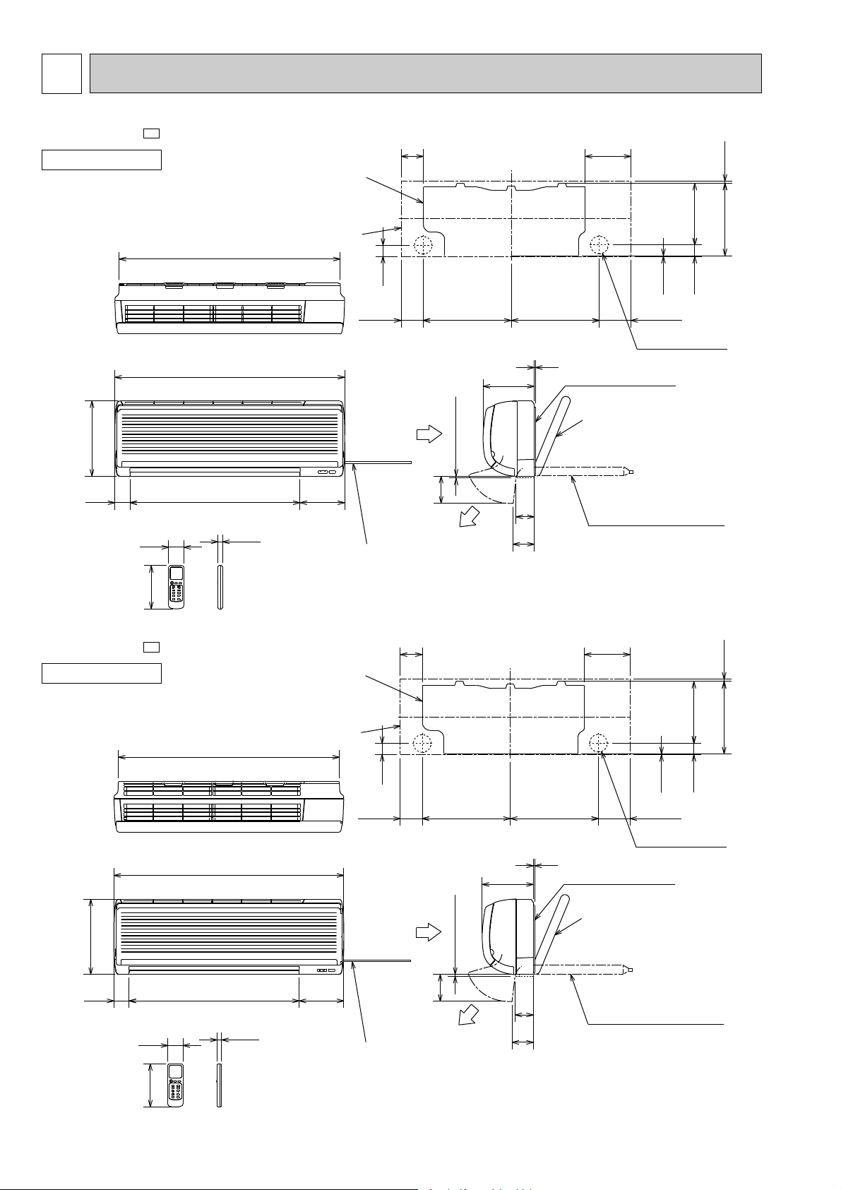
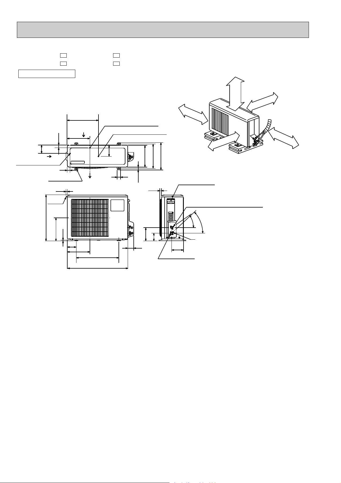
OUTLINES AND DIMENSIONS
MSZ-G09SV-
INDOOR UNIT
Unit: mm
E1
82 169
Installation plate
271 4.5
Indoor unit
818
231.5
278
Wireless remote controller
MSZ-G12SV-
INDOOR UNIT
56
160
E1
850
17.5
16562956
Power supply cord
Lead to right 1.0m
Lead to left 0.3m
Installation plate
41
Air in
82
326 326
189
7 or more
100
Air out
67
78
5
Installation plate
Liquid line [6.35-0.5m
Gas line [9.52-0.43m
{
Insulation [37 O.D.
Drain hose [16
(Connected part O.D.)
Insulation [28
169
42
2.5
116.581.5
Wall hole [65
[21 I.D.
278
56
160
Wireless remote controller
818
850
17.5
Indoor unit
16562956
Power supply cord
Lead to right 1.0m
Lead to left 0.3m
41
Air in
326 326
189
or more
7
100
Air out
67
78
5
Installation plate
Liquid line [6.35-0.5m
Gas line [9.52-0.43m
{
Insulation [37 O.D.
Drain hose [16
(Connected part O.D.)
Insulation [28
231.5
42
2.5
116.581.5
Wall hole [65
[21 I.D.
271 4.5
8
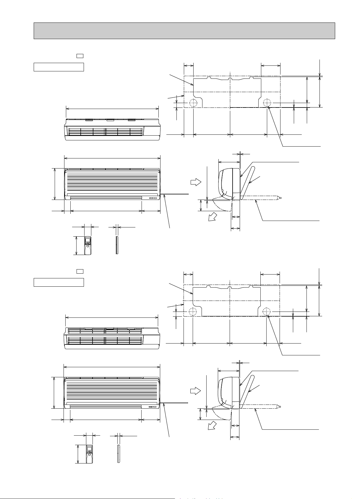
MSZ-G09SV-
INDOOR UNIT
Unit: mm
E2
82 169
Installation plate
271 4.5
Indoor unit
818
231.5
278
58
162
Wireless remote controller
MSZ-G12SV-
INDOOR UNIT
41
326 326
67
78
5
Installation plate
Liquid line [6.35-0.5m
Gas line [9.52-0.43m
{
Insulation [37 O.D.
Drain hose [16
(Connected part O.D.)
Insulation [28
169
850
Air in
7 or more
16562956
19
Power supply cord
Lead to right 1.0m
Lead to left 0.3m
E2
Installation plate
100
Air out
82
189
116.581.5
Wall hole [65
42
2.5
[21 I.D.
278
818
850
58
162
Wireless remote controller
19
Indoor unit
16562956
Power supply cord
Lead to right 1.0m
Lead to left 0.3m
41
Air in
271 4.5
231.5
42
2.5
326 326
5
189
or more
7
100
Air out
9
67
78
Installation plate
Liquid line [6.35-0.5m
Gas line [9.52-0.43m
{
Insulation [37 O.D.
Drain hose [16
(Connected part O.D.)
Insulation [28
116.581.5
Wall hole [65
[21 I.D.
Liquid refrigerant pipe joint
Refrigerant pipe (flared) [6.35
Service panel
Gas refrigerant pipe joint
Refrigerant pipe (flared)
[9.52 (MUZ-G09SV
)
Service port
Bolt pitch for installation
Handle
Air out
Air in
Drainage holes [28
4 holes 10o21
18
500
710
265
105
69
138
20
40
However, either the
left/ right sides or
back side should
be unobstructed.
Air in
265
REQUIRED SPACE
Even if the right/ left sides or
back side are vacant, the top
has to be at least 100mm
unobstructed.
Drainage holes [28
127
32.4
92
367
Drainage holes [28
33
32.5
255
285
320
155
90
43-
35-
540
270
10
350mm or more
100mm or more
100mm or more
100mm or more
Basically
unobstructed
[12.7 (MUZ-G12SV
)
W A
W A
W B
W A In case of poorly-ventilated place, the front or the back
has to be at least 200 mm unobstructed.
W B The wall may get dirty in case the air is discharged
toward it.
MUZ-G09SV- MUZ-G12SVMUZ-G09SV- MUZ-G12SV-
OUTDOOR UNIT
E1E1
E2E2
Unit: mm
10
6 WIRING DIAGRAM
POWER
SUPPLY
CORD
~/N 230V
50Hz
GRN/YLW
BLK
GRY
YLW
BRN
WHT
RED
MF
1
2
3
4
5
6
3
SR141
3
2
1
CN
121
C11
HIC1
TRANS
MV2
RT13
4
3
2
1
CN112
151
CN
MV1
10
RT12
RT11
111
CN
CN211
NR11
ELECTRONIC CONTROL P.C. BOARD
F11
230V~
BRN
TB
L
3
2
N
BLU
BRN
WHT
BLU
F12
RED
BLU
BLU
1
2
BLU
1
2
3
CN201
3
4
52C
PE
CIRCUIT BREAKER
12V
TO OUTDOOR
UNIT
CONNECTING
REMOTE
CONTROLLER
POWER MONITOR,
RECEIVER
P.C. BOARD
5
LD101T
SYMBOL
C11
F11
F12
HIC1
MF
SYMBOL
MV1
MV2
NR11
RT11
RT12
SYMBOL
RT13
SR141
TB
52C
NAME
INDOOR FAN CAPACITOR
FUSE (3.15A)
THERMAL FUSE (93:)
DC/DC CONVERTER
INDOOR FAN MOTOR(INNER FUSE)
NAME
VANE MOTOR (HORIZONTAL)
VANE MOTOR (VERTICAL)
VARISTOR
ROOM TEMPERATURE THERMISTOR
INDOOR COIL THERMISTOR (MAIN)
NAME
INDOOR COIL THERMISTOR (SUB)
SOLID STATE RELAY
TERMINAL BLOCK
CONTACTOR
GRN/YLW
GRN/YLW
LD101T
5
POWER MONITOR,
RECEIVER
P.C.BOARD
REMOTE
CONTROLLER
TO OUTDOOR
UNIT
CONNECTING
12V
CIRCUIT BREAKER
PE
52C
4
3
CN201
3
2
1
BLU
2
1
BLU
BLU
RED
F12
BLU
WHT
BRN
BLU
N
2
3
L
TB
BRN
230V~
F11
ELECTRONIC CONTROL P.C. BOARD
NR11
CN211
CN
111
RT11
RT12
10
MV1
CN
151
CN112
1
2
3
4
RT13
MV2
TRANS
HIC1
C11
121
CN
1
2
3
SR141
3
6
5
4
3
2
1
MF
RED
WHT
BRN
YLW
GRY
BLK
GRN/YLW
POWER
SUPPLY
CORD
~/N 230V
50Hz
SYMBOL
C11
F11
F12
HIC1
MF
SYMBOL
MV1
MV2
NR11
RT11
RT12
SYMBOL
RT13
SR141
TB
52C
NAME
INDOOR FAN CAPACITOR
FUSE (3.15A)
THERMAL FUSE (93:)
DC/DC CONVERTER
INDOOR FAN MOTOR(INNER FUSE)
NAME
VANE MOTOR (HORIZONTAL)
VANE MOTOR (VERTICAL)
VARISTOR
ROOM TEMPERATURE THERMISTOR
INDOOR COIL THERMISTOR (MAIN)
NAME
INDOOR COIL THERMISTOR (SUB)
SOLID STATE RELAY
TERMINAL BLOCK
CONTACTOR
MSZ-G09SVMSZ-G12SV-
INDOOR UNIT
E1
E1
MODELS WIRING DIAGRAM
NOTE:1. About the outdoor side electric wiring refer to the outdoor unit electric wiring diagram for servicing.
2. Use copper conductors only. (For field wiring)
3. Symbols below indicate.
/: Terminal block, : Connector
E2
E2
MODELS WIRING DIAGRAM
11
MSZ-G09SVMSZ-G12SV-
NOTE:1. About the outdoor side electric wiring refer to the outdoor unit electric wiring diagram for servicing.
2. Use copper conductors only. (For field wiring)
3. Symbols below indicate.
/: Terminal block, : Connector
SG79B727H01
SG79J166H01
MUZ-G09SVMUZ-G09SV-
E1
E2
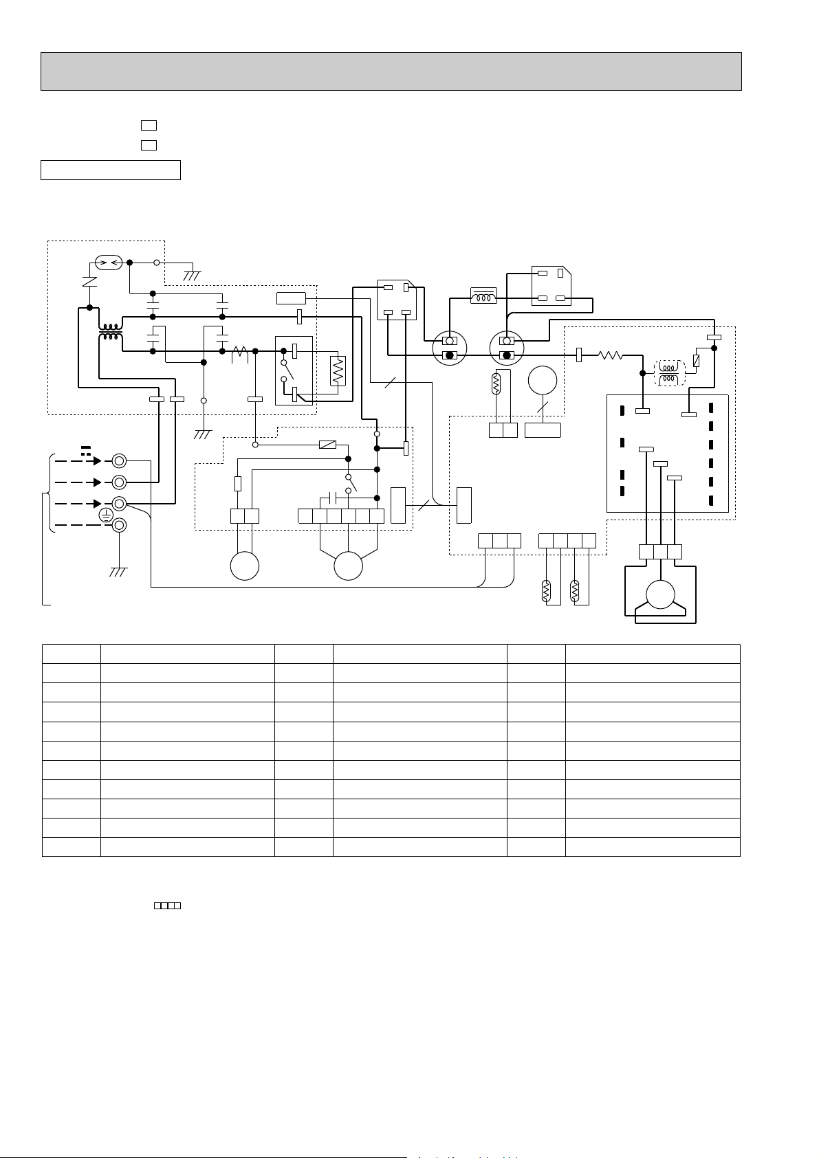
OUTDOOR UNIT
MODELS WIRING DIAGRAM
DSA61
NR61
NOISE FILTER
P.C. BOARD
12V
230V ~
GRN/YLW
FROM INDOOR UNIT
CONNECTING
L62
3
2
N
TB2
LDE2
TAB66
RED
WHT
BLU
CY61
CY62
GRN
LDE1
TAB65
GRN
CN721
21S4: heating ON
CY63
CT61
CY64
LD64
SSR61
21S4 MF61
CN725
TAB69
X64
TAB68
BLU
RELAY
P.C. BOARD
CN771
12
3
4
6 5 4 3 2 1
WHT
BLU
ORN
F901
C65
RED
R64
ORN
LD62
BLK
X61
DS61
(
(-)
4
WHT
~
)
+)
(
(
~
WHT
TAB
67
CN723
BLK
)
YLW
DS62
RED
(~)
+)
(
(-)
(~)
BLK
+
YLW
-
RED
TAB64
R61
RED
TAB63
T801
F801
LEV
BUN
BVN
N
U
P
BUP
TR
V
EUPEVP
BVP
6
CN724
2
+
-
C61
BLK
L61
C63
YLW
RED
RT64
1
CN642
W
3
ELECTRONIC
CONTROL
P.C. BOARD
CN722
CN601
2
1
3
BLU
RED
1
RT61
CN641
2
3
RT62
BWN
EUN
RED
WHT
4
BLK
1
WHT
W
2
MC
3
V
U
BWP
EWP
REDBLK
SYMBOL
CT61
C61
C63
C65
CY61~64
DSA61
DS61,62
F801
F901
LEV
NOTE:1. About the indoor side electric wiring refer to the indoor unit electric wiring diagram for servicing.
CURRENT TRANSFORMER
POWER-FACTOR CAPACITOR
SMOOTHING CAPACITOR
OUTDOOR FAN CAPACITOR
CAPACITOR
SURGE ABSORBER
DIODE STACK
FUSE (2A)
FUSE (1A)
EXPANSION VALVE COIL
2.Use copper conductors only. (For field wiring)
3. Symbols below indicate.
/: Terminal block, : Connector
NAME
SYMBOL
L61
L62
MC
MF61
NR61
RT61
RT62
RT64
R61
R64
NAME
REACTOR
CMC COIL
COMPRESSOR
OUTDOOR FAN MOTOR(INNER PROTECTOR)
VARISTOR
DEFROST THERMISTOR
DISCHARGE TEMPERATURE THERMISTOR
FIN TEMPERATURE THERMISTOR
CURRENT-DETECTING RESISTOR
CURRENT-LIMITING RESISTOR
SYMBOL
SSR61
TB2
TR
T801
X61
X64
21S4
NAME
SOLID STATE RELAY
TERMINAL BLOCK
POWER TRANSISTOR MODULE
TRANSFORMER
OUTDOOR FAN RELAY
CURRENT-LIMITING RELAY
R.V. COIL
SG79B710H03
12
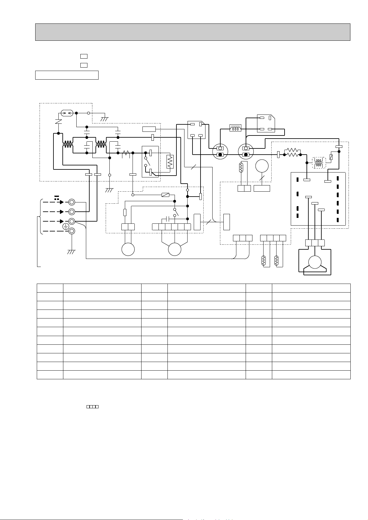
MUZ-G12SVMUZ-G12SV-
E1
E2
OUTDOOR UNIT
MODELS WIRING DIAGRAM
DSA61
NR61
L62
NOISE FILTER
P.C. BOARD
12V
230V ~
GRN/YLW
FROM INDOOR UNIT
CONNECTING
N
3
2
TB2
TAB66
RED
WHT
BLU
LDE2
CY61
CY62
GRN
L63
TAB65
CN721
CN725
CY63
CY64
LDE1
GRN
21S4: heating ON
TAB69
CT61
X64
TAB68
BLU
LD64
RELAY
SSR61
P.C BOARD
12
CN771
21S4 MF61
ORN
WHT
3
BLU
R64
4
ORN
LD62
F901
C65
X61
6 5 4 3 2 1
BLK
RED
DS61
(
~
(
4
WHT
-
)
)
TAB
67
+)
(
(
)
~
YLW
WHT
CN723
BLK
3
+
-
C61
BLK
L61
C63
YLW
CN722
DS62
RED
(~)
(-)
BLK
RED
+
YLW
-
RT64
CN642
LEV
6
1
CN724
2
ELECTRONIC
CONTROL
P.C. BOARD
CN601
1
2
3
BLU
1
RED
RT61
+)
(
(~)
TAB64
CN641
2
RED
3
RT62
RED
R62
R61
N
BUN
BVN
BWN
EUN
4
BLK
W
U
BLK
1
WHT
T801
V
WHT
2
MC
TR
V
TAB63
W
RED
3
U
P
RED
F801
BUP
EUPEVP
BVP
BWP
EWP
SYMBOL
CT61
C61
C63
C65
CY61~64
DSA61
DS61,62
F801
F901
LEV
NOTE:1. About the indoor side electric wiring refer to the indoor unit electric wiring diagram for servicing.
CURRENT TRANSFORMER
POWER-FACTOR CAPACITOR
SMOOTHING CAPACITOR
OUTDOOR FAN CAPACITOR
CAPACITOR
SURGE ABSORBER
DIODE STACK
FUSE (2A)
FUSE (1A)
EXPANSION VALVE COIL
2.Use copper conductors only. (For field wiring)
3. Symbols below indicate.
/: Terminal block, : Connector
NAME
SYMBOL
L61
L62, 63
MC
MF61
NR61
RT61
RT62
RT64
R61, 62
R64
NAME
REACTOR
CMC COIL
COMPRESSOR
OUTDOOR FAN MOTOR(INNER PROTECTOR)
VARISTOR
DEFROST THERMISTOR
DISCHARGE TEMPERATURE THERMISTOR
FIN TEMPERATURE THERMISTOR
CURRENT-DETECTING RESISTOR
CURRENT-LIMITING RESISTOR
SYMBOL
SSR61
TB2
TR
T801
X61
X64
21S4
NAME
SOLID STATE RELAY
TERMINAL BLOCK
POWER TRANSISTOR MODULE
TRANSFORMER
OUTDOOR FAN RELAY
CURRENT-LIMITING RELAY
R.V. COIL
SG79B873H03
13
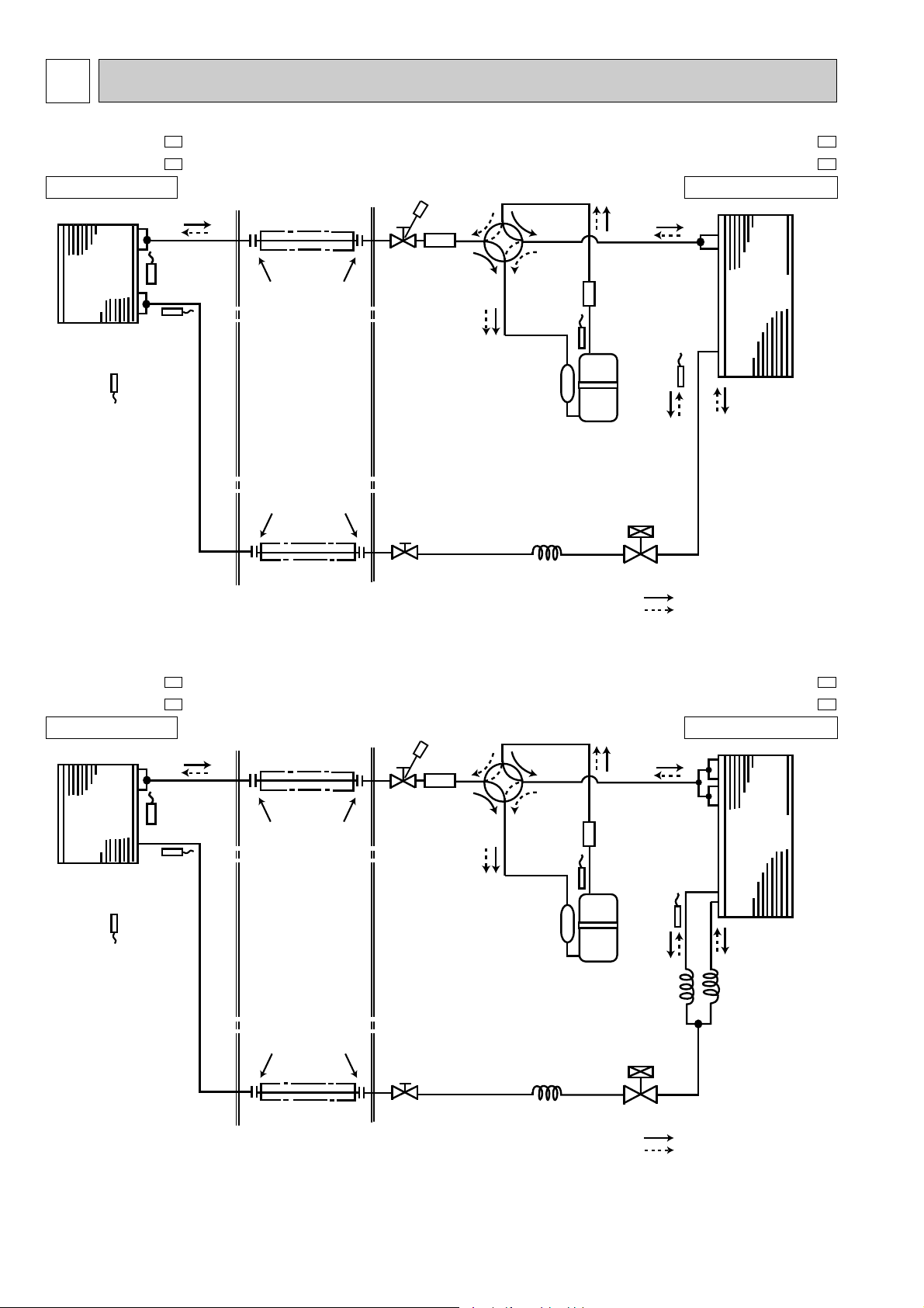
7
Indoor
heat
exchanger
Outdoor
heat
exchanger
Flared connection
Room temperature
thermistor
RT11
Indoor coil
temperature
thermistor
RT13(sub)
Defrost
temperatuer
thermistor
RT61
Discharge
temperatuer
thermistor
RT62
Flared connection
Stop valve
(with strainar)
Stop valve
(with service port)
Capillary tube
[3.0✕[1.8✕400
Refrigerant flow in cooling
Compressor
Accumulator
Muffler
Muffler
4-way valve
Refrigerant flow in heating
Refrigerant pipe [9.52
(with heat insulator)
Refrigerant pipe
[6.35
(with heat insulator)
Indoor coil
temperature
thermistor
RT12(main)
Expansion
valve
R.V. coil
heating ON
cooling OFF
Indoor
heat
exchanger
Outdoor
heat
exchanger
Flared connection
Room temperature
thermistor
RT11
Indoor coil
temperatuer
thermistor
RT13(sub)
Defrost
temperature
thermistor
RT61
Discharge
temperature
thermistor
RT62
Flared connection
Stop valve
(with strainar)
Stop valve
(with service port)
Capillary tube
[3.0✕[2.0✕200
Capillary
tube
[3.0✕[2.0✕300
Refrigerant flow in cooling
Compressor
Accumulator
Muffler
Muffler
4-way valve
Refrigerant flow in heating
Refrigerant pipe [12.7
(with heat insulator)
Refrigerant pipe
[6.35
(with heat insulator)
Capillary
tube
[3.0✕[2.0✕300
Indoor coil
temperatuer
thermistor
RT12(main)
Expansion
valve
R.V. coil
heating ON
cooling OFF
REFRIGERANT SYSTEM DIAGRAM
MSZ-G09SV MSZ-G09SV -
INDOOR UNIT
Unit : mm
E1
E2
MUZ-G09SV MUZ-G09SV -
E1
E2
OUTDOOR UNIT
MSZ-G12SV MSZ-G12SV -
INDOOR UNIT
E1
E2
Unit : mm
MUZ-G12SV MUZ-G12SV -
OUTDOOR UNIT
E1
E2
14
MAX. REFRIGERANT PIPING LENGTH
Refrigerant Piping
Max. length
A
w Height difference should be within
8m(MSZ-G09SV)/ 10m(MSZ-G12SV)
regardless of which unit,
indoor or outdoor position is high.
w Max. Height
difference 8m
(MSZ-G09SV
)
Indoor
unit
Outdoor unit
w Max. Height
difference 10m
(MSZ-G12SV
)
Refrigerant piping
Max. length : m
A
12
15
Indoor unit
Gas 0.43
Liquid 0.5
Gas
9.52
12.7
Liquid
6.35
Outdoor unit
Piping size O.D : mm Length of connecting pipe : m
Model
MSZ-G09SV -
E1
MUZ-G09SV -
E1
MSZ-G09SV -
E2
MUZ-G09SV -
E2
MSZ-G12SV -
E1
MUZ-G12SV -
E1
MSZ-G12SV -
E2
MUZ-G12SV -
E2
Outdoor unit
precharged
750
1100
14m
270
7m
60
60
6m
30
30
5m
0
0
11m
180
180
Model
Refrigerant piping length (one way)
Calculation : Xg=30g/mo(Refrigerant piping length(m) - 5)
8m
90
90
9m
120
120
10m
150
150
12m
210
210
13m
240
15m
300
MSZ-G09SV -
E1
MUZ-G09SV -
E1
MSZ-G09SV -
E2
MUZ-G09SV -
E2
MSZ-G12SV -
E1
MUZ-G12SV -
E1
MSZ-G12SV -
E2
MUZ-G12SV -
E2
MAX. HEIGHT DIFFERENCE
ADDITIONAL REFRIGERANT CHARGE (R22:g)
15
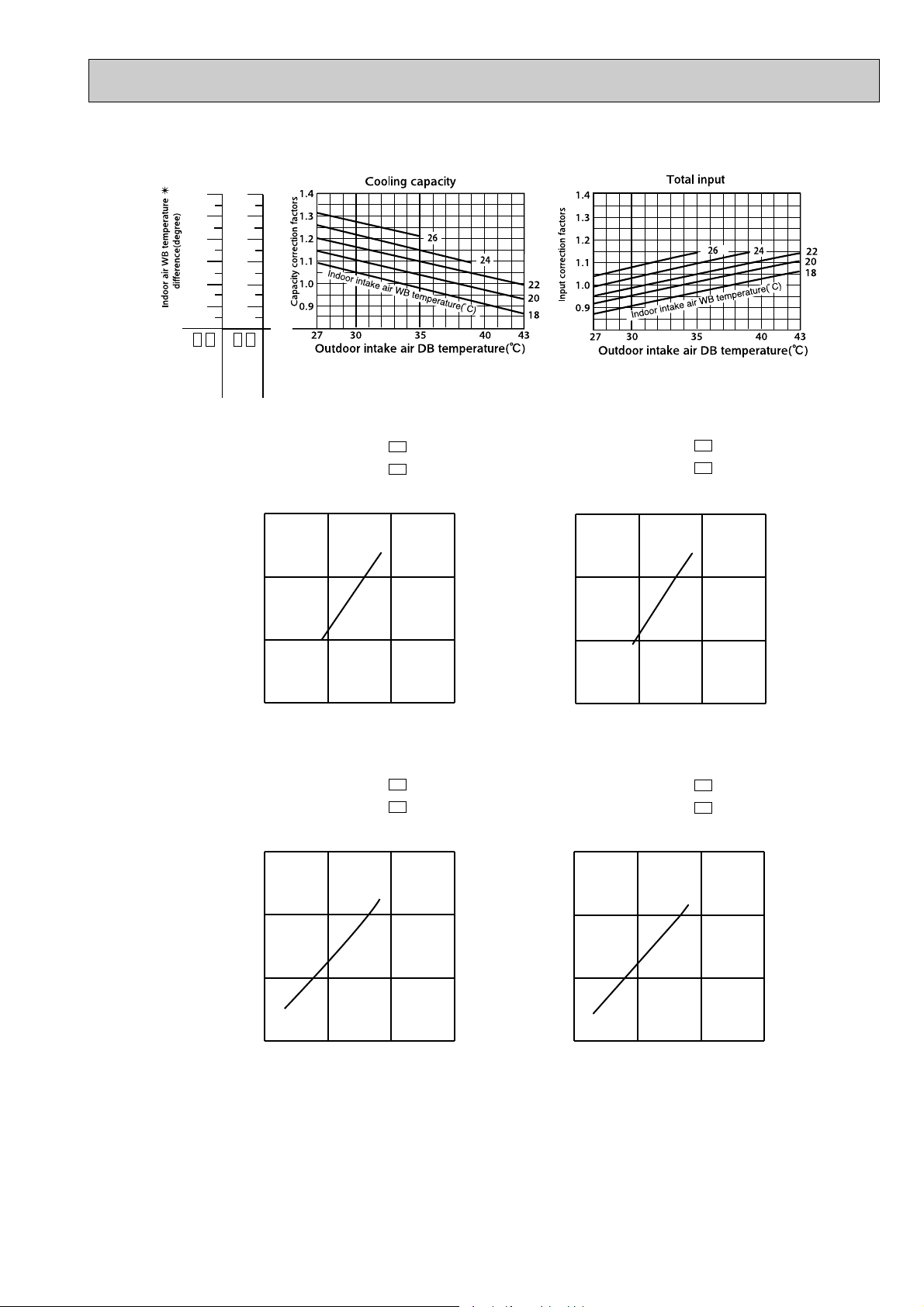
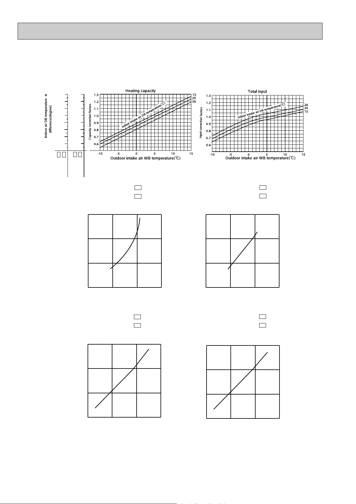
PERFORMANCE CURVES8
MSZ-G09SVMUZ-G09SV-
The standard data contained in these specifications apply only to the operation of the air conditioner under normal conditions.
Since operating conditions vary according to the areas where these units are installed. The following information has been
provided to clarify the operating characteristics of the air conditioner under the conditions indicated by the performance curve.
(1) GUARANTEED VOLTAGE
207 ~ 253V, 50Hz
(2) AIR FLOW
Air flow should be set at MAX.
(3) MAIN READINGS
(1) Indoor intake air wet-bulb temperature ::WB
(2) Indoor outlet air wet-bulb temperature ::WB
(3) Outdoor intake air dry-bulb temperature ::DB
(4) Total input :W
(5) Indoor intake air dry-bulb temperature ::DB
(6) Outdoor intake air wet-bulb temperature ::WB
(7) Total input :W
Indoor air wet/dry-bulb temperature difference on the left side of the chart on page 15 and 16 shows the difference
between the indoor intake air wet/dry-bulb temperature and the indoor outlet air wet/dry-bulb temperature for your reference at service.
E1
MSZ-G09SV-
E1
MUZ-G09SV-
E2
MSZ-G12SV-
E2
MUZ-G12SV-
Cooling
}
Heating
}
E1
MSZ-G12SV-
E1
MUZ-G12SV-
E2
E2
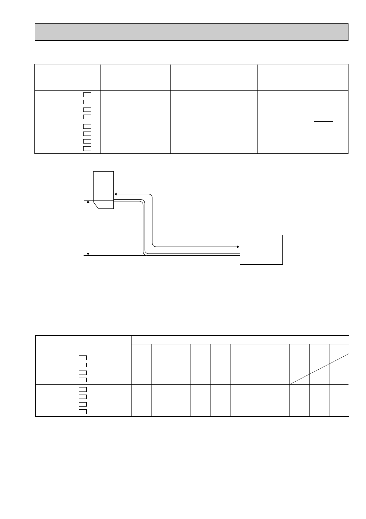
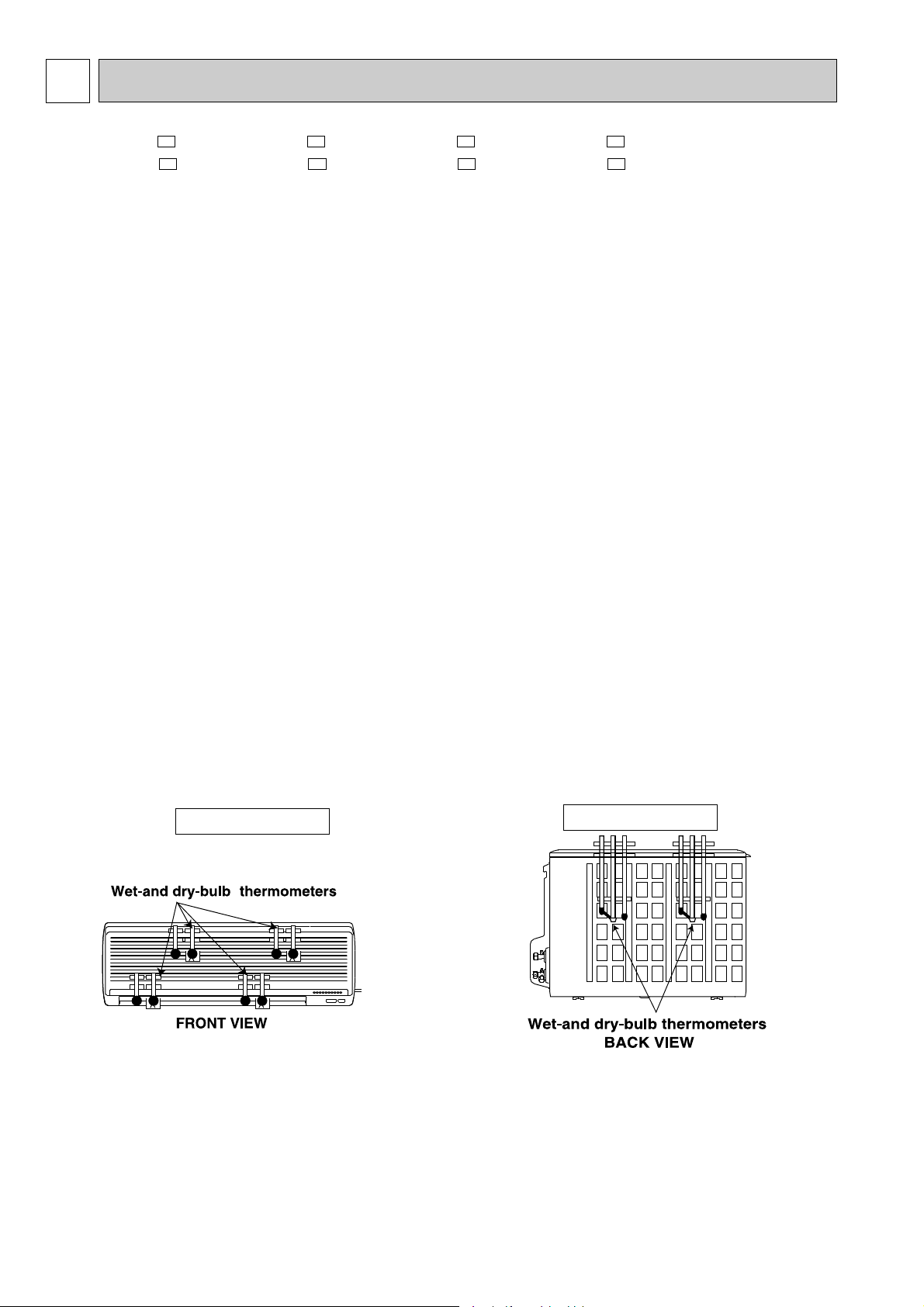
How to measure the indoor air wet-bulb/ dry-bulb temperature difference
1. Attach at least 2 sets of wet-and dry-bulb thermometers to the indoor air intake as shown in the figure, and at least 2 sets
of wet-and dry-bulb thermometers to the indoor air outlet. The thermometers must be attached to the position where air
speed is high.
2. Attach at least 2 sets of wet-and dry-bulb thermometers to the outdoor air intake.
Cover the thermometers to prevent direct rays of the sun.
3. Check that the air filter is cleaned.
4. Open windows and doors of room.
5. Press the EMERGENCY OPERATION switch once (twice) to start the EMERGENCY COOL (HEAT) MODE.
6. When system stabilizes after more than 15 minutes, measure temperature and take an average temperature.
7. 10 minutes later, measure temperature again and check that the temperature does not change.
INDOOR UNIT
OUTDOOR UNIT
16
11.5
10.5
9.6
8.6
7.7
6.8
MSZ-G09SV- E1
MSZ-G09SV- E2
11.6
10.6
9.6
8.7
7.8
6.9
MSZ-G12SV- E1
MSZ-G12SV- E2
0 50 100 150(Hz)
0.0
0.5
1.0
1.5
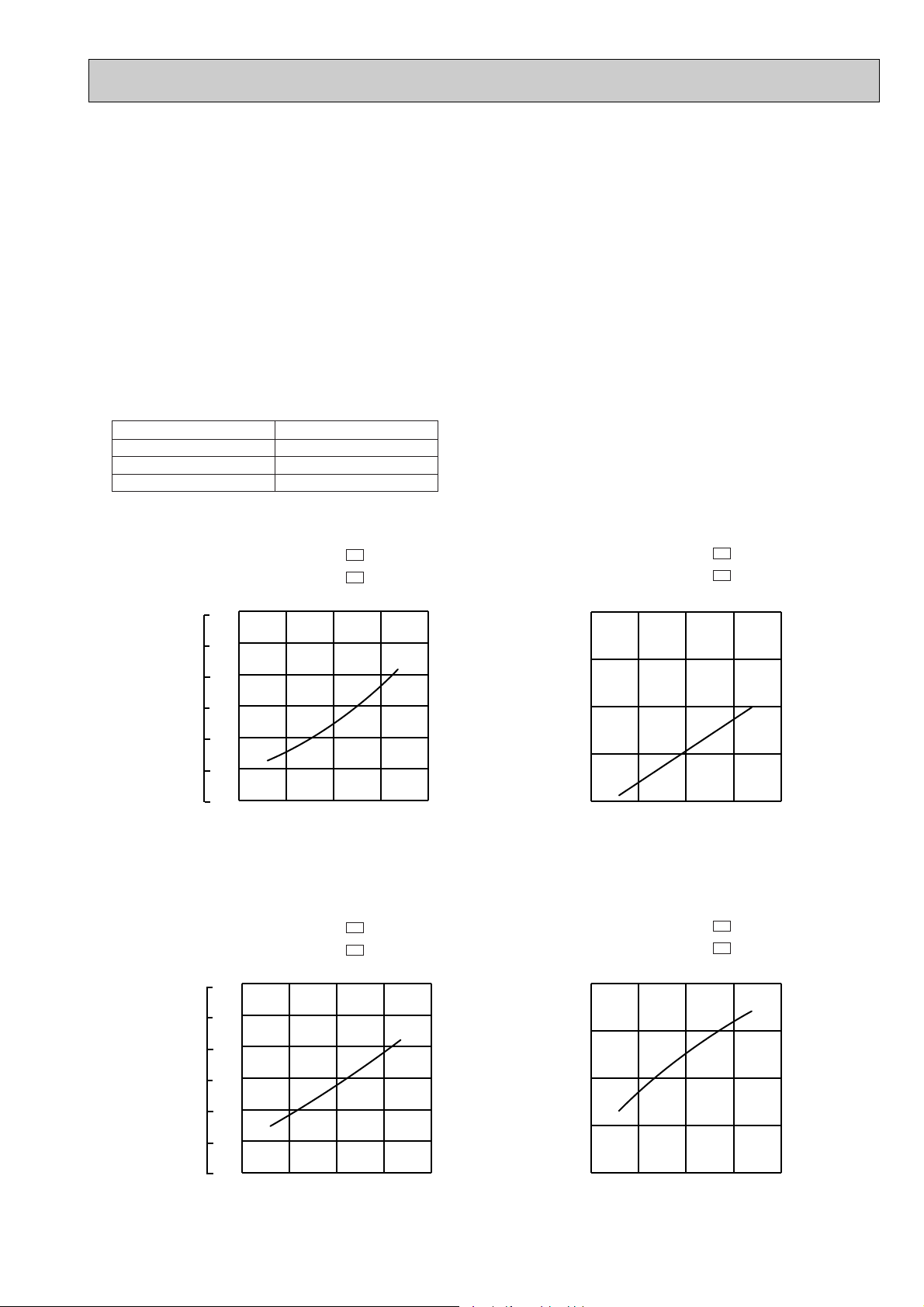
Correction of Cooling capacity
Capacity correction factors
The operational frequency of compressor
Cooling capacity
✴ These values are under rated (frequency).
MUZ-G09SV MUZ-G09SV -
MUZ-G12SV MUZ-G12SV -
E1
E2
E1
E2
Correction of Cooling capacity
1.5
MUZ-G09SV MUZ-G09SV -
E1
E2
Correction of total input
1.5
1.0
0.5
Input correction factors
0.0
0 50 100 150(Hz)
The operational frequency of compressor
MUZ-G12SV MUZ-G12SV -
E1
E2
Correction of total input
1.5
1.0
0.5
Capacity correction factors
0.0
0 50 100 150(Hz)
The operational frequency of compressor
17
1.0
0.5
Input correction factors
0.0
0 50 100 150
The operational frequency of compressor
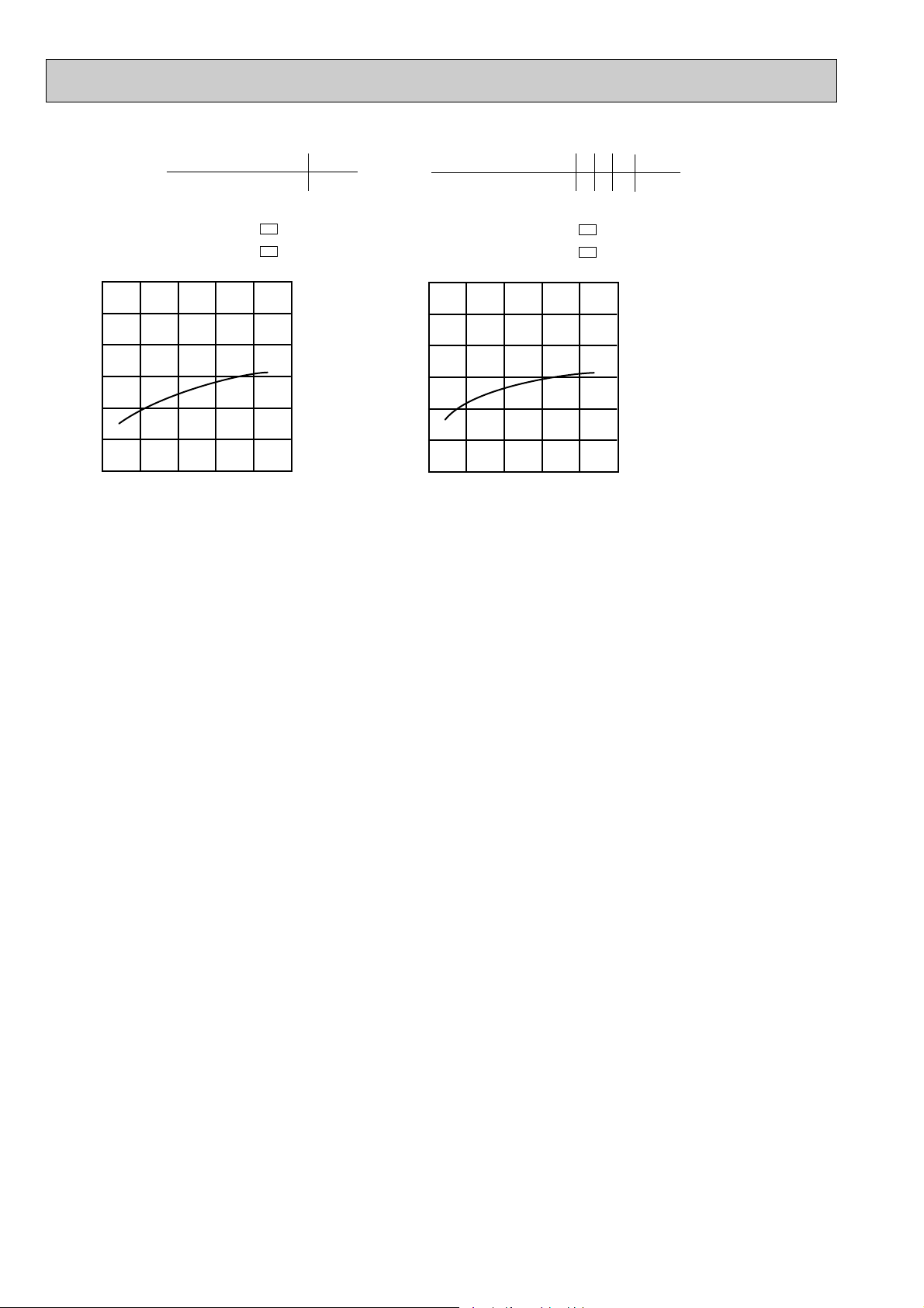
28.0
25.9
23.7
21.6
19.4
17.2
15.1
12.9
MSZ-G09SV- E1
MSZ-G09SV- E2
29.3
27.1
24.8
22.6
20.3
18.1
15.8
13.5
MSZ-G12SV- E1
MSZ-G12SV- E2
Heating capacity
0 50 100 150(Hz)
0.0
0.5
1.0
1.5
Correction of Heating capacity
Capacity correction factors
The operational frequency of compressor
Correction of total input
Input correction factors
The operational frequency of compressor
0 50 100 150(Hz)
0.0
0.5
1.0
1.5
NOTE:The following curves are for the heating operation without any frost.
✴ These values are under rated (frequency).
MUZ-G09SV MUZ-G09SV -
MUZ-G12SV MUZ-G12SV -
E1
E2
E1
E2
Correction of Heating capacity
1.5
MUZ-G09SV MUZ-G09SV -
MUZ-G12SV MUZ-G12SV -
Correction of total input
1.5
E1
E2
E1
E2
Capacity correction factors
1.0
0.5
0.0
0 50 100 150(Hz)
The operational frequency of compressor
18
1.0
0.5
Input correction factors
0.0
0 50 100 150(Hz)
The operational frequency of compressor
OUTDOOR LOW PRESSURE AND OUTDOOR UNIT CURRENT
(MPa [Gauge])
(kgf/F [Gauge])
18 32
15 20
50
25
60
30
70(%)
35(:)
0.2
0.3
0.4
0.5
0.6
0.7
79Hz
2
3
4
5
6
7
8
0.8
15 20
50
25
60
30
70(%)
35(:)
3
4
5
6
7
79Hz
32
18
(MPa [Gauge])
(kgf/F [Gauge])
18 32
15 20
50
25
60
30
70(%)
35(:)
0.2
0.3
0.4
0.5
0.6
0.7
85Hz
2
3
4
5
6
7
8
0.8
15 20
50
25
60
30
70(%)
35(:)
3
4
5
6
7
85Hz
32
18
How to operate with fixed operational frequency of the compressor.
1. Press the EMERGENCY OPERATION switch on the front of the indoor unit , and select either EMERGENCY COOL
mode or EMERGENCY HEAT mode before starting to operate the air conditioner.
2. The compressor starts up.
The operational frequency of the compressor is G09: 79Hz, G12: 85Hz in EMERGENCY COOL mode and 58Hz in
EMERGENCY HEAT mode.
3. The fan speed of the indoor unit is High.
4. This operation continues for 30minutes.
5. In order to release this operation, press the EMERGENCY OPERATION switch twice or once, or press any button on the
remote controller.
NOTE : The unit of pressure has been changed to MPa on the international system of units(SI unit system).
ff
The conversion factor is: 1(MPa [Gauge]) =10.2(kgf/
[Gauge])
COOL operation
1 Both indoor and outdoor unit are under the same temperature/humidity condition.
Dry-bulb temperature
20
25
30
2 Air flow should be set at High.
3 Operational frequency : 79Hz
MUZ-G09SV MUZ-G09SV -
Relative humidity(%)
50
60
70
E1
E2
MUZ-G09SV MUZ-G09SV -
E1
E2
Outdoor low pressure
Operational frequency : 85Hz
Outdoor low pressure
Ambient temperature(:)
Ambient humidity(%)
MUZ-G12SV MUZ-G12SV -
Ambient temperature(:)
Ambient humidity(%)
Outdoor unit current (A)
Ambient temperature(:)
Ambient humidity(%)
E1
E2
MUZ-G12SV MUZ-G12SV -
E1
E2
Outdoor unit current (A)
Ambient temperature(:)
Ambient humidity(%)
19
6.0
5.5
5.0
4.5
4.0
3.5
3.0
2 5 10 15 20 25
58Hz
HEAT operation
6.0
5.5
5.0
4.5
4.0
3.5
3.0
2 5 10 15 20 25
58Hz
Condition Indoor : Dry bulb temperature 20.0:
Wet bulb temperature 14.5:
Outdoor : Dry bulb temperature 2 7 15 20.0:
Wet bulb temperature 1 6 12 14.5:
MUZ-G09SV MUZ-G09SV -
Outdoor unit current (A)
Ambient temperature(:)
E1
E2
MUZ-G12SV MUZ-G12SV -
E1
E2
Outdoor unit current (A)
Ambient temperature(:)
20
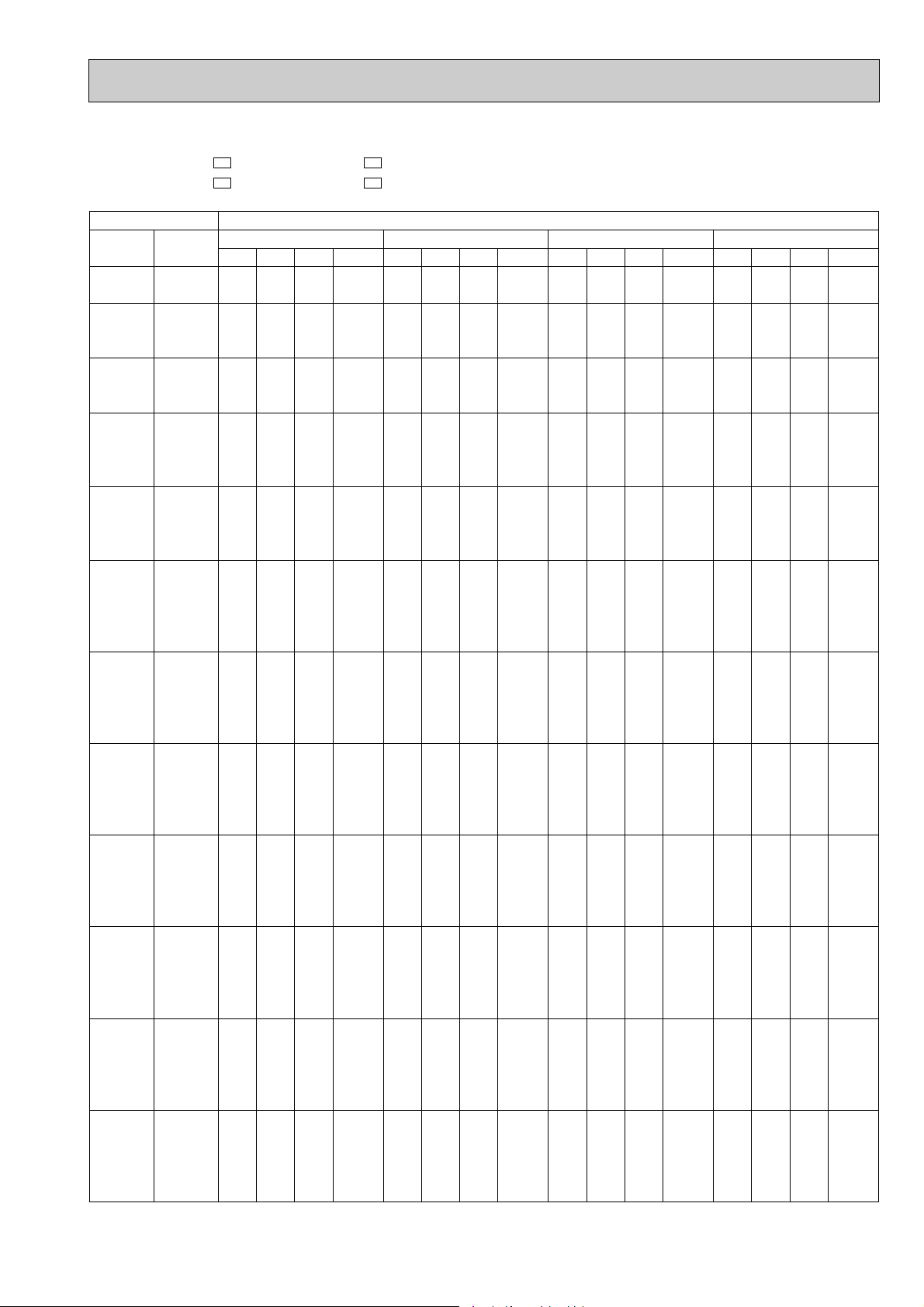
PERFORMANCE DATA COOL operation
MSZ-G09SV - MUZ-G09SV MSZ-G09SV - MUZ-G09SV -
CAPACITY:2.6(KW)
INDOOR INDOOR
DB(;) WB(;)
21 18 3.06 1.53 0.50 752 2.93 1.46 0.50 790 2.81 1.40 0.50 827 2.70 1.35 0.50 865
21 20 3.19 1.21 0.38 790 3.06 1.16 0.38 837 2.96 1.13 0.38 855 2.86 1.09 0.38 893
22 18 3.06 1.65 0.54 752 2.93 1.58 0.54 790 2.81 1.52 0.54 827 2.70 1.46 0.54 865
22 20 3.19 1.34 0.42 790 3.06 1.28 0.42 837 2.96 1.24 0.42 855 2.86 1.20 0.42 893
22 22 3.32 0.99 0.30 818 3.20 0.96 0.30 870 3.12 0.94 0.30 893 2.99 0.90 0.30 931
23 18 3.06 1.77 0.58 752 2.93 1.70 0.58 790 2.81 1.63 0.58 827 2.70 1.57 0.58 865
23 20 3.19 1.47 0.46 790 3.06 1.41 0.46 837 2.96 1.36 0.46 855 2.86 1.32 0.46 893
23 22 3.32 1.13 0.34 818 3.20 1.09 0.34 870 3.12 1.06 0.34 893 2.99 1.02 0.34 931
24 18 3.06 1.89 0.62 752 2.93 1.81 0.62 790 2.81 1.74 0.62 827 2.70 1.68 0.62 865
24 20 3.19 1.59 0.50 790 3.06 1.53 0.50 837 2.96 1.48 0.50 855 2.86 1.43 0.50 893
24 22 3.32 1.26 0.38 818 3.20 1.22 0.38 870 3.12 1.19 0.38 893 2.99 1.14 0.38 931
24 24 3.48 0.91 0.26 855 3.35 0.87 0.26 902 3.28 0.85 0.26 931 3.17 0.82 0.26 978
25 18 3.06 2.02 0.66 752 2.93 1.93 0.66 790 2.81 1.85 0.66 827 2.70 1.78 0.66 865
25 20 3.19 1.72 0.54 790 3.06 1.65 0.54 837 2.96 1.60 0.54 855 2.86 1.54 0.54 893
25 22 3.32 1.39 0.42 818 3.20 1.34 0.42 870 3.12 1.31 0.42 893 2.99 1.26 0.42 931
25 24 3.48 1.05 0.30 855 3.35 1.01 0.30 902 3.28 0.98 0.30 931 3.17 0.95 0.30 978
26 18 3.06 2.14 0.70 752 2.93 2.05 0.70 790 2.81 1.97 0.70 827 2.70 1.89 0.70 865
26 20 3.19 1.85 0.58 790 3.06 1.77 0.58 837 2.96 1.72 0.58 855 2.86 1.66 0.58 893
26 22 3.32 1.52 0.46 818 3.20 1.47 0.46 870 3.12 1.44 0.46 893 2.99 1.38 0.46 931
26 24 3.48 1.18 0.34 855 3.35 1.14 0.34 902 3.28 1.11 0.34 931 3.17 1.08 0.34 978
26 26 3.59 0.79 0.22 902 3.48 0.77 0.22 949 3.43 0.76 0.22 978 3.33 0.73 0.22 1006
27 18 3.06 2.26 0.74 752 2.93 2.16 0.74 790 2.81 2.08 0.74 827 2.70 2.00 0.74 865
27 20 3.19 1.97 0.62 790 3.06 1.89 0.62 837 2.96 1.84 0.62 855 2.86 1.77 0.62 893
27 22 3.32 1.66 0.50 818 3.20 1.60 0.50 870 3.12 1.56 0.50 893 2.99 1.50 0.50 931
27 24 3.48 1.32 0.38 855 3.35 1.27 0.38 902 3.28 1.24 0.38 931 3.17 1.21 0.38 978
27 26 3.59 0.93 0.26 902 3.48 0.91 0.26 949 3.43 0.89 0.26 978 3.33 0.87 0.26 1006
28 18 3.06 2.38 0.78 752 2.93 2.28 0.78 790 2.81 2.19 0.78 827 2.70 2.11 0.78 865
28 20 3.19 2.10 0.66 790 3.06 2.02 0.66 837 2.96 1.96 0.66 855 2.86 1.89 0.66 893
28 22 3.32 1.79 0.54 818 3.20 1.73 0.54 870 3.12 1.68 0.54 893 2.99 1.61 0.54 931
28 24 3.48 1.46 0.42 855 3.35 1.41 0.42 902 3.28 1.38 0.42 931 3.17 1.33 0.42 978
28 26 3.59 1.08 0.30 902 3.48 1.05 0.30 949 3.43 1.03 0.30 978 3.33 1.00 0.30 1006
29 18 3.06 2.51 0.82 752 2.93 2.40 0.82 790 2.81 2.30 0.82 827 2.70 2.22 0.82 865
29 20 3.19 2.23 0.70 790 3.06 2.14 0.70 837 2.96 2.07 0.70 855 2.86 2.00 0.70 893
29 22 3.32 1.92 0.58 818 3.20 1.85 0.58 870 3.12 1.81 0.58 893 2.99 1.73 0.58 931
29 24 3.48 1.60 0.46 855 3.35 1.54 0.46 902 3.28 1.51 0.46 931 3.17 1.46 0.46 978
29 26 3.59 1.22 0.34 902 3.48 1.18 0.34 949 3.43 1.17 0.34 978 3.33 1.13 0.34 1006
30 18 3.06 2.63 0.86 752 2.93 2.52 0.86 790 2.81 2.41 0.86 827 2.70 2.33 0.86 865
30 20 3.19 2.36 0.74 790 3.06 2.26 0.74 837 2.96 2.19 0.74 855 2.86 2.12 0.74 893
30 22 3.32 2.06 0.62 818 3.20 1.98 0.62 870 3.12 1.93 0.62 893 2.99 1.85 0.62 931
30 24 3.48 1.74 0.50 855 3.35 1.68 0.50 902 3.28 1.64 0.50 931 3.17 1.59 0.50 978
30 26 3.59 1.36 0.38 902 3.48 1.32 0.38 949 3.43 1.30 0.38 978 3.33 1.26 0.38 1006
31 18 3.06 2.75 0.90 752 2.93 2.63 0.90 790 2.81 2.53 0.90 827 2.70 2.43 0.90 865
31 20 3.19 2.48 0.78 790 3.06 2.38 0.78 837 2.96 2.31 0.78 855 2.86 2.23 0.78 893
31 22 3.32 2.19 0.66 818 3.20 2.11 0.66 870 3.12 2.06 0.66 893 2.99 1.97 0.66 931
31 24 3.48 1.88 0.54 855 3.35 1.81 0.54 902 3.28 1.77 0.54 931 3.17 1.71 0.54 978
31 26 3.59 1.51 0.42 902 3.48 1.46 0.42 949 3.43 1.44 0.42 978 3.33 1.40 0.42 1006
32 18 3.06 2.87 0.94 752 2.93 2.75 0.94 790 2.81 2.64 0.94 827 2.70 2.54 0.94 865
32 20 3.19 2.61 0.82 790 3.06 2.51 0.82 837 2.96 2.43 0.82 855 2.86 2.35 0.82 893
32 22 3.32 2.32 0.70 818 3.20 2.24 0.70 870 3.12 2.18 0.70 893 2.99 2.09 0.70 931
32 24 3.48 2.02 0.58 855 3.35 1.95 0.58 902 3.28 1.90 0.58 931 3.17 1.84 0.58 978
32 26 3.59 1.65 0.46 902 3.48 1.60 0.46 949 3.43 1.58 0.46 978 3.33 1.53 0.46 1006
NOTE Q :Total capacity (kW) SHF :Sensible heat factor
SHC :Sensible heat capacity (kW) INPUT :Total power input (W)
Q SHC SHF INPUT Q SHC SHF INPUT Q SHC SHF INPUT Q SHC SHF INPUT
INPUT:940(W)SHF:0.68
21 25 27 30
E1E1
E2E2
OUTDOOR DB(;)
21
CAPACITY:2.6(KW)
INPUT:940(W)SHF:0.68
OUTDOOR DB(;)
INDOOR INDOOR
35 40 43 46
DB(;) WB(;)
Q SHC SHF INPUT Q SHC SHF INPUT Q SHC SHF INPUT Q SHC SHF INPUT
21 18 2.55 1.27 0.50 921 2.34 1.17 0.50 978 2.25 1.12 0.50 996 2.16 1.08 0.50 1015
21 20 2.68 1.02 0.38 959 2.50 0.95 0.38 1006 2.41 0.91 0.38 1034 2.31 0.88 0.38 1062
22 18 2.55 1.38 0.54 921 2.34 1.26 0.54 978 2.25 1.21 0.54 996 2.16 1.17 0.54 1015
22 20 2.68 1.12 0.42 959 2.50 1.05 0.42 1006 2.41 1.01 0.42 1034 2.31 0.97 0.42 1062
22 22 2.83 0.85 0.30 996 2.65 0.80 0.30 1053 2.56 0.77 0.30 1072 2.47 0.74 0.30 1090
23 18 2.55 1.48 0.58 921 2.34 1.36 0.58 978 2.25 1.30 0.58 996 2.16 1.25 0.58 1015
23 20 2.68 1.23 0.46 959 2.50 1.15 0.46 1006 2.41 1.11 0.46 1034 2.31 1.06 0.46 1062
23 22 2.83 0.96 0.34 996 2.65 0.90 0.34 1053
2.56 0.87 0.34 1072
2.47 0.84 0.34 1090
24 18 2.55 1.58 0.62 921 2.34 1.45 0.62 978 2.25 1.39 0.62 996 2.16 1.34 0.62 1015
24 20 2.68 1.34 0.50 959 2.50 1.25 0.50 1006 2.41 1.20 0.50 1034 2.31 1.16 0.50 1062
24 22 2.83 1.08 0.38 996 2.65 1.01 0.38 1053 2.56 0.97 0.38 1072 2.47 0.94 0.38 1090
24 24 2.99 0.78 0.26 1034 2.81 0.73 0.26 1081 2.73 0.71 0.26 1105 2.65 0.69 0.26 1128
25 18 2.55 1.68 0.66 921 2.34 1.54 0.66 978 2.25 1.48 0.66 996 2.16 1.42 0.66 1015
25 20 2.68 1.45 0.54 959 2.50 1.35 0.54 1006 2.41 1.30 0.54 1034 2.31 1.25 0.54 1062
25 22 2.83 1.19 0.42 996 2.65 1.11 0.42 1053 2.56 1.08 0.42 1072 2.47 1.04 0.42 1090
25 24 2.99 0.90 0.30 1034 2.81 0.84 0.30 1081 2.73 0.82 0.30 1105 2.65 0.80 0.30 1128
26 18 2.55 1.78 0.70 921 2.34 1.64 0.70 978 2.25 1.57 0.70 996 2.16 1.51 0.70 1015
26 20 2.68 1.55 0.58 959 2.50 1.45 0.58 1006 2.41 1.39 0.58 1034 2.31 1.34 0.58 1062
26 22 2.83 1.30 0.46 996 2.65 1.22 0.46 1053 2.56 1.18 0.46 1072 2.47 1.14 0.46 1090
26 24 2.99 1.02 0.34 1034 2.81 0.95 0.34 1081 2.73 0.93 0.34 1105 2.65 0.90 0.34 1128
26 26 3.15 0.69 0.22 1072 2.96 0.65 0.22 1119 2.87 0.63 0.22 1142 2.78 0.61 0.22 1166
27 18 2.55 1.89 0.74 921 2.34 1.73 0.74 978 2.25 1.66 0.74 996 2.16 1.60 0.74 1015
27 20 2.68 1.66 0.62 959 2.50 1.55 0.62 1006 2.41 1.49 0.62 1034 2.31 1.43 0.62 1062
27 22 2.83 1.42 0.50 996 2.65 1.33 0.50 1053 2.56 1.28 0.50 1072 2.47 1.24 0.50 1090
27 24 2.99 1.14 0.38 1034 2.81 1.07 0.38 1081 2.73 1.04 0.38 1105 2.65 1.01 0.38 1128
27 26 3.15 0.82 0.26 1072 2.96 0.77 0.26 1119 2.87 0.75 0.26 1142 2.78 0.72 0.26 1166
28 18 2.55 1.99 0.78 921 2.34 1.83 0.78 978 2.25 1.75 0.78 996 2.16 1.68 0.78 1015
28 20 2.68 1.77 0.66 959 2.50 1.65 0.66 1006 2.41 1.59 0.66 1034 2.31 1.53 0.66 1062
28 22 2.83 1.53 0.54 996 2.65 1.43 0.54 1053 2.56 1.38 0.54 1072 2.47 1.33 0.54 1090
28 24 2.99 1.26 0.42 1034 2.81 1.18 0.42 1081 2.73 1.15 0.42 1105 2.65 1.11 0.42 1128
28 26 3.15 0.94 0.30 1072 2.96 0.89 0.30 1119 2.87 0.86 0.30 1142 2.78 0.83 0.30 1166
29 18 2.55 2.09 0.82 921 2.34 1.92 0.82 978 2.25 1.84 0.82 996 2.16 1.77 0.82 1015
29 20 2.68 1.87 0.70 959 2.50 1.75 0.70 1006 2.41 1.68 0.70 1034 2.31 1.62 0.70 1062
29 22 2.83 1.64 0.58 996 2.65 1.54 0.58 1053 2.56 1.49 0.58 1072 2.47 1.43 0.58 1090
29 24 2.99 1.38 0.46 1034 2.81 1.29 0.46 1081 2.73 1.26 0.46 1105 2.65 1.22 0.46 1128
29 26 3.15 1.07 0.34 1072 2.96 1.01 0.34 1119 2.87 0.98 0.34 1142 2.78 0.95 0.34 1166
30 18 2.55 2.19 0.86 921 2.34 2.01 0.86 978 2.25 1.93 0.86 996 2.16 1.86 0.86 1015
30 20 2.68 1.98 0.74 959 2.50 1.85 0.74 1006 2.41 1.78 0.74 1034 2.31 1.71 0.74 1062
30 22 2.83 1.76 0.62 996 2.65 1.64 0.62 1053 2.56 1.59 0.62 1072 2.47 1.53 0.62 1090
30 24 2.99 1.50 0.50 1034 2.81 1.40 0.50 1081 2.73 1.37 0.50 1105 2.65 1.33 0.50 1128
30 26 3.15 1.20 0.38 1072 2.96 1.13 0.38 1119 2.87 1.09 0.38 1142 2.78 1.06 0.38 1166
31 18 2.55 2.29 0.90 921 2.34 2.11 0.90 978 2.25 2.02 0.90 996 2.16 1.94 0.90 1015
31 20 2.68 2.09 0.78 959 2.50 1.95 0.78 1006 2.41 1.88 0.78 1034 2.31 1.80 0.78 1062
31 22 2.83 1.87 0.66 996 2.65 1.75 0.66 1053 2.56 1.69 0.66 1072 2.47 1.63 0.66 1090
31 24 2.99 1.61 0.54 1034 2.81 1.52 0.54 1081 2.73 1.47 0.54 1105 2.65 1.43 0.54 1128
31 26 3.15 1.32 0.42 1072 2.96 1.24 0.42 1119 2.87 1.21 0.42 1142 2.78 1.17 0.42 1166
32 18 2.55 2.40 0.94 921 2.34 2.20 0.94 978 2.25 2.11 0.94 996 2.16 2.03 0.94 1015
32 20 2.68 2.20 0.82 959 2.50 2.05 0.82 1006 2.41 1.97 0.82 1034 2.31 1.90 0.82 1062
32 22 2.83 1.98 0.70 996 2.65 1.86 0.70 1053 2.56 1.79 0.70 1072 2.47 1.73 0.70 1090
32 24 2.99 1.73 0.58 1034 2.81 1.63 0.58 1081 2.73 1.58 0.58 1105 2.65 1.54 0.58 1128
32 26 3.15 1.45 0.46 1072 2.96 1.36 0.46 1119 2.87 1.32 0.46 1142 2.78 1.28 0.46 1166
PERFORMANCE DATA COOL operation
MSZ-G09SV - MUZ-G09SV MSZ-G09SV - MUZ-G09SV -
E1E1
E2E2
NOTE Q :Total capacity (kW) SHF :Sensible heat factor
SHC :Sensible heat capacity (kW) INPUT :Total power input (W)
22
 Loading...