Mitsubishi MSX-05NV- E2, MSX-05NV II- E1, MSX-09NV- E2, MSX-09NV II- E1, MSX-12NV- E2 Service Manual
...
SPLIT-TYPE AIR CONDITIONERS
No. OB221
SERVICE MANUAL
Wireless type Models
MSX-05NV- E2
MSX-09NV- E2
MSX-12NV- E2
MSX-05NV2-
MSX-09NV2-
MSX-12NV2-
E1 (WH)
E1 (WH)
E1 (WH)
●MUX-10NV- E1 ●MUX-18NV- E1 ●MUX-24NV- E1 ●MUX-10NV- E1 ●MUX-18NV- E1 ●MUX-24NV- E1
CONTENTS
1. TECHNICAL CHANGES ····································2
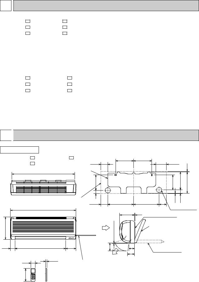
2. OUTLINES AND DIMENSIONS ·························2
3. SERVICE FUNCTIONS ······································3
4. PARTS LIST ··················································· ····4
NOTE: This Service Manual covers only change points. (MSX-05/09/12NV- E1 MSX-05/09/12NV- E2 ) (MSX-05/09/12NV- E2 MSX-05/09/12NV2- E1 ) Please refer to the Service Manual OB183 SECOND EDITION for unchanged contents.
Please refer to the Service Manual OB183 SECOND EDITION for MUX-10/18/24NV- E1 .

1 TECHNICAL CHANGES
MSX-10NV- E1 MSX-10NV- E2
MSX-18NV- E1 MSX-18NV- E2
MSX-24NV- E1 MSX-24NV- E2
1.Auto restart function has added.
2.INDOOR ELECTRONIC CONTROL P.C. BOARD has changed.
MSX-10NV- E2 MSX-10NV2- E1
MSX-18NV- E2 MSX-18NV2- E1
MSX-24NV- E2 MSX-24NV2- E1
1. Indoor unit design has changed.
2 
 OUTLINES AND DIMENSIONS
INDOOR UNIT
MSX-05NV2- E1 MSX-12NV2- E1
275
60
56
160
Unit : mm
, MSX-09NV2- E1 |
84.5 |
|
225 |
225 |
|
133.5 |
|
||
|
|
|
|
|
|
|
|||
|
Installation plate |
|
|
|
|
|
|
9 |
|
783 |
|
|
|
|
|
|
|
||
|
|
|
|
|
|
|
|
|
|
|
|
191 |
|
|
|
|
186 |
223 |
266.5 |
|
Indoor unit |
41 |
|
323 |
314.5 |
93 |
2.5 |
46 |
|
|
|
84.5 |
|
|
|
|
|||
815 |
|
|
|
183 |
|
|
Wall hole {65 |
||
|
|
|
|
5 Installation plate |
|
|
|||
|
|
|
more |
|
|
Liquid line {6.35-0.5m |
|||
|
|
|
|
{Insulation {35 O.D |
|||||
|
|
Air in |
|
|
|
Gas line {9.52-0.43m |
|||
|
|
|
7 or |
|
|
|
{19 I.D |
||
|
|
|
|
|
|
|
|
|
|
625 |
130 |
|
100 |
72 |
|
|
|
|
|
|
|
|
|
|
|
|
|||
|
|
90 |
Drain hose {16 |
|
|
Insulation {28 |
|
17.5 |
Air out |
|
|
|
|
||
|
|
|
Power supply cord
Lead to right 1.0m
Lead to left 0.3m
Wireless remote controller
2

3 
 SERVICE FUNCTIONS
1. AUTO RESTART FUNCTION
When the indoor unit is controlled with the remote controller, the operation mode, set temperature, and the fan speed are memorized by the indoor electronic control P.C.board. The “AUTO RESTART FUNCTION” sets to work the moment power has restored after power failure.Then, the unit will restart automatically. However if the unit is operated in “I FEEL CONTROL.” mode before power failure, the operation is not memorized. In “I FEEL CONTROL.” mode, the operation is decided by the initial room temperature.
How to set “AUTO RESTART FUNCTION”
1Turn off the main power for the unit.
2Removed the electronic control P.C. board and the display P.C.board. (See page 39.) 3Cut the RESISTOR JR07 on the indoor electronic control P.C.board.
C11
52C |
CN211 |
|
|
CN201 |
|
CN112 CN111 |
CN121 |
IC101 |
SW |
|
|
|
CN151 |
JR07
Operation
1If the main power (220-240V AC) has been cut, the operation settings remain.
2After the power is restored, the unit restarts automatically according to the memory.(However, it takes at least 3 minutes for the compressor to start running.)
Note:
•The operation settings are memorized when 10 seconds have passed after the remote controller was operated.
•If main power is cut while AUTO START/STOP timer is active ,the timer setting is cancelled when auto restart function works.
•If the unit has been off with the remote controller before power failure, the auto restart function does not works as the power button of the remote controller is off.
•To prevent breaker off due to the rush of startting current, systematize other home appliance not to turn on at the same time.
•When more than one air conditioners are connected under the same power system,compressor starting current as large as that for all the compressors used flows at a time as soon as the units restart automatically.
Therefore, the specific counter-measures are required to prevent main voltage drop or the rush of starting current after power failure by providing the system to allow the units to start in regular succession.
3
 Loading...