


Revision B:
• E2 has been added.
SPLIT-TYPE, HEAT PUMP AIR CONDITIONERS |
Please void OBH468 REVISED EDITION-A. |
INDOOR UNIT
SERVICE MANUAL
No. OBH468
REVISED EDITION-B
Wireless type
Models
MSZ-GC22VA - E1
MSZ-GC22VA - E2
MSZ-GC25VA - E1
MSZ-GC25VA - E2
MSZ-GC35VA - E1
MSZ-GC35VA - E2
Outdoor unit service manual MUZ-GC·VA Series (OBH469) MXZ-A·VA Series (OB377)
MXZ-8A140A (OC316)
CONTENTS
1. TECHNICAL CHANGES ····································2
2. PART NAMES AND FUNCTIONS······················2
3. SPECIFICATION·················································3
4. NOISE CRITERIA CURVES ·······························4
5. OUTLINES AND DIMENSIONS ·························5
6. WIRING DIAGRAM ············································6
7. REFRIGERANT SYSTEM DIAGRAM ················6
8. SERVICE FUNCTIONS ······································7
9. MICROPROCESSOR CONTROL ······················9
10. TROUBLESHOOTING······································14
11. DISASSEMBLY INSTRUCTIONS·····················26
PARTS CATALOG (OBB468)
NOTE:
RoHS compliant products have <G> mark on the spec name plate.

Revision A:
•10.TROUBLESHOOTING has been corrected.
•Color of lead wire (indoor fan motor : sensor part) of 10-5.”Trouble criterion of main parts” has been corrected.
•10-6.” ACheck of indoor fan motor” has been corrected.
Revision B:
•E2 has been added.
1 
 TECHNICAL CHANGES
MSZ-GA22VA - E1 MSZ-GA25VA - E1 MSZ-GA35VA - E1
MSZ-GC22VA - E1
MSZ-GC25VA - E1
MSZ-GC35VA - E1
1. Indoor model has been changed.
MSZ-GC22VA - E1 MSZ-GC25VA - E1 MSZ-GC35VA - E1
MSZ-GC22VA - E2
MSZ-GC25VA - E2
MSZ-GC35VA - E2
1. Panel has been changed.
2 
 PART NAMES AND FUNCTIONS
MSZ-GC22VA
MSZ-GC25VA
MSZ-GC35VA
Catechin air filter
Air outlet
Vertical vane
Horizontal vane
Air cleaning filter
(Anti-allergy enzyme filter, option)
Air inlet
Front panel
Line flow fan

 Remote controller
Remote control receiving section
Emergency operation switch (E.O. SW) |
Operation Indicator |
|
lamp |
2

MSZ-GC22VA
MSZ-GC25VA
MSZ-GC35VA
ACCESSORIES
1 |
Installation plate |
1 |
|
|
|
2 |
Installation plate fixing screw 4 o 25 mm |
5 |
|
|
|
3 |
Remote controller holder |
1 |
|
|
|
4 |
Fixing screw for 3 3.5 o 1.6 mm (Black) |
2 |
5 |
Battery (AAA) for remote controller |
2 |
6 |
Wireless remote controller |
1 |
7 |
Felt tape (Used for left or left-rear piping) |
1 |
3 
 SPECIFICATION
Indoor model
Function
Power supply
Capacity Air flow(Super High) Air flow(High/Med./Low)
Electrical |
data |
Fan motor current 1 |
|
|
|
Running current 1 |
|
|
|
Power input 1 |
|
Fan motor |
Model |
||
|
|
Dimensions WOHOD |
|
|
|
Weight |
|
|
|
Air direction |
|
|
|
||
Special |
remarks |
Sound level (Super High) |
|
Sound level (High/Med./Low) |
|||
|
|
||
|
|
Fan speed (Super High) |
|
|
|
Fan speed (High/Med./Low) |
|
|
|
Fan speed regulator |
|
|
|
Remote controller model |
|
|
MSZ-GC22VA |
MSZ-GC25VA |
MSZ-GC35VA |
||||||
|
Cooling |
|
Heating |
Cooling |
|
Heating |
Cooling |
|
Heating |
|
|
|
|
||||||
|
|
|
|
Single phase |
|
|
|
||
|
|
|
|
230V,50Hz |
|
|
|
||
K /h |
576 |
|
600 |
576 |
|
600 |
552 |
|
570 |
K /h |
462/354/246 |
|
480/378/276 |
462/354/246 |
|
480/378/276 |
444/330/234 |
|
462/354/246 |
A |
|
|
|
0.22 |
|
|
|
||
W |
|
|
|
40 |
|
|
|
||
A |
|
|
|
0.22 |
|
|
|
||
|
|
|
|
RC4V18-BA or CA |
|
|
|
||
mm |
|
|
|
788O295O234 |
|
|
|
||
kg |
|
|
|
|
9 |
|
|
|
|
|
|
|
|
|
4 |
|
|
|
|
dB(A) |
|
|
|
43 |
|
|
|
||
dB(A) |
|
36/29/21 |
|
|
36/29/22 |
||||
rpm |
1,070 |
1,100 |
1,070 |
|
1,100 |
1,110 |
|
1,140 |
|
rpm |
890/720/550 |
920/760/600 |
890/720/550 |
|
920/760/600 |
930/740/580 |
|
960/780/600 |
|
|
|
|
|
|
4 |
|
|
|
|
|
|
|
|
KM05B |
|
|
|
||
NOTE : Test conditions are based on ISO 5151
Cooling : Indoor |
Dry-bulb temperature 27:Wet-bulb temperature 19: |
Outdoor |
Dry-bulb temperature 35: |
Heating : Indoor |
Dry-bulb temperature 20: |
Outdoor Dry-bulb temperature 7:Wet-bulb temperature 6: Refrigerant piping length (one way): 5m
1 Measured under rated operating frequency.
Specifications and rating conditions of main electric parts
Fuse |
(F11) |
T3.15AL 250V |
|
|
|
Horizontal vane motor |
(MV) |
12V DC |
Varistor |
(NR11) |
S10K320E3K1(ERZV14D471) |
Terminal block |
(TB) |
3P |
|
|
|
3

4 NOISE CRITERIA CURVES
MSZ-GC22VA
MSZ-GC25VA
FAN SPEED FUNCTION SPL(dB(A)) |
LINE |
|
|
|
Super High |
COOLING |
43 |
|
|
||
|
|
|
HEATING |
43 |
|
|
|||
|
|
|
|
|
|
|
|||
BAR |
90 |
|
|
|
|
|
|
|
|
|
|
|
|
|
|
|
|
|
|
MICRO |
80 |
|
|
|
|
|
|
|
|
|
|
|
|
|
|
|
|
|
|
0.0002 |
70 |
|
|
|
|
|
|
|
NC-70 |
|
|
|
|
|
|
|
|
||
dB re |
60 |
|
|
|
|
|
|
|
|
LEVEL, |
|
|
|
|
|
|
|
|
|
|
|
|
|
|
|
|
|
NC-60 |
|
50 |
|
|
|
|
|
|
|
|
|
PRESSURE |
|
|
|
|
|
|
|
|
|
|
|
|
|
|
|
|
|
NC-50 |
|
40 |
|
|
|
|
|
|
|
|
|
|
|
|
|
|
|
|
|
NC-40 |
|
SOUND |
|
|
|
|
|
|
|
|
|
30 |
|
|
|
|
|
|
|
|
|
BAND |
|
|
|
|
|
|
|
|
NC-30 |
20 |
APPROXIMATE |
|
|
|
|
|
|
||
OCTAVE |
|
|
|
|
|
|
|||
THRESHOLD OF |
|
|
|
|
|
|
|||
|
|
|
|
|
|
|
|||
|
HEARING FOR |
|
|
|
|
|
NC-20 |
||
|
CONTINUOUS |
|
|
|
|
|
|
||
10 |
NOISE |
|
|
|
|
|
|
|
|
|
63 |
125 |
250 |
500 |
1000 |
2000 |
4000 |
8000 |
|
|
|
||||||||
BAND CENTER FREQUENCIES, Hz
MSZ-GC35VA
FAN SPEED FUNCTION SPL(dB(A)) |
LINE |
|
|
|
Super High |
COOLING |
43 |
|
|
||
|
|
|
HEATING |
43 |
|
|
|||
|
|
|
|
|
|
|
|||
BAR |
90 |
|
|
|
|
|
|
|
|
|
|
|
|
|
|
|
|
|
|
MICRO |
80 |
|
|
|
|
|
|
|
|
|
|
|
|
|
|
|
|
|
|
0.0002 |
70 |
|
|
|
|
|
|
|
NC-70 |
|
|
|
|
|
|
|
|
||
dB re |
60 |
|
|
|
|
|
|
|
|
LEVEL, |
|
|
|
|
|
|
|
|
|
|
|
|
|
|
|
|
|
NC-60 |
|
50 |
|
|
|
|
|
|
|
|
|
PRESSURE |
|
|
|
|
|
|
|
|
|
|
|
|
|
|
|
|
|
NC-50 |
|
40 |
|
|
|
|
|
|
|
|
|
|
|
|
|
|
|
|
|
NC-40 |
|
SOUND |
|
|
|
|
|
|
|
|
|
30 |
|
|
|
|
|
|
|
|
|
BAND |
|
|
|
|
|
|
|
|
NC-30 |
20 |
APPROXIMATE |
|
|
|
|
|
|
||
OCTAVE |
|
|
|
|
|
|
|||
THRESHOLD OF |
|
|
|
|
|
|
|||
|
|
|
|
|
|
|
|||
|
HEARING FOR |
|
|
|
|
|
NC-20 |
||
|
CONTINUOUS |
|
|
|
|
|
|
||
10 |
NOISE |
|
|
|
|
|
|
|
|
|
63 |
125 |
250 |
500 |
1000 |
2000 |
4000 |
8000 |
|
|
|
||||||||
BAND CENTER FREQUENCIES, Hz
Test conditions
Cooling : Dry-bulb temperature 27: Wet-bulb temperature 19: Heating : Dry-bulb temperature 20:
INDOOR UNIT
WALL
1m
0.8m
MICROPHONE
4
5 
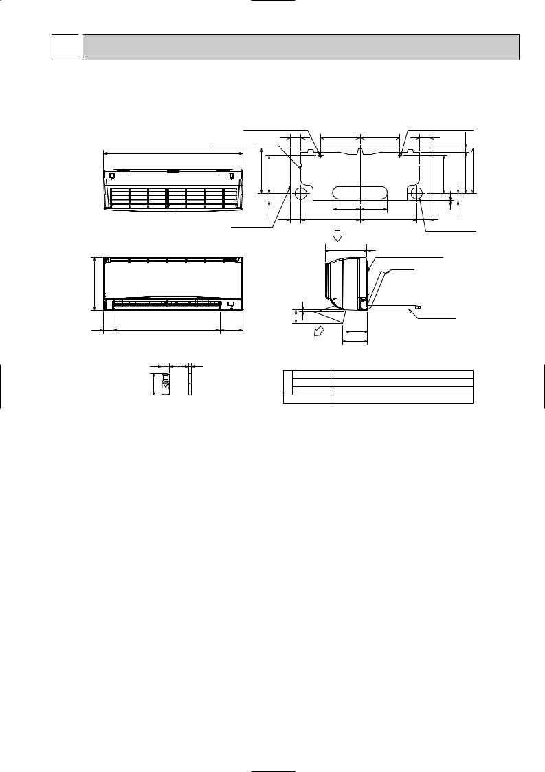
 OUTLINES AND DIMENSIONS
MSZ-GC22VA
MSZ-GC25VA
MSZ-GC35VA
11 X 26 Oblong hole
59
Installation plate
788
254.5 |
215 |
40.5 |
59 |
|
Indoor unit
295
8
Unit : mm
11 X 20 Oblong hole
225 |
225 |
59 |
|
18.5 |
|
|
|
|
|
|
|
|
|
214 |
|
235 |
253.5 |
155 |
155 |
|
2 |
41.5 |
|
335 |
320 |
74 |
|
||
Air in |
|
Wall hole [65 |
|||
234 |
5 |
|
|
|
|
|
Installation plate |
|
|
|
|
Piping
|
|
|
100 |
|
53 |
607 |
128 |
|
119 |
|
|
|
Air out |
137 |
|
|
|
|
|
|
58 |
19 |
|
|
Drain hose
159
Piping
Insulation Liquid line Gas line Drain hose
[35 O.D
[6.35 - 0.5 m (Flared connection [6.35) [9.52 - 0.43 m (Flared connection [9.52) Insulation [28 O.D Connected part [16 O.D
5

6 
 WIRING DIAGRAM
MSZ-GC22VA
MSZ-GC25VA
MSZ-GC35VA
7 
 REFRIGERANT SYSTEM DIAGRAM
MSZ-GC22VA MSZ-GC25VA MSZ-GC35VA
Unit : mm
|
|
Refrigerant pipe [9.52 |
|
|
(with heat insulator) |
Indoor |
Indoor coil |
|
thermistor |
|
|
heat |
|
|
exchanger |
RT12 (main) |
Flared connection |
Indoor coil thermistor RT13 (sub)
Room temperature thermistor
RT11
Flared connection
Refrigerant pipe [6.35 (with heat insulator)
 Refrigerant flow in cooling
Refrigerant flow in heating
6

8 
 SERVICE FUNCTIONS
MSZ-GC22VA
MSZ-GC25VA
MSZ-GC35VA
8-1. TIMER SHORT MODE
For service, set time can be shortened by short circuit of JPG and JPS on the electronic control P.C. board. The time will be shortened as follows. (Refer to 10-7.)
Set time : 1-minute 1-second
Set time : 3-minute 3-second (It takes 3 minutes for the compressor to start operation. However, the starting time is shortened by short circuit of JPG and JPS.)
8-2. P.C. BOARD MODIFICATION FOR INDIVIDUAL OPERATION
A maximum of 4 indoor units with wireless remote controllers can be used in a room.
In this case, to operate each indoor unit individually by each remote controller, P.C. boards of remote controller must be modified according to the number of the indoor unit.
How to modify the remote controller P.C. board
Remove batteries before modification.
The board has a print as shown below :
NOTE : For modification, take out the batteries and press the OPERATE/STOP(ON/OFF) button twice or 3 times at first.
After modification, put back the batteries then press
the RESET button.
J1 J2
The P.C. board has the print “J1” and “J2”. Solder “J1” and “J2” according to the number of indoor unit as shown in Table 1. After modification, press the RESET button.
Table 1
|
1 unit operation |
2 units operation |
3 units operation |
4 units operation |
No. 1 unit |
No modification |
Same as at left |
Same as at left |
Same as at left |
|
|
|
|
|
No. 2 unit |
– |
Solder J1 |
Same as at left |
Same as at left |
|
|
|
|
|
No. 3 unit |
– |
– |
Solder J2 |
Same as at left |
|
|
|
|
|
No. 4 unit |
– |
– |
– |
Solder both J1 and J2 |
|
|
|
|
|
How to set the remote controller exclusively for particular indoor unit
After you turn the breaker ON, the first remote controller that sends the signal to the indoor unit will be regarded as the remote controller for the indoor unit.
The indoor unit will only accept the signal from the remote controller that has been assigned to the indoor unit once they are set.
The setting will be cancelled if the breaker is turned OFF, or the power supply is shut down. Please conduct the above setting once again after the power has restored.
7

8-3. AUTO RESTART FUNCTION
When the indoor unit is controlled with the remote controller, the operation mode, the set temperature, and the fan speed are memorized by the indoor electronic control P.C. board. “AUTO RESTART FUNCTION” automatically starts operation in the same mode just before the shutoff of the main power.
Operation
1 If the main power has been cut, the operation settings remain.
2 After the power is restored, the unit restarts automatically according to the memory. (However, it takes at least 3 minutes for the compressor to start running.)
How to release “AUTO RESTART FUNCTION”
1Turn off the main power for the unit.
2Solder the jumper wire to JR07 on the indoor electronic control P.C. board. (Refer to 10-7.)
Indoor electronic control P.C. board
JR07 
 CN10A CN151 CN112 CN111
NOTE :
•The operation settings are memorized when 10 seconds have passed after the indoor unit was operated with the remote controller.
•If main power is turned OFF or a power failure occurs while AUTO START/STOP timer is active, the timer setting is cancelled.
•If the unit has been off with the remote controller before power failure, the auto restart function does not work as the power button of the remote controller is off.
•To prevent breaker OFF due to the rush of starting current, systematize other home appliance not to turn ON at the same time.
•When some air conditioners are connected to the same supply system, if they are operated before power failure, the starting current of all the compressors may flow simultaneously at restart.
Therefore, the special counter-measures are required to prevent the main voltage-drop or the rush of the starting current by adding to the system that allows the units to start one by one.
8

9 
 MICROPROCESSOR CONTROL
MSZ-GC22VA
MSZ-GC25VA
MSZ-GC35VA
WIRELESS REMOTE CONTROLLER
Signal transmitting section 
Operation display section |
|
|
OPERATE/STOP |
FAN SPEED CONTROL button |
|
(ON/OFF) button |
OPERATION SELECT button |
OFF TIMER button |
|
||
|
ECONO COOL button |
ON TIMER button |
Open the front lid. |
Temperature buttons |
TIME SET buttons |
|
FORWARD button |
|
|
|
BACKWARD button |
|
RESET button |
CLOCK SET button |
|
VANE CONTROL button |
|
|
|
|
|
Indication of |
|
|
remote controller |
|
|
model is on back |
|
Once the operation mode is set, the same operation mode can be repeated by simply turning OPERATE/STOP (ON/OFF) button ON.
Indoor unit receives the signal with a beep tone.
When the system turns off, 3-minute time delay will operate to protect system from overload and compressor will not restart for 3 minutes.
INDOOR UNIT DISPLAY SECTION
Operation Indicator lamp
The operation indicator at the right side of the indoor unit indicates the operation state.
•The following indication applies regardless of shape of the indicator.
Indication |
Operation state |
Room temperature |
|
The unit is operating |
About 2 : or more |
|
to reach the set |
away from |
|
temperature |
set temperature |
|
The room temperature |
About 1 to 2 : from |
|
is approaching |
|
|
set temperature |
|
|
the set temperature |
|
|
|
|
|
Standby mode |
|
|
(only during multi |
|
|
system operation) |
|
 Lighted
 Blinking
Not lighted
9
 Loading...