


Mitsubishi Electronics MSZ-EF09NAW, MSZ-EF12NAW, MSZ-EF15NAW, MSZ-EF18NAW, MSZ-EF09NAB User Manual
...INDOOR UNIT
SERVICE MANUAL |
No. OBH736 |
|
Models
MSZ-EF09NAW - U1 MSZ-EF15NAW - U1 MSZ-EF09NAB - U1 MSZ-EF15NAB - U1 MSZ-EF09NAS - U1 MSZ-EF15NAS - U1
MSZ-EF12NAW - U1 MSZ-EF18NAW - U1 MSZ-EF12NAB - U1 MSZ-EF18NAB - U1 MSZ-EF12NAS - U1 MSZ-EF18NAS - U1
Outdoor unit service manual MXZ- ∙C∙NA(HZ) Series (OCH573)
CONTENTS
1.TECHNICAL CHANGES ······························2
2.PART NAMES AND FUNCTIONS··················3
3.SPECIFICATION ········································4
4.OUTLINES AND DIMENSIONS·····················6
5.WIRING DIAGRAM·····································7
6.REFRIGERANT SYSTEM DIAGRAM ·············8
7.SERVICE FUNCTIONS································9
8.MICROPROCESSOR CONTROL ················ 11
9.TROUBLESHOOTING······························· 19
10.DISASSEMBLY INSTRUCTIONS················· 31
PARTS CATALOG (OBB736)
NOTE:
RoHS compliant products have <G> mark on the spec name plate.
Use the specified refrigerant only
Never use any refrigerant other than that specified.
Doing so may cause a burst, an explosion, or fire when the unit is being used, serviced, or disposed of. Correct refrigerant is specified in the manuals and on the spec labels provided with our products.
We will not be held responsible for mechanical failure, system malfunction, unit breakdown or accidents caused by failure to follow the instructions.
1 
 TECHNICAL CHANGES
MSZ-EF09NAW - MSZ-EF09NAB - MSZ-EF09NAS -
1. New model
U1
U1
U1
MSZ-EF12NAW - MSZ-EF12NAB - MSZ-EF12NAS -
U1
U1
U1
MSZ-EF15NAW - MSZ-EF15NAB - MSZ-EF15NAS -
U1
U1
U1
MSZ-EF18NAW - MSZ-EF18NAB - MSZ-EF18NAS -
U1
U1
U1
OBH736 |
2 |
|
2 
 PART NAMES AND FUNCTIONS
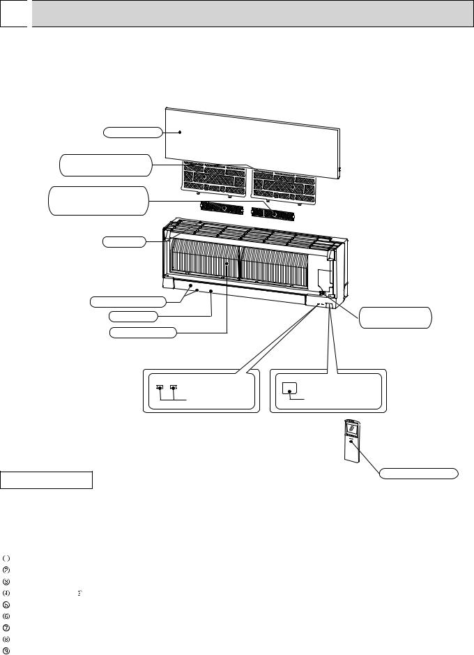
MSZ-EF09NAW MSZ-EF09NAB MSZ-EF09NAS
MSZ-EF12NAW MSZ-EF12NAB MSZ-EF12NAS
MSZ-EF15NAW MSZ-EF15NAB MSZ-EF15NAS
MSZ-EF18NAW MSZ-EF18NAB MSZ-EF18NAS
Front panel
Air ¿lter
(Nano platinum ¿lter)
Air cleaning ¿lter (Electrostatic anti-allergy enzyme ¿lter)
Air inlet
Horizontal vane
Air outlet
Heat exchanger
Emergency operation switch
Operation |
Remote control |
indicator lamp |
receiving section |
ACCESSORIES
Remote controller
|
|
MSZ-EF09NAW |
MSZ-EF12NAW MSZ-EF15NAW MSZ-EF18NAW |
|
Model |
MSZ-EF09NAB |
MSZ-EF12NAB MSZ-EF15NAB MSZ-EF18NAB |
|
|
MSZ-EF09NAS MSZ-EF12NAS MSZ-EF15NAS MSZ-EF18NAS |
|
|
|
|
|
|
Installation plate |
|
1 |
|
Installation plate fixing screw 4 × 25 mm |
|
5 |
|
Remote controller holder |
|
1 |
|
Fixing screw for 3.5 × 16 mm (Black) |
|
2 |
|
Battery (AAA) for remote controller |
|
2 |
|
Wireless remote controller |
|
1 |
|
Felt tape (For left or left-rear piping) |
|
1 |
|
Soft dry cloth (NAB type only) |
|
1 |
|
Air cleaning filter |
|
2 |
OBH736 |
3 |
|

3 |
|
|
SPECIFICATION |
|
|
|
|
|
|
|
|
|
|
|
|
|
|
|
|||||
Indoor unit model |
|
|
MSZ-EF09NAW |
MSZ-EF12NAW |
MSZ-EF15NAW |
MSZ-EF18NAW |
|||||
|
|
|
|
|
|
MSZ-EF09NAB |
MSZ-EF12NAB |
MSZ-EF15NAB |
MSZ-EF18NAB |
||
|
|
|
|
|
|
MSZ-EF09NAS |
MSZ-EF12NAS |
MSZ-EF15NAS |
MSZ-EF18NAS |
||
Power supply |
V, phase, Hz |
|
208/230 , 1 , 60 |
|
|
||||||
Disconnect switch |
|
A |
|
|
15 |
|
|
||||
Min. circuit ampacity |
|
A |
|
|
1.0 |
|
|
||||
Fan motor |
|
|
F.L.A |
|
|
0.67 |
|
|
|||
Airflow |
|
COOL Dry |
CFM |
371 - 293 - 222 - 162 - 141 |
371 - 293 - 222 - 162 |
- 141 |
364 - 314 - 272 - 233 - 205 |
388 - 328 - 279 - 240 - 205 |
|||
|
(Wet) |
(319 - 252 - 191 - 140 - 121) |
(319 - 252 - 191 - 140 |
- 121) |
(313 - 270 - 234 - 200 - 176) |
(334 - 282 - 240 - 206 - 176) |
|||||
Super high - High - Med. - Low - Quiet |
|
|
|
|
|
|
|
||||
HEAT Dry |
CFM |
420 - 314 - 219 - 162 - 141 |
448 - 314 - 219 - 162 |
- 141 |
448 - 350 - 275 - 222 - 194 |
466 - 392 - 318 - 258 - 226 |
|||||
Moisture removal |
|
pt./h |
0.6 |
2.1 |
|
3.6 |
4.4 |
|
|||
Sound level |
Cooling |
dB(A) |
42 - 36 - 29 - 23 - 21 |
42 - 36 - 29 - 24 |
- 21 |
42 - 39 - 35 - 31 - 28 |
43 - 40 - 36 - 33 - 30 |
||||
Super high - High - Med. - Low - Quiet |
Heating |
dB(A) |
45 - 37 - 29 - 24 - 21 |
46 - 38 - 30 - 24 |
- 21 |
48 - 41 - 35 - 30 - 28 |
49 - 43 - 37 - 33 - 30 |
||||
|
|
|
|
|
|
|
|
|
|||
Cond. drain connection O.D. |
|
in. |
|
|
5/8 |
|
|
||||
|
|
|
|
W |
|
|
34-13/16 |
|
|
||
Dimensions |
D |
in. |
|
|
7-11/16 |
|
|
||||
|
|
|
|
H |
|
|
|
11-3/4 |
|
|
|
Weight |
|
|
Ib. |
|
|
26 |
|
|
|||
|
|
|
|
|
|
|
W: Munsell 1.0Y 9.2/0.2 |
|
|
||
External finish |
|
|
|
B: Munsell 3.7PB 2.0/0.1 |
|
|
|||||
|
|
|
|
|
|
|
S: Munsell 3.1PB 8.2/0.2 |
|
|
||
Remote controller |
|
|
|
Wireless type |
|
|
|||||
Control voltage (by built-in transformer) |
|
|
12 - 24 VDC |
|
|
||||||
NOTE: Test conditions are based on AHRI 210/240.
3-1. OPERATING RANGE
(1) POWER SUPPLY
|
Rated voltage |
Guaranteed voltage (V) |
||||||
|
208/230 V |
Min. 187 208 |
230 Max. 253 |
|||||
Indoor unit |
1 phase |
|||||||
|
|
|
|
|
|
|||
|
60 Hz |
|
|
|
|
|
|
|
|
|
|
|
|
|
|
||
(2) OPERATION
Mode |
Condition |
|
|
Intake air temperature (°F) |
|
|
|
Indoor |
|
|
Outdoor |
||||
|
|
DB |
|
WB |
DB |
|
WB |
|
Standard temperature |
80 |
|
67 |
95 |
|
— |
Cooling |
Maximum temperature |
90 |
|
73 |
115 |
|
— |
Minimum temperature |
67 |
|
57 |
14 |
|
— |
|
|
|
|
|||||
|
Maximum humidity |
78% |
|
|
— |
||
Heating |
Standard temperature |
70 |
|
60 |
47 |
|
43 |
Maximum temperature |
80 |
|
67 |
75 |
|
65 |
|
|
Minimum temperature |
70 |
|
60 |
-13 |
|
-14 |
OBH736 |
4 |
|

3-2. OUTLET AIR SPEED AND COVERAGE
Model |
Mode |
Function |
Airflow |
Air speed |
Coverage (ft.) |
|
|
|
|
|
(CFM) |
(ft./s) |
|
● The air coverage is the figure up to the |
|
MSZ-EF09NAW |
HEAT |
Dry |
420 |
19.5 |
29.2 |
||
position where the air speed is 1 ft./s, |
|||||||
MSZ-EF09NAB |
COOL |
Dry |
371 |
17.2 |
25.8 |
when air is blown out horizontally from |
|
MSZ-EF09NAS |
Wet |
319 |
15.5 |
23.3 |
the unit properly at the High speed |
||
|
|||||||
MSZ-EF12NAW |
HEAT |
Dry |
448 |
20.8 |
31.1 |
position. |
|
MSZ-EF12NAB |
COOL |
Dry |
371 |
17.2 |
25.8 |
The coverage should be used only |
|
MSZ-EF12NAS |
Wet |
319 |
15.5 |
23.3 |
as a general guideline since it varies |
||
|
|||||||
|
|
|
|
|
|
according to the size of the room and |
|
MSZ-EF15NAW |
HEAT |
Dry |
448 |
20.8 |
31.1 |
||
furniture arranged inside the room. |
|||||||
MSZ-EF15NAB |
COOL |
Dry |
364 |
16.8 |
25.4 |
||
|
|||||||
MSZ-EF15NAS |
|
|
|
|
|
||
Wet |
313 |
15.2 |
22.9 |
|
|||
|
|
||||||
MSZ-EF18NAW |
HEAT |
Dry |
466 |
21.6 |
32.3 |
|
|
MSZ-EF18NAB |
COOL |
Dry |
388 |
20.3 |
30.4 |
|
|
MSZ-EF18NAS |
Wet |
336 |
18.3 |
27.4 |
|
||
|
|
OBH736 |
5 |
|
4 
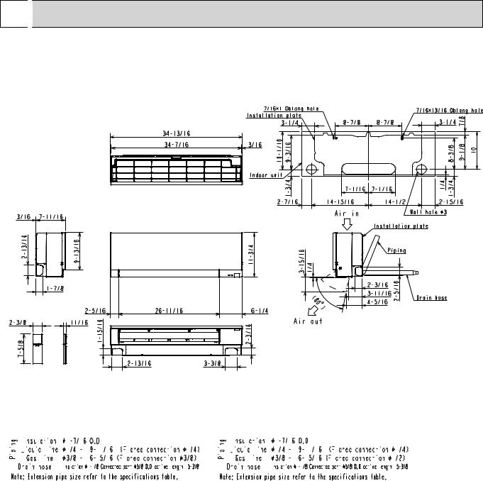
 OUTLINES AND DIMENSIONS
MSZ-EF09NAW MSZ-EF09NAB MSZ-EF09NAS
MSZ-EF12NAW MSZ-EF12NAB MSZ-EF12NAS
MSZ-EF15NAW MSZ-EF15NAB MSZ-EF15NAS
MSZ-EF18NAW
MSZ-EF18NAB
MSZ-EF18NAS
Unit: inch
MSZ-EF09/12NA |
|
MSZ-EF15/18NA |
|||||||||||||||||||||||||||||||||||||||||||||||||||||||||||||||||||||||||||||||||||||||||||
|
|
|
|
|
|
|
|
|
|
|
|
|
|
|
|
|
|
|
|
|
|
|
|
|
|
|
|
|
|
|
|
|
|
|
|
|
|
|
|
|
|
|
|
|
|
|
|
|
|
|
|
|
|
|
|
|
|
|
|
|
|
|
|
|
|
|
|
|
|
|
|
|
|
|
|
|
|
|
|
|
|
|
|
|
|
|
|
|
|
|
|
|
|
|
|
|
|
|
|
|
|
|
|
|
|
|
|
|
|
|
|
|
|
|
|
|
|
|
|
|
|
|
|
|
|
|
|
|
|
|
|
|
|
|
|
|
|
|
|
|
|
|
|
|
|
|
|
|
|
|
|
|
|
|
|
|
|
|
|
|
|
|
|
|
|
|
|
|
|
|
|
|
|
|
|
|
|
|
|
|
|
|
|
|
|
|
|
|
|
|
|
|
|
|
|
|
|
|
|
|
|
|
|
|
|
|
|
|
|
|
|
|
|
|
|
|
|
|
|
|
|
|
|
|
|
|
|
|
|
|
|
|
|
|
|
|
|
|
|
|
|
|
|
|
|
|
|
|
|
|
|
|
|
|
|
|
|
|
|
|
|
|
|
|
|
|
|
|
|
|
|
|
|
|
|
|
|
|
|
|
|
|
|
|
|
|
|
|
|
|
|
|
|
|
|
|
|
|
|
|
|
|
|
|
|
|
|
|
|
|
|
|
|
|
|
|
|
|
|
|
|
|
|
|
|
|
|
|
|
|
|
|
|
|
|
|
|
|
|
|
|
|
|
|
|
|
|
|
|
|
|
|
|
|
|
|
|
|
|
|
|
|
|
|
|
|
|
|
|
|
|
|
|
|
|
|
|
|
|
|
|
|
|
|
|
|
|
|
|
|
|
|
|
|
|
|
|
|
|
|
|
|
|
|
|
|
|
|
|
|
|
|
|
|
|
|
|
|
|
|
|
|
|
|
|
|
|
|
|
|
|
|
|
|
|
|
|
|
|
|
|
|
|
|
|
|
|
|
|
|
|
|
|
|
|
|
|
|
|
|
|
|
|
|
|
|
|
|
|
|
|
|
|
|
|
|
|
|
|
|
|
|
|
|
|
|
|
|
|
|
|
|
|
|
|
|
|
|
|
|
|
|
|
|
|
|
|
|
|
|
|
|
|
|
|
|
|
|
|
|
|
|
|
|
|
|
|
|
|
|
|
|
|
|
|
|
|
|
|
|
|
|
|
|
|
|
|
|
|
|
|
|
|
|
|
|
|
|
|
|
|
|
|
|
|
|
|
|
|
|
|
|
|
|
|
|
|
|
|
|
|
|
|
|
|
|
|
|
|
|
|
|
|
|
|
|
|
|
|
|
|
|
|
|
|
|
|
|
|
|
|
|
|
|
|
|
|
|
|
|
|
|
|
|
|
|
|
|
|
|
|
|
|
|
|
|
|
|
|
|
|
|
|
|
|
|
|
|
|
|
|
|
|
|
|
|
|
|
|
|
|
|
|
|
|
|
|
|
|
|
|
|
|
|
|
|
|
|
|
|
|
|
|
|
|
|
|
|
|
|
|
|
|
|
|
|
|
|
|
|
|
|
|
|
|
|
|
|
|
|
|
|
|
|
|
|
|
|
|
|
|
|
|
|
|
|
|
|
|
|
|
|
|
|
|
|
|
|
|
|
|
|
|
|
|
|
|
|
|
|
|
|
|
|
|
|
|
|
|
|
|
|
|
|
|
|
|
|
|
|
|
|
|
|
|
|
|
|
|
|
|
|
|
|
|
|
|
|
|
|
|
|
|
|
|
|
|
|
|
|
|
|
|
|
|
|
|
|
|
|
|
|
|
|
|
|
|
|
|
|
|
|
|
|
|
|
|
|
|
|
|
|
|
|
|
|
|
|
|
|
|
|
|
|
|
|
|
|
|
|
|
|
|
|
|
|
|
|
|
|
|
|
|
|
|
|
|
|
|
|
|
|
|
|
|
|
|
|
|
|
|
|
|
|
|
|
|
|
|
|
|
|
|
|
|
|
|
|
|
|
|
|
|
|
|
|
|
|
|
|
|
|
|
|
|
|
|
|
|
|
|
|
|
|
|
|
|
|
|
|
|
|
|
|
|
|
|
|
|
OBH736 |
6 |
|

5 
 WIRING DIAGRAM
MSZ-EF09NAW MSZ-EF09NAB MSZ-EF09NAS
MSZ-EF12NAW MSZ-EF12NAB MSZ-EF12NAS
MSZ-EF15NAW MSZ-EF15NAB MSZ-EF15NAS
MSZ-EF18NAW MSZ-EF18NAB MSZ-EF18NAS
OBH736 |
7 |
|
6 
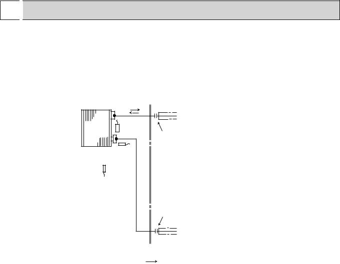
 REFRIGERANT SYSTEM DIAGRAM
MSZ-EF09NAW MSZ-EF09NAB MSZ-EF09NAS
MSZ-EF12NAW MSZ-EF12NAB MSZ-EF12NAS
MSZ-EF15NAW MSZ-EF15NAB MSZ-EF15NAS
MSZ-EF18NAW MSZ-EF18NAB MSZ-EF18NAS
Unit: inch (mm)
Refrigerant pipe ø3/8 (ø9.52) (MSZ-EF09/12) ø1/2 (ø12.7) (MSZ-EF15/18)
|
|
(with heat insulator) |
Indoor |
Indoor coil |
|
thermistor |
|
|
heat |
|
|
RT12 (main) |
|
|
exchanger |
Flared connection |
Indoor coil thermistor RT13 (sub)
Room temperature thermistor
RT11
Flared connection
Refrigerant pipe ø1/4 (ø6.35) (with heat insulator)
 Refrigerant flow in cooling
Refrigerant flow in heating
OBH736 |
8 |
|

7 
 SERVICE FUNCTIONS
MSZ-EF09NAW |
MSZ-EF12NAW |
MSZ-EF09NAB |
MSZ-EF12NAB |
MSZ-EF09NAS |
MSZ-EF12NAS |
7-1. TIMER SHORT MODE |
|
MSZ-EF15NAW MSZ-EF15NAB MSZ-EF15NAS
MSZ-EF18NAW MSZ-EF18NAB MSZ-EF18NAS
For service, the following set time can be shortened by bridging JPG and JPS on the electronic control P.C. board. (Refer to 9-7.)
•The set time for the ON/OFF timer can be reduced to 1 second for each minutes.
•After the breaker is turned on, the time for starting the compressor, which normally takes 3 minuets, can be reduced to 3 seconds. Restarting the compressor, which takes 3 minuets, cannot be reduced.
7-2. HOW TO SET REMOTE CONTROLLER EXCLUSIVELY FOR A PARTICULAR INDOOR UNIT
A maximum of 4 indoor units with wireless remote controllers can be used in a room.
To operate the indoor units individually with each remote controller, assign a number to each remote controller according to the number of the indoor unit.
This setting can be set only when all the following conditions are met:
•The remote controller is powered OFF.
•Weekly timer is not set.
•Weekly timer is not being edited.
(1)Hold down  button on the remote controller for 2 seconds to enter the pairing mode.
(2)Press  button again and assign a number to each remote controller.
Each press of  button advances the number in the following order: 1 → 2 → 3 → 4.
(3)Press  button to complete the pairing setting.
After you turn the breaker ON, the remote controller that first sends a signal to an indoor unit will be regarded as the remote controller for the indoor unit.
Once they are set, the indoor unit will only receive the signal from the assigned remote controller afterwards.
OBH736 |
9 |
|
7-3. AUTO RESTART FUNCTION
When the indoor unit is controlled with the remote controller, the operation mode, the set temperature, and the fan speed are memorized by the indoor electronic control P.C. board. “AUTO RESTART FUNCTION” automatically starts operation in the same mode just before the shutoff of the main power.
Operation
 If the main power has been cut, the operation settings remain.
 After the power is restored, the unit restarts automatically according to the memory. (However, it takes at least 3 minutes for the compressor to start running.)
How to disable “AUTO RESTART FUNCTION”
 Turn off the main power for the unit.
 Cut the jumper wire to JR77 on the indoor electronic control P.C. board. (Refer to 9-7.)
Indoor electronic |
|
control P.C. board |
|
IC171 |
|
CN104 |
|
CN112 |
BZ |
JR77 |
|
NOTE:
•The operation settings are memorized when 10 seconds have passed after the indoor unit was operated with the remote controller.
•If main power is turned OFF or a power failure occurs while AUTO START/STOP timer is active, the timer setting is cancelled.
•If the unit has been off with the remote controller before power failure, the auto restart function does not work as the power button of the remote controller is OFF.
•To prevent breaker OFF due to the rush of starting current, systematize other home appliance not to turn ON at the same time.
•When some air conditioners are connected to the same supply system, if they are operated before power failure, the starting current of all the compressors may flow simultaneously at restart.
Therefore, the special counter-measures are required to prevent the main voltage-drop or the rush of the starting current by adding to the system that allows the units to start one by one.
OBH736 |
10 |
|
8 
 MICROPROCESSOR CONTROL
MSZ-EF09NAW |
MSZ-EF12NAW |
MSZ-EF15NAW |
MSZ-EF09NAB |
MSZ-EF12NAB |
MSZ-EF15NAB |
MSZ-EF09NAS |
MSZ-EF12NAS |
MSZ-EF15NAS |
WIRELESS REMOTE CONTROLLER
MSZ-EF18NAW MSZ-EF18NAB MSZ-EF18NAS
Signal transmitting section
Operation display section 


TEMPERATURE buttons
 FAN SPEED CONTROL button
OPERATION SELECT button
VANE CONTROL button
ECONO COOL button
|
TIME, TIMER set buttons |
|
FORWARD button |
|
BACKWARD button |
SMART SET button |
|
STOP/OPERATE |
WEEKLY TIMER |
(OFF/ON) button |
set button |
|
|
|
RESET button |
Indication of |
CLOCK SET button |
|
|
remote controller |
|
model is on back |
|
NOTE: Last setting will be stored after the unit is turned OFF with the remote controller. Indoor unit receives the signal of the remote controller with beeps.
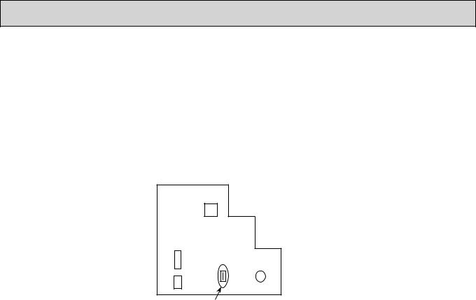
INDOOR UNIT DISPLAY SECTION
Operation Indicator lamp
The operation indicator at the right side of the indoor unit indicates the operation state. •The following indication applies regardless of shape of the indication.
Indication |
Operation state |
Room temperature |
|
The unit is operating to |
About 4°F (2°C) or more |
|
away from set tempera- |
|
|
reach the set temperature |
|
|
ture |
|
|
|
|
|
The room temperature is |
About 2 to 4°F (1 to 2°C) |
|
approaching the set tem- |
|
|
from set temperature |
|
|
perature |
|
|
|
|
|
Standby mode |
- |
|
(Only during multi system |
|
|
operation) |
|
Lighted
Blinking
Not lighted
OBH736 |
11 |
|
 Loading...