


SPLIT-TYPE, HEAT PUMP AIR CONDITIONERS
No. OB345
SERVICE MANUAL
Wireless type
Models
MSZ-A18YV - E1
MSZ-A24YV - E1
MSZ-A26YV - E1
Indication of model name
MSZ-A18YV - E1
MSZ-A24YV - E1
MSZ-A26YV - E1
CONTENTS
1.PART NAMES AND FUNCTIONS············
2.SPECIFICATION····················
3.NOISE CRITERIA CURVES ···············
4.OUTLINES AND DIMENSIONS ·············
5.WIRING DIAGRAM ··················
6.REFRIGERANT SYSTEM DIAGRAM ···········
7.SERVICE FUNCTIONS ·················
8.TROUBLESHOOTING·················
9.DISASSEMBLY INSTRUCTIONS ············
10.PARTS LIST······················
11.OPTIONAL PARTS ···················
NOTE: |
|
|
|
|
This service manual describes technical data of the indoor unit. |
|
|
||
•Refer to the service manual OB346 when MSZ-A18YV |
- E1 |
, MSZ-A24YV - E1 |
or MSZ-A26YV |
- E1 |
is connected with MUZ-A18YV - E1 , MUZ-A24YV - E1 |
or MUZ-A26YV - E1 . |
|
|
|
•Refer to the service manual OB319 when MSZ-A18YV |
- E1 |
, MSZ-A24YV - E1 |
or MSZ-A26YV |
- E1 |
is connected with MXZ-A26WV - E1 or MXZ-A32WV - E1 |
as multi system units. |
|
||
1 
 PART NAMES AND FUNCTIONS
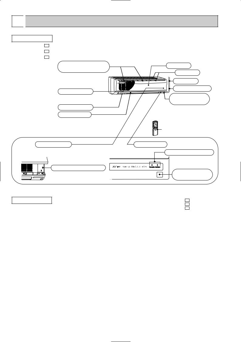
INDOOR UNIT
MSZ-A18YV - E1
MSZ-A24YV - E1
MSZ-A26YV - E1
Air cleaning filter (option) (White bellows type)
Catechin air filter
Vertical vanes
Horizontal vane
Grille
Air inlet
To Breaker
Power supply cord
Remote control receiving section
Remote controller
Operation section |
Display section |
(When the grille is opened) |
Operation indicator lamp |
|
Emergency operation switch
Remote control receiving section
ACCESSORIES
Indoor unit
|
|
MSZ-A18YV - E1 |
|
|
MSZ-A24YV - E1 |
|
|
MSZ-A26YV - E1 |
1 |
Installation plate |
1 |
|
|
|
2 |
Installation plate fixing screw 4 o 25 mm |
7 |
|
|
|
3 |
Remote controller holder |
1 |
|
|
|
4 |
Fixing screw for 3 o 3.5 o 1.6 mm (Black) |
2 |
|
|
|
5 |
Battery (AAA) for remote controller |
2 |
|
|
|
6 |
Wireless remote controller |
1 |
|
|
|
7 |
Felt tape (Used for left or left-rear piping) |
1 |
|
|
|
2
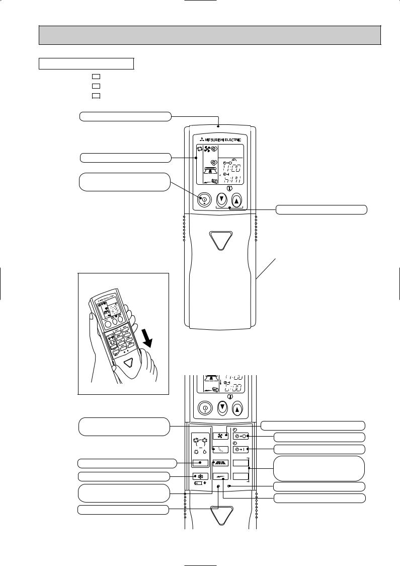
REMOTE CONTROLLER
MSZ-A18YV - E1
MSZ-A24YV - E1
MSZ-A26YV - E1
Signal transmitting section
Operation display section
OPERATE /STOP (ON /OFF)button
Open the front lid. |
VANE button (Horizontal vane button)
OPERATION SELECT button
ECONO COOL button
WIDE VANE button (Vertical vane button)
RESET button
|
|
PM |
|
|
AM |
ON/OFF |
TOO |
TOO |
|
WARM |
COOL |
TEMPERATURE buttons
Indication of remote controller model is on back.
CLOCK |
PM |
AM |
ON/OFF |
TOO |
TOO |
|
WARM |
COOL |
|
FAN |
STOP |
FAN SPEED CONTROL button |
|
|
||
I FEEL COOL |
|
|
OFF-TIMER button |
|
VANE |
START |
|
|
|
||
HEAT DRY |
|
|
ON-TIMER button |
|
|
|
|
MODE |
WIDE VANE |
HR. |
HR. button |
|
|
|
|
ECONO COOL |
LONG |
MIN. |
MIN. button |
|
|
|
(TIME SET button) |
|
RESET CLOCK |
|
CLOCK SET button |
|
|
|
|
|
|
|
LONG button |
3
2 |
|
SPECIFICATION |
|
|
|
|
|
|
|
|
|
|
|
|
|
|
|
•Refer to the service manual OB346 when MSZ-A18YV |
- E1 |
, MSZ-A24YV |
- E1 |
or MSZ-A26YV |
- E1 |
is connected with |
||
MUZ-A18YV - E1 , MUZ-A24YV - E1 or MUZ-A26YV - E1 . |
|
|
|
|
|
|||
•Refer to the service manual OB319 when MSZ-A18YV |
- E1 |
, MSZ-A24YV |
- E1 |
or MSZ-A26YV |
- E1 |
is connected with |
||
MXZ-A26WV - E1 or MXZ-A32WV - E1 as multi system units. |
|
|
|
|
||||
Indoor model
Function
|
|
Power supply |
|
|
Capacity Air flow(High/Med.w/Loww ) |
K /h |
|||
|
|
Power outlet |
A |
|
Electrical |
|
Running current 1 |
A |
|
data |
Power input 1 |
W |
||
Auxiliary heater |
A(kW) |
|||
Power factor 1 |
% |
|||
|
|
|||
|
|
Fan motor current 1 |
A |
|
|
motor |
Model |
|
|
Fan |
Winding |
" |
||
resistance(at 20:) |
||||
|
|
|
||
|
|
Dimensions WOHOD |
mm |
|
|
|
Weight |
kg |
|
|
|
Air direction |
|
|
|
|
Sound level(High/Med.w/Loww) |
dB |
|
Special |
remarks |
Fan speed(High/Med.w /Loww) |
rpm |
|
Fan speed regulator |
|
|||
Thermistor RT11(at 25:) |
k" |
|||
|
|
|
||
|
|
Thermistor RT12(at 25:) |
k" |
|
|
|
Thermistor RT13(at 25:) |
k" |
|
|
|
Remote controller model |
|
|
MSZ-A18YV - E1 |
MSZ-A24YV - E1 |
||||
Cooling |
Heating |
Cooling |
Heating |
||
|
Single phase |
Single phase |
|||
|
230V, 50Hz |
230V, 50Hz |
|||
|
852/690w/498w |
1,032/768w/522 w |
|
|
1,032/786w/522 w |
|
|
||||
|
10 |
10 |
|
||
|
0.30 |
0.34 |
|
||
|
60 |
69 |
|
||
|
— |
— |
|
||
|
87 |
87 |
|
||
|
0.30 |
0.34 |
|
||
|
RC4V32-AA |
RC4V40-AA |
|||
WHT-BLK 293 |
WHT-BLK 138.2 |
||||
BLK-RED 146 |
BLK-RED 159.0 |
||||
1,100O325O258 |
1,100O325O258 |
||||
|
16 |
16 |
|
||
|
5 |
5 |
|
||
|
43/38w/31w |
48/40w/32w |
|||
1,120/940w/720w |
1,310/1030w/750w |
|
|
1,310/1050w/750w |
|
|
|||||
|
3 |
3 |
|
||
|
10 |
10 |
|
||
|
10 |
10 |
|
||
|
10 |
10 |
|
||
|
KP0A |
KP0A |
|||
|
|
Indoor model |
|
|
MSZ-A26YV - E1 |
|
|
|
Function |
|
|
|
Cooling |
|
|
Power supply |
|
|
Single phase |
|
|
|
|
|
230V, 50Hz |
||
|
|
|
|
|
|
|
Capacity Air flow(High/Med.w/Loww ) |
K /h |
|
1,032/798w/564 w |
|||
|
|
Power outlet |
|
A |
|
10 |
Electrical |
|
Running current 1 |
|
A |
|
0.34 |
data |
Power input 1 |
|
W |
|
69 |
|
Auxiliary heater |
|
A(kW) |
|
— |
||
Power factor 1 |
|
% |
|
88 |
||
|
|
|
|
|||
|
|
Fan motor current 1 |
A |
|
0.34 |
|
|
motor |
Model |
|
|
|
RC4V40-AA |
Fan |
Winding |
|
" |
|
WHT-BLK 138.2 |
|
resistance(at 20:) |
|
|
BLK-RED 159.0 |
|||
|
|
|
|
|
||
|
|
Dimensions WOHOD |
mm |
|
1,100O325O258 |
|
|
|
Weight |
|
kg |
|
16 |
|
|
Air direction |
|
|
|
5 |
|
|
Sound level(High/Med.w/Low w) |
dB |
|
48/40w/33w |
|
Special |
remarks |
Fan speed(High/Med.w /Loww ) |
rpm |
|
1,310/1,060w/800w |
|
Fan speed regulator |
|
|
3 |
|||
Thermistor RT11(at 25:) |
k" |
|
10 |
|||
|
|
Thermistor RT12(at 25:) |
k" |
|
10 |
|
|
|
Thermistor RT13(at 25:) |
k" |
|
10 |
|
|
|
Remote controller model |
|
|
KP0A |
|
NOTE: Test conditions are based on ISO 5151. |
Wet-bulb temperature 19°C |
|||||
|
|
Cooling : Indoor |
Dry-bulb temperature 27°C |
|||
|
|
Outdoor Dry-bulb temperature 35°C |
Wet-bulb temperature(24°C) |
|||
|
|
Heating : Indoor |
Dry-bulb temperature 20°C |
Wet-bulb temperature 15.5°C |
||
|
|
Outdoor Dry-bulb temperature 7°C |
Wet-bulb temperature 6°C |
|||
|
|
Indoor-Outdoor piping length 5m |
|
|||
w Reference value
1 Measured under rated operating frequency.
4
Heating
1,032/816w/564w
1,310/1,080w/800 w

Specifications and rating conditions of main electric parts
INDOOR UNIT
Item |
Model |
MSZ-A18YV - E1 |
MSZ-A24YV - E1 |
|
MSZ-A26YV - E1 |
|
|
||||
|
|
|
|
|
|
|
|
|
|
|
|
Indoor fan capacitor |
(C11) |
|
2.5+ 440V |
|
|
Fuse |
(F11) |
|
250V 3.15A |
|
|
Vane motor |
(MV1/ MV2) |
|
MP20/MP20 |
|
|
Varistor |
(NR11) |
|
TNR10V511K410 |
|
|
Solid state relay |
(SR141) |
|
S201DH1N |
|
|
Terminal block |
(TB) |
|
3P |
|
|
|
|
|
|
|
|
Indoor fan motor thermal fuse |
145: |
|
|
|
|
|
|
|
|||
3 NOISE CRITERIA CURVES
MSZ-A18YV - E1
FAN SPEED SPL(dB(A)) |
LINE |
High 43
Test conditions,
Cooling : Dry-bulb temperature 27: Wet-bulb temperature 19: Heating : Dry-bulb temperature 20: Wet-bulb temperature 15.5:
BAR |
90 |
|
|
|
|
|
|
|
|
|
|
|
|
|
|
|
|
|
|
MICRO |
80 |
|
|
|
|
|
|
|
|
|
|
|
|
|
|
|
|
|
|
0.0002 |
70 |
|
|
|
|
|
|
|
NC-70 |
|
|
|
|
|
|
|
|
||
dB re |
60 |
|
|
|
|
|
|
|
|
LEVEL, |
|
|
|
|
|
|
|
|
|
|
|
|
|
|
|
|
|
NC-60 |
|
50 |
|
|
|
|
|
|
|
|
|
PRESSURE |
|
|
|
|
|
|
|
|
|
|
|
|
|
|
|
|
|
NC-50 |
|
40 |
|
|
|
|
|
|
|
|
|
|
|
|
|
|
|
|
|
NC-40 |
|
SOUND |
|
|
|
|
|
|
|
|
|
30 |
|
|
|
|
|
|
|
|
|
BAND |
|
|
|
|
|
|
|
|
NC-30 |
20 |
APPROXIMATE |
|
|
|
|
|
|
||
OCTAVE |
|
|
|
|
|
|
|||
THRESHOLD OF |
|
|
|
|
|
|
|||
|
|
|
|
|
|
|
|||
|
HEARING FOR |
|
|
|
|
|
NC-20 |
||
|
CONTINUOUS |
|
|
|
|
|
|||
|
|
|
|
|
|
|
|||
10 |
NOISE |
|
|
|
|
|
|
|
|
|
63 |
125 |
250 |
500 |
1000 |
2000 |
4000 |
8000 |
|
|
|
||||||||
BAND CENTER FREQUENCIES, Hz
MSZ-A24YV |
- E1 |
|
MSZ-A26YV |
- E1 |
|
|
FAN SPEED SPL(dB(A)) LINE |
|
|
High |
48 |
Test conditions,
Cooling : Dry-bulb temperature 27: Wet-bulb temperature 19: Heating : Dry-bulb temperature 20: Wet-bulb temperature 15.5:
BAR |
90 |
|
|
|
|
|
|
|
|
|
|
|
|
|
|
|
|
|
|
MICRO |
80 |
|
|
|
|
|
|
|
|
|
|
|
|
|
|
|
|
|
|
0.0002 |
70 |
|
|
|
|
|
|
|
NC-70 |
|
|
|
|
|
|
|
|
||
dB re |
60 |
|
|
|
|
|
|
|
|
LEVEL, |
|
|
|
|
|
|
|
|
|
|
|
|
|
|
|
|
|
NC-60 |
|
50 |
|
|
|
|
|
|
|
|
|
PRESSURE |
|
|
|
|
|
|
|
|
|
|
|
|
|
|
|
|
|
NC-50 |
|
40 |
|
|
|
|
|
|
|
|
|
|
|
|
|
|
|
|
|
NC-40 |
|
SOUND |
|
|
|
|
|
|
|
|
|
30 |
|
|
|
|
|
|
|
|
|
BAND |
|
|
|
|
|
|
|
|
NC-30 |
20 |
APPROXIMATE |
|
|
|
|
|
|
||
OCTAVE |
|
|
|
|
|
|
|||
THRESHOLD OF |
|
|
|
|
|
|
|||
|
|
|
|
|
|
|
|||
|
HEARING FOR |
|
|
|
|
|
NC-20 |
||
|
CONTINUOUS |
|
|
|
|
|
|||
|
|
|
|
|
|
|
|||
10 |
NOISE |
|
|
|
|
|
|
|
|
|
63 |
125 |
250 |
500 |
1000 |
2000 |
4000 |
8000 |
|
|
|
||||||||
BAND CENTER FREQUENCIES, Hz
INDOORUNIT
WALL
1m
0.8m
MICROPHONE
5
4 
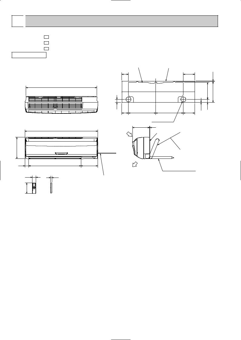
 OUTLINES AND DIMENSIONS
MSZ-A18YV - E1
MSZ-A24YV - E1
MSZ-A26YV - E1
INDOOR UNIT
1068
1100
325
56 |
791 |
58 |
19 |
162 |
|
Wireless remote controller
Unit: mm
Installation plate |
Indoor unit |
|
|
|
|
98 |
|
|
173 |
|
7.5 |
|
|
|
|
|
|
|
|
|
|
255.5 |
315 |
47 |
414.5 |
414.5 |
2.5 |
47 |
|
98 |
173 |
|
|
||
Wall hole [75
Air in
253
Air out
258 5
{Liquid line [ 6.35- 0.5m
Installation plate Gas line [ 12-0.43m Insulation [ 50 O.D
[ 32 I.D for MSZ-A18/A24YV
{Liquid line [ 9.52- 0.5m Gas line [ 12-0.43m Insulation [ 50 O.D
[ 32 I.D for MSZ-A26YV
Drain hose [16 (Connected part O.D)
Insulation [28
Power supply cord Lead to right 2.0m Lead to left 1.0m
6
5 |
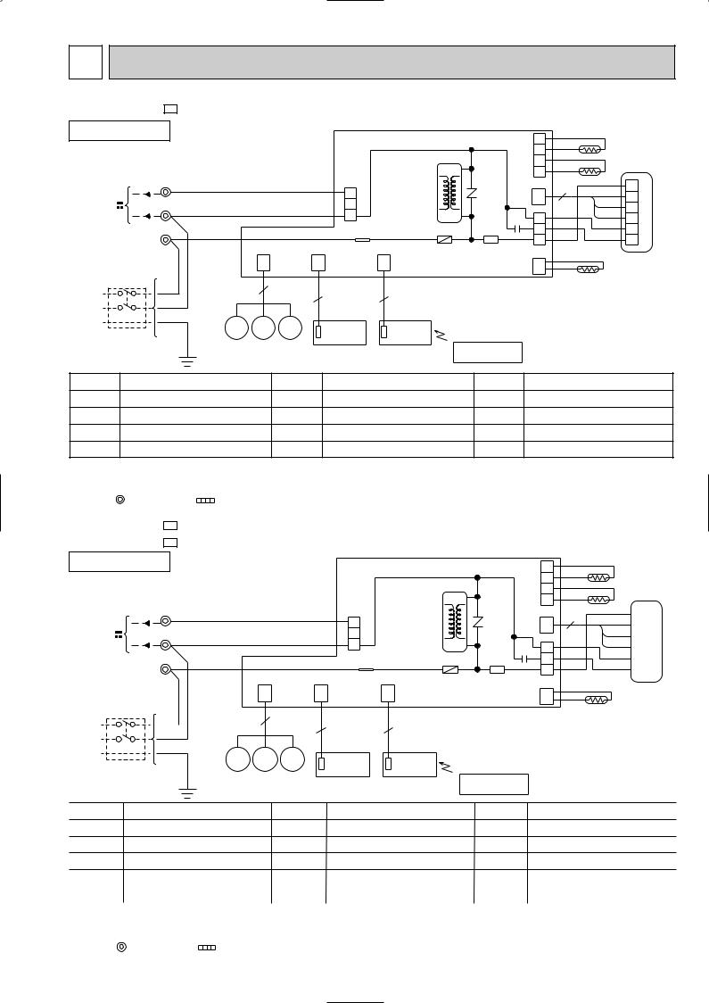
WIRING DIAGRAM |
|
|
|
|
|
||||||
MSZ-A18YV - E1 |
|
|
MODEL WIRING DIAGRAM |
|
|
|
|
|||||
INDOOR UNIT |
|
|
|
|
|
|
4 |
RT13 |
||||
|
|
|
|
|
|
|
|
|
|
|||
TO OUTDOOR |
|
|
|
|
|
|
|
|
3 |
|||
|
|
|
|
|
|
HIC1 |
|
|
|
|||
|
|
|
|
|
|
|
2 |
|
|
|||
UNIT |
|
|
|
|
|
|
|
|
|
RT12 |
||
|
|
|
|
|
|
|
|
|
1 |
|||
CONNECTING |
|
TB |
|
|
|
CN201 |
|
|
BLK |
|
||
3 |
RED |
|
|
|
CN112 3 |
1 |
||||||
|
|
|
|
|
3 |
|
GRY |
|||||
|
|
|
|
|
|
|
|
NR11 |
CN |
2 |
||
12V |
|
N |
|
|
|
2 |
|
|
121 |
YLW |
3 |
|
|
BLU |
|
|
|
|
|
||||||
|
|
|
|
|
|
1 |
TRANS |
C11 |
1 |
BRN |
4 MF |
|
|
|
|
|
|
|
|
||||||
|
|
|
|
|
|
|
WHT |
|||||
|
|
L |
|
BRN |
|
|
TAB12 |
F11 |
SR141 |
3 |
5 |
|
POWER |
|
|
|
4 |
RED |
6 |
||||||
|
|
|
|
|
|
|
|
|
||||
SUPPLY |
|
|
|
CN |
|
CN |
CN |
CN211 |
|
|
||
CORD |
|
|
|
|
|
CN |
RT11 |
|||||
~/N 230V |
|
|
|
151 |
|
102 |
101 ELECTRONIC CONTROL P.C. BOARD 111 |
|||||
50Hz |
BRN |
|
|
15 |
|
|
|
|
|
|
||
|
|
|
|
3 |
3 |
|
|
|
|
|||
|
|
BLU |
|
|
|
|
|
|
|
|||
PE |
|
|
GRN/YLW |
|
MV2 MV2 MV1 |
DISPLAY |
RECEIVER |
|
|
|
|
|
CIRCUIT |
|
|
|
|
|
|
||||||
|
|
|
|
P.C. BOARD |
P.C. BOARD |
|
|
|
|
|||
BREAKER |
|
|
|
|
|
|
|
|
|
|||
|
|
|
|
|
|
REMOTE |
|
|
|
|||
|
|
|
|
|
|
|
|
|
|
|
||
|
|
|
|
|
|
|
|
CONTROLLER |
|
|
|
|
SYMBOL |
|
|
NAME |
|
SYMBOL |
NAME |
SYMBOL |
|
NAME |
|
||
C11 |
INDOOR FAN CAPACITOR |
MV1 |
VANE MOTOR (HORIZONTAL) |
RT12 INDOOR COIL THERMISTOR (MAIN) |
||||||||
F11 |
FUSE (3.15A) |
|
|
MV2 |
VANE MOTOR (VERTICAL) |
RT13 |
INDOOR COIL THERMISTOR (SUB) |
|||||
HIC1 |
DC/DC CONVERTER |
NR11 |
VARISTOR |
SR141 |
SOLID STATE RELAY |
|||||||
MF |
INDOOR FAN MOTOR (INNER FUSE) |
RT11 |
ROOM TEMPERATURE THERMISTOR |
TB |
TERMINAL BLOCK |
|
||||||
NOTES: 1.About the outdoor side electric wiring refer to the outdoor unit electric wiring diagram for servicing. 2.Use copper conductors only. (For field wiring)
3.Symbols below indicate.
: Terminal block
MSZ-A24YV - E1 MSZ-A26YV - E1
INDOOR UNIT
TO OUTDOOR
UNIT
CONNECTING 3 TB
12V N
L
POWER
SUPPLY CORD ~/N 230V 50Hz
|
|
BRN |
|
|
BLU |
PE |
|
GRN/YLW |
|
CIRCUIT |
|
|
|
BREAKER
: Connector
MODELS WIRING DIAGRAM
|
|
|
|
4 |
RT13 |
|
|
|
|
3 |
|
|
|
HIC1 |
|
|
|
|
|
|
2 |
RT12 |
|
|
|
|
|
||
|
|
|
|
1 |
|
|
CN201 |
|
|
BLK |
|
RED |
|
CN112 |
|||
3 |
NR11 |
|
CN 3 |
GRY |
|
|
|
||||
BLU |
2 |
|
|
121 |
YLW |
1 |
TRANS |
C11 |
1 |
BRN MF |
|
|
|
F11 SR141 |
WHT |
||
BRN |
TAB12 |
|
3 |
||
|
RED |
||||
|
|
|
|
|
|
|
|
|
|
4 |
|
CN |
CN |
CN |
CN211 |
|
|
|
|
|
|||
151 |
102 |
101 ELECTRONIC CONTROL P.C. BOARD 111CN |
RT11 |
||
15 |
3 |
3 |
|
|
|
|
|
|
|
||
MV2 MV2 MV1 |
DISPLAY |
RECEIVER |
|
|
|
|
P.C. BOARD |
P.C. BOARD |
|
|
|
|
|
REMOTE |
|
|
|
CONTROLLER
SYMBOL |
NAME |
|
SYMBOL |
NAME |
SYMBOL |
NAME |
C11 |
INDOOR FAN CAPACITOR |
MV2 |
VANE MOTOR(VERTICAL) |
SR141 |
SOLID STATE RELAY |
|
F11 |
FUSE (3.15A) |
|
NR11 |
VARISTOR |
TB |
TERMINAL BLOCK |
HIC1 |
DC/DC CONVERTER |
RT11 |
ROOM TEMPERATURE THERMISTOR |
|
|
|
MF |
INDOOR FAN MOTOR (INNER PROTECTOR) |
RT12 |
INDOOR COIL THERMISTOR (MAIN) |
|
|
|
|
|
|
|
|
|
|
MV1 |
VANE MOTOR (HORIZONTAL) |
RT13 |
INDOOR COIL THERMISTOR (SUB) |
|
|
|
NOTES: 1.About the outdoor side electric wiring refer to the outdoor unit electric wiring diagram for servicing. |
|
|
||||
2.Use copper conductors only. (For field wiring) |
|
|
|
|||
3.Symbols below indicate. |
|
|
|
|
|
|
|
: Terminal block |
: Connector |
|
|
|
|
|
|
|
|
7 |
|
|
6 |
|
|
|
|
|
|
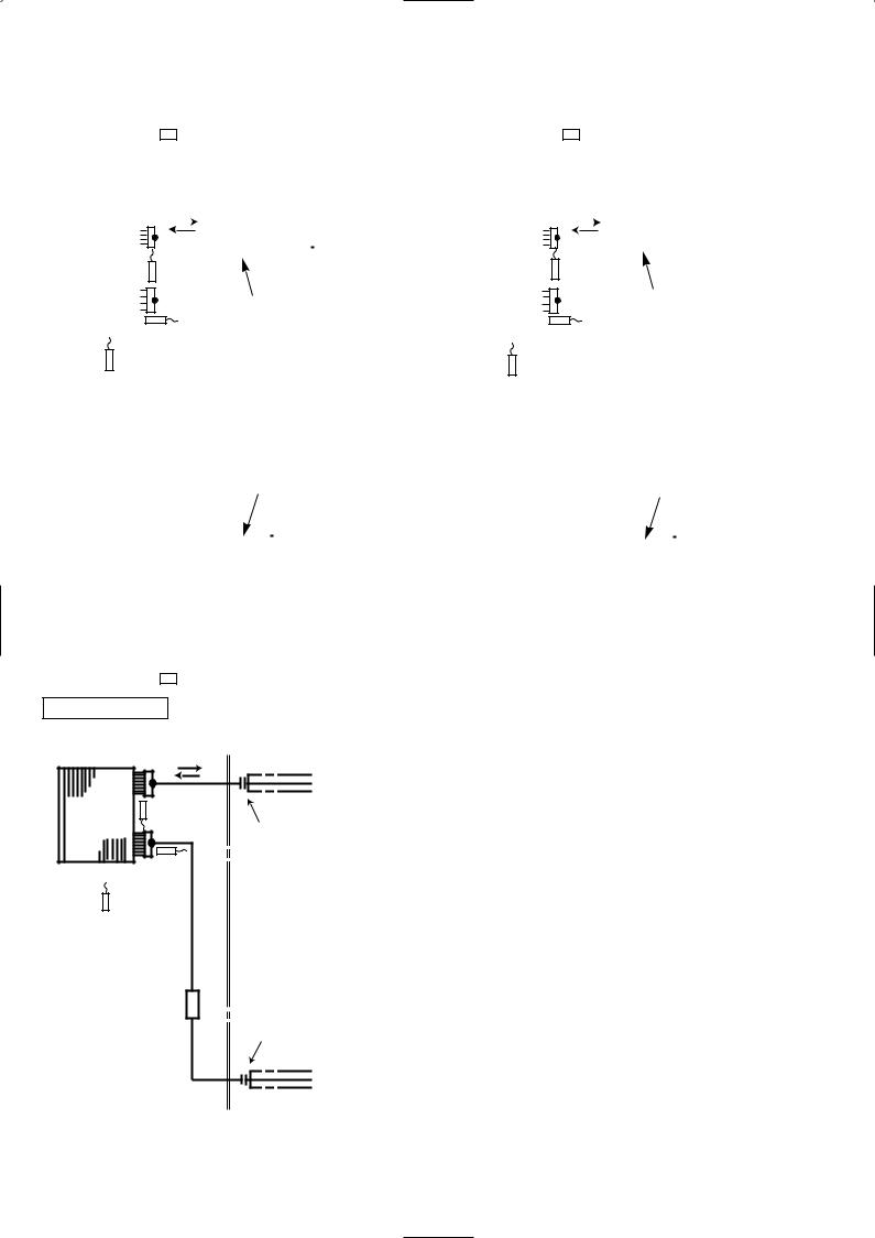
REFRIGERANT SYSTEM DIAGRAM |
|
|
|
|
|
|
|
|
|
|
|
|
|
|
|
|
|
|
|
|
|
|
||||||||||||||||||||||||||||||||||||||||||||||||
|
|
|
|
|
|
|
|
|
|
|
|
|
|
|
|
|
|
|
|
|
|
|
|
|
|
|
|
|
|
|
|
|
|
|
|
|
|
|
|
|
|
|
|
|
|
|
|
|
|
|
|
|
|
|
|
|
|
|
|
|
|
|
|
|
|
|
|
|
|
|
|
|
|
|
|
|
|
MSZ-A18YV - E1 |
MSZ-A24YV - E1 |
Unit:mm |
|||||||||||||||||||||||||||||||||||||||||||||||||||||||||||||||||||||||||||
|
|
|
|
|
|
|
|
|
|
|
|||||||||||||||||||||||||||||||||||||||||||||||||||||||||||||||||||
INDOOR UNIT |
|
|
|
|
|
|
|
|
|
|
|
|
|
|
|
|
|
|
|
|
|
|
INDOOR UNIT |
|
|||||||||||||||||||||||||||||||||||||||||||||||||||||
|
|
|
|
|
|
|
|
|
|
|
|
|
|
|
|
Refrigerant pipe [12.7 |
|
|
|
|
|
|
|
|
|
|
|
|
|
|
|
|
|
|
|
|
|
|
|
|
|
|
|
Refrigerant pipe |
[15.88 |
||||||||||||||||||||||||||||||||
|
|
|
|
|
|
|
|
|
|
|
|
|
|
|
|
(with heat insulator) |
|
|
|
|
|
|
|
|
|
|
|
|
|
|
|
|
|
|
|
|
|
|
|
|
|
|
|
(with heat insulator) |
|||||||||||||||||||||||||||||||||
|
|
|
|
|
|
|
|
|
|
|
|
|
|
|
|
|
|
|
|
|
|
|
|
|
|
|
|
|
|
|
|
|
|
|
|
|
|
|
|
|
|
|
|
|
|
|
|
|
|
|
|
|
|
|
|
|
|
|
|
|
|
|
|
|
|
|
|
|
|
|
|
|
|
|
|
|
|
|
|
|
|
|
|
|
|
|
|
|
Indoor coil |
|
|
|
|
|
|
|
|
|
|
|
|
|
|
|
|
|
|
|
|
|
|
|
|
|
|
|
|
|
|
|
|
|
|
|
|
|
|
|
|
Indoor coil |
|
|
|
|
|
|
|
|
|
|
|
|
|
|
|
|
|
||||||||
|
|
|
|
|
|
|
|
|
|
|
|
|
|
|
|
|
|
|
|
|
|
|
|
|
|
|
|
|
|
|
|
|
|
|
|
|
|
|
|
|
|
|
|
|
|
|
|
|
|
|
thermistor |
|
|
|
|
|
|
|
|
|
|
|
|
|
|
|
|
|
|||||||||
|
|
|
Indoor |
|
|
thermistor |
|
|
|
|
|
|
Indoor |
|
|
|
|
|
|||||||||||||||||||||||||||||||||||||||||||||||||||||||||||
|
|
|
heat |
|
|
RT12(main) |
|
|
|
|
|
|
|
|
|
|
|
|
|
|
|
|
|
|
|
|
|
heat |
|
|
|
RT12(main) |
|
|
|||||||||||||||||||||||||||||||||||||||||||
|
|
|
|
|
|
|
|
|
|
|
|
|
|
|
|
|
|
|
|
|
|
|
|
|
|
|
|
|
|
|
|
|
|
|
|
||||||||||||||||||||||||||||||||||||||||||
|
|
|
exchanger |
|
|
Distributor |
|
|
|
|
|
|
exchanger |
|
|
|
Distributor |
|
|
||||||||||||||||||||||||||||||||||||||||||||||||||||||||||
|
|
|
|
|
|
|
|
|
|
|
|
|
|
|
|
|
|
Flared connection |
|
|
|
|
|
|
|
|
|
|
|
|
|
|
|
|
|
|
|
|
|
|
|
|
|
|
|
|
|
Flared connection |
|||||||||||||||||||||||||||||
|
|
|
|
|
|
|
|
|
|
|
|
|
|
|
|
|
|
|
|
|
|
|
|
|
|
|
|
|
|
|
|
|
|
|
|
|
|
|
|
|
|
|
|
|
|
|
|
|
|
|
|
|
|
|
|
|
|
|
|
|
|
||||||||||||||||
|
|
|
|
|
|
|
|
|
|
|
|
|
|
|
|
|
|
|
|
|
|
|
|
|
|
|
|
|
|
|
|
|
|
|
|
|
|
|
|
|
|
|
|
|
|
|
|
|
|
|
|
|
|
|
|
|
|
|
|
|
|
|
|
|
|
|
|
|
|
|
|
|
|
|
|
|
|
|
|
|
|
|
|
|
|
|
Indoor coil |
|
|
|
|
|
|
|
|
|
|
|
|
|
|
|
|
|
|
|
|
|
|
|
|
|
|
|
|
|
|
|
|
|
|
|
|
Indoor coil |
|
|
|
|
|
|
|
|
|
|
|
|
|
|
|
||||||||||||||||
|
|
|
|
|
|
|
|
|
thermistor |
|
|
|
|
|
|
|
|
|
|
|
|
|
|
|
|
|
|
|
|
|
|
|
|
|
|
|
|
|
|
|
|
|
|
thermistor |
|
|
|
|
|
|
|
|
|
|
|
|
|
|
|
||||||||||||||||||
|
|
|
|
|
|
|
|
|
RT13(sub) |
|
|
|
|
|
|
|
|
|
|
|
|
|
|
|
|
|
|
|
|
|
|
|
|
|
|
|
|
|
|
|
|
|
|
RT13(sub) |
|
|
|
|
|
|
|
|
|
|
|
|
|
|
|
||||||||||||||||||
|
Room temperature |
|
|
|
|
|
|
|
|
|
|
|
|
|
|
|
|
|
|
|
Room temperature |
|
|
|
|
|
|
|
|
|
|
|
|
|
|
|
|
|
|
|
|||||||||||||||||||||||||||||||||||||
|
thermistor |
|
|
|
|
|
|
|
|
|
|
|
|
|
|
|
|
|
|
|
|
|
|
|
|
|
|
|
|
|
|
|
|
|
|
|
|
|
|
|
|
||||||||||||||||||||||||||||||||||||
|
|
|
|
|
|
|
|
|
|
|
|
|
|
|
|
|
|
|
|
|
|
|
|
|
|
thermistor |
|
|
|
|
|
|
|
|
|
|
|
|
|
|
|
|
|
|
|
|
|
|
|||||||||||||||||||||||||||||
|
RT11 |
|
|
|
|
|
|
|
|
|
|
|
|
|
|
|
|
|
|
|
|
|
|
|
|
|
|
|
|
|
|
|
|
|
|
|
|
|
|
|
|
|
|
|
|
|
|
|
|
||||||||||||||||||||||||||||
|
|
|
|
|
|
|
|
|
|
|
|
|
|
|
|
|
|
|
|
|
|
|
|
|
|
|
RT11 |
|
|
|
|
|
|
|
|
|
|
|
|
|
|
|
|
|
|
|
|
|
|
||||||||||||||||||||||||||||
|
|
|
|
|
|
|
|
|
|
|
|
|
|
|
|
|
|
|
|
|
|
|
|
|
|
|
|
|
|
|
|
|
|
|
|
|
|
|
|
|
|
|
|
|
|
|
|
|
|
|
|
|
|
|
|
|
|||||||||||||||||||||
|
|
|
|
|
|
|
|
|
|
|
|
|
|
|
|
|
|
Flared connection |
|
|
|
|
|
|
|
|
|
|
|
|
|
|
|
|
|
|
|
|
|
|
|
|
|
|
|
|
|
Flared connection |
|||||||||||||||||||||||||||||
|
|
|
|
|
|
|
|
|
|
|
|
|
|
|
|
|
|
|
|
|
|
|
|
|
|
|
|
|
|
|
|
|
|
|
|
|
|
|
|
|
|
|
|
|
|
|
|||||||||||||||||||||||||||||||
|
|
|
|
|
|
|
|
|
|
|
|
|
|
|
|
|
|
|
|
|
|
|
|
|
|
|
|
|
|
|
|
|
|
|
|
|
|
|
|
|
|
|
|
|
|
|
|||||||||||||||||||||||||||||||
|
|
|
|
|
|
|
|
|
|
|
|
|
|
|
|
|
|
|
|
|
|
|
|
|
|
|
|
|
|
|
|
|
|
|
|
|
|
|
|
|
|
|
|
|
|
|
|||||||||||||||||||||||||||||||
|
|
|
|
|
|
|
|
|
|
|
|
|
|
|
|
|
|
|
|
|
|
|
|
|
|
|
|
|
|
|
|
|
|
|
|
|
|
|
|
|
|
|
|
|
|
|
|||||||||||||||||||||||||||||||
|
|
|
|
|
|
|
|
|
|
|
|
|
|
|
|
|
|
|
|
|
|
|
|
|
|
|
|
|
|
|
|
|
|
|
|
|
|
|
|
|
|
|
|
|
|
|
|
|
|
|
|
|
|
|
|
|
|
|
|
|
|
|
|
|
|
|
|
|
|
|
|
|
|
|
|
|
|
|
|
|
|
|
|
|
|
|
|
|
|
|
|
|
|
|
|
|
|
|
|
|
|
|
|
|
|
|
|
|
|
|
|
|
|
|
|
|
|
|
|
|
|
|
|
|
|
|
|
|
|
|
|
|
|
|
|
|
|
|
|
|
|
|
|
|
|
|
|
|
|
|
|
|
|
|
|
|
|
|
|
|
|
|
|
|
|
|
|
|
|
|
|
|
|
|
|
|
|
|
|
|
|
|
|
|
|
|
|
|
|
|
|
|
|
|
|
|
|
|
|
|
|
|
|
|
|
|
|
|
|
|
|
|
|
|
|
|
|
|
|
|
|
|
|
|
|
|
|
|
|
|
|
|
|
Refrigerant pipe[6.35 |
Refrigerant pipe [6.35 |
(with heat insulator) |
(with heat insulator) |
MSZ-A26YV - E1 |
|
|
INDOOR UNIT |
|
|
|
|
Refrigerant pipe [15.88 |
|
|
(with heat insulator) |
Indoor |
Indoor coil |
|
heat |
thermistor |
|
exchanger |
RT12(main) |
Flared connection |
|
Indoor coil |
|
|
thermistor |
|
|
RT13(sub) |
|
Room temperature |
|
|
thermistor |
|
|
RT11 |
|
|
|
Strainer |
|
|
#50 |
|
|
|
Flared connection |
|
|
Refrigerant pipe [9.52 |
|
|
(with heat insulator) |
 Refrigerant flow in cooling
  Refrigerant flow in heating
8
 Loading...