


McIntosh Laboratory, Inc. 2 Chambers Street Binghamton, New York 13903-2699 Phone: 607-723-3512 www.mcintoshlabs.com
MC275
Tube Power Amplifier
Owner’s Manual
The lightning flash with arrowhead, within an equilateral triangle, is intended to alert the user to the presence of uninsulated “dangerous voltage” within the product’s enclosure that may be of sufficient magnitude to constitute a risk of electric shock to persons.
WARNING - TO REDUCE RISK OF FIRE OR ELECTRICAL SHOCK, DO NOT EXPOSE THIS EQUIPMENT TO RAIN OR MOISTURE.
IMPORTANT SAFETY INSTRUCTIONS!
PLEASE READ THEM BEFORE OPERATING THIS EQUIPMENT.
1.Read these instructions.
2.Keep these instructions.
3.Heed all warnings.
4.Follow all instructions.
5.Do not use this apparatus near water.
6.Clean only with a dry cloth.
7.Do not block any ventilation openings. Install in accordance with the manufacturer’s instructions.
8.Do not install near any heat sources such as radiators, heat registers, stoves, or other apparatus (including amplifiers) that produce heat.
9.Do not defeat the safety purpose of the polarized or grounding-type plug. A polarized plug has two blades with one wider than the other. A grounding type plug has two blades and a
NO USER-SERVICEABLE PARTS INSIDE. REFER SERVICING TO QUALIFIED PERSONNEL.
third grounding prong. The wide blade or the third prong are provided for your safety. If the provided plug does not fit into your outlet, consult an electrician for replacement of the obsolete outlet.
10.Protect the power cord from being walked on or pinched particularly at plugs, convenience receptacles, and the point where they exit from the apparatus.
11.Only use attachments/accessories specified by the manufacturer.
12.Use only with the cart, stand, tripod, bracket, or table specified by the manu-
facturer, or sold with the apparatus. When a cart is used, use caution when moving the cart/ apparatus combination to avoid injury from tip-over.
13.Unplug this apparatus during lightning storms or when unused for long periods of time.
14.Refer all servicing to qualified service personnel. Servicing is required when the apparatus has been damaged in any way, such as power-
The exclamation point within an equilateral triangle is intended to alert the user to the presence of important operating and maintenance (servicing) instructions in the literature accompanying the appliance.
To prevent the risk of electric shock, do not remove cover or back. No user-serviceable parts inside.
supply cord or plug is damaged, liquid has been spilled or objects have fallen into the apparatus, the apparatus has been exposed to rain or moisture, does not operate normally, or has been dropped.
15.Do not expose this equipment to dripping or splashing and ensure that no objects filled with liquids, such as vases, are placed on the equipment.
16.To completely disconnect this equipment from the a.c. mains, disconnect the power supply cord plug from the a.c. receptacle.
17.The mains plug of the power supply cord shall remain readily operable.
18.Do not expose batteries to excessive heat such as sunshine, fire or the like.
19.Connect mains power supply cord only to a mains socket outlet with a protective earthing connection.
2

IMPORTANT!
INSTRUCTIONS FOR REMOVAL OF FOAM INSERT OVER THE VACUUM TUBES PRIOR TO CONNECTING THE A.C. POWER SUPPLY CORD, START ON THE NEXT PAGE.
3
Unpacking the MC275
Caution: To prevent damage to the MC275 Tubes during shipping, there is a special foam insert surrounding the Tubes of the Power Amplifier.
The Foam Insert must be removed from the MC275 before connecting the AC Power Supply Cord to the power amplifier.
Failure to do so has the potential of a Fire Hazard, resulting in damage to the MC275 and the surrounding environment.
Follow these instructions for removal of the packing foam before connecting the AC Power Supply Cord to the MC275.
In order to remove the foam insert surrounding the tubes on the MC275, it is necessary to temporarily remove the Tube Cover. After the foam insert is removed, the Tube Cover is re-installed and should not be removed. The cover provides protection from the hazardous voltages inside the MC275. The MC275 has no
user serviceable parts, including the tubes. If repairs are needed they must be performed by an authorized McIntosh Service Agency.
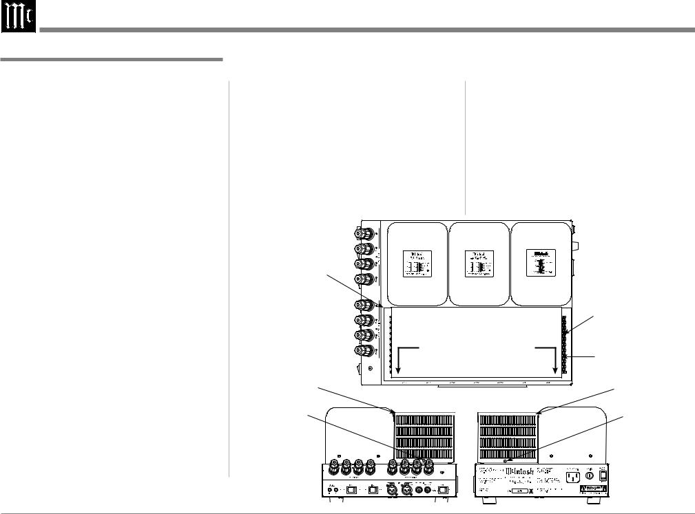
1.Orient the MC275 so the Front is facing you and remove the Warning Sheet. Refer to figure 1.
2.Using a Philips Head #2 screw driver, remove the Tube Cover Screw securing the Tube Cover to the chassis on each side of the MC275. Refer to figure 2. Carefully lift up and remove the Tube Cover from the MC275. Refer to figure 3.
3.Place the Tube Cover and the previously removed chassis screws in a safe location, as the Tube Cover will be reinstalled.
4.Carefully lift up and remove the Foam Insert from the MC275 exposing the Tubes. Refer to figures 4 and 5.
5.Carefully reinstall the previously removed Tube Cover using a Tube Cover Screw on each side of the MC275. Refer to figures 6, 7A, 7B and 8.
Note: Only use the chassis screws supplied with the MC275. If you can not find the chassis screws, contact the McIntosh Parts Department for replacements.
6.Save the Foam Insert and Warning Sheet with the MC275 Shipping Carton for possible future use.
Tube Cover
Tube Cover
Tube Cover
Screw
|
Remove Foam |
|
|
Insert located |
|
WARNING |
under the Tube |
|
Cover |
||
|
TO AVOID A FIRE HAZARD, THE FOAM INSERT |
|
OVER THE VACUUM TUBES MUST BE REMOVED |
Remove the |
SUPPLY CORD AND OPERATING THIS PRODUCT. |
|
PRIOR TO CONNECTING THE A.C. MAINS POWER |
|
REFER TO PAGE 3 IN THE MC275 OWNER’S |
Warning Sheet |
MANUAL FOR INSTRUCTIONS. |
|
Figure 1 |
Tube Cover |
|
Tube Cover
Screw
Handcrafted in USA with US and Imported Parts
Figure 2
4

Unpacking the MC275 and Ventilation
Figure 3 |
Foam Insert |
Figure 6 |
|
|
Figure 8
|
|
Ventilation |
|
|
Adequate ventilation extends the trouble free life of |
|
|
the MC275. Always allow air to flow through the |
|
|
ventilation holes on the bottom of the amplifier and a |
Figure 4 |
|
means for the warm air to escape at the top. Refer to |
|
figure 9. |
|
|
|
|
Figure 7A |
|
Allow at least 19 inches (48.3cm) above the top; 4 |
|
inches (10.2cm) for the Rear and Sides; allow 1/2 inch |
|
|
|
|
|
|
(1.3cm) below the Power Amplifier so the airflow is |
|
|
not obstucted. |
|
|
Warm Air |
Tube Cover |
|
Tube Cover |
Screw |
|
Screw |
Figure 5 |
|
|
|
|
Handcrafted in USA with US |
|
|
and Imported Parts |
|
Figure 7B |
Cool Air |
|
Figure 9 |
|
|
|
5

Thank You
Your decision to own this McIntosh MC275 Tube Power Amplifier ranks you at the very top among discriminating music listeners. You now have “The Best.” The McIntosh dedication to “Quality,” is assurance that you will receive many years of musical enjoyment from this unit.
Please take a short time to read the information in this manual. We want you to be as familiar as possible with all the features and functions of your new McIntosh.
Please Take A Moment
The serial number, purchase date and McIntosh Dealer name are important to you for possible insurance claim or future service. The spaces below have been provided for you to record that information:
Serial Number:________________________________
Purchase Date:_ _______________________________
Dealer Name:_ ________________________________
Technical Assistance
If at any time you have questions about your McIntosh product, contact your McIntosh Dealer who is familiar with your McIntosh equipment and any other brands that may be part of your system. If you or your Dealer wish additional help concerning a suspected problem, you can receive technical assistance for all McIntosh products at:
McIntosh Laboratory, Inc.
2 Chambers Street
Binghamton, New York 13903
Phone: 607-723-1545
Fax: 607-724-0549
Customer Service
If it is determined that your McIntosh product is in need of repair, you can return it to your Dealer. You can also return it to the McIntosh Laboratory Service Department. For assistance on factory repair return procedure, contact the McIntosh Service Department at: McIntosh Laboratory, Inc
2 Chambers Street Binghamton, New York 13903 Phone: 607-723-3515
Fax: 607-723-1917
Table of Contents |
|
Safety Instructions.................................................... |
2-3 |
Unpacking the MC275 and Ventilation.................... |
4-5 |
Thank You and Please Take a Moment....................... |
6 |
Technical Assistance and Customer Service............... |
6 |
Table of Contents......................................................... |
6 |
General Information.................................................... |
6 |
Connector Information................................................ |
7 |
Introduction................................................................. |
7 |
Performance Features.................................................. |
7 |
Dimensions.................................................................. |
8 |
Left Side Connections; Indicator and Switch: Right |
|
Side Connection, Fuse Holder and Switch.................. |
9 |
How to Connect for Stereo Operation....................... |
10 |
Connection Diagram (Separate Sheet)............. |
Mc1A |
How to Connect for Monaural Operation.................. |
12 |
Connection Diagram (Separate Sheet)............. |
Mc1B |
Right Side Switch, Left Side Switch and Indicators. 14 |
|
How to Operate.......................................................... |
15 |
Photos................................................................... |
16-17 |
Specifications............................................................ |
18 |
Packing Instruction................................................... |
19 |
Copyright 2012 © by McIntosh Laboratory, Inc.
General Information
1.For additional connection information, refer to the owner’s manual(s) for any component(s) connected to the MC275.
2.The MC275 mutes the speaker output for approximately fifteen seconds when first turned on.
3.For the best performance and safety it is important to always match the impedance of the loudspeaker to the Power Amplifier connections. Refer to pages
10 thru 13.
Note: The impedance of a Loudspeaker actually varies as the Loudspeaker reproduces different frequencies. As a result, the nominal impedance rating of the Loudspeaker (usually measured at a midrange frequency) might not always agree with the impedance of the Loudspeaker at low frequencies where the greatest amount of power is required. Contact the Loudspeaker Manufacturer for additional information about the actual impedance of the Loudspeaker before connecting
it to the McIntosh MC275.
4.The Ω is the symbol for the word ohms and refers to the impedance of the Output Terminals of the MC275.
5.When discarding the unit, comply with local rules
or regulations. Batteries should never be thrown away or incinerated but disposed of in accordance with the local regulations concerning battery disposal.
6. For additional information on the MC275 and other McIntosh Products please visit the McIntosh Web Site at www.mcintoshlabs.com.
6
 Loading...