


|
|
High Speed Drill |
Instruction Manual |
|
GB |
||
|
|
|
|
|
|
Perceuse à Haute Vitesse |
Manuel d’Instructions |
|
F |
||
|
|
|
|
|
|
Hochgeschwindigkeits- |
Betriebsanleitung |
|
D |
||
|
|
Bohrmaschine |
|
|
|
|
|
|
|
Trapano ad alta velocità |
Istruzioni d’Uso |
|
I |
||
|
|
|
|
|
|
Hoge-snelheid boormachine |
Gebruiksaanwijzing |
|
NL |
||
|
|
|
|
|
|
Taladro de Alta Velocidad |
Manual de Instrucciones |
|
E |
||
|
|
|
|
|
|
Furadeira de Alta Velocidade |
Manual de Instruções |
|
P |
||
|
|
|
|
|
|
Hurtigløbende boremaskine |
Brugsanvisning |
|
DK |
||
|
|
|
|
|
|
Τρυπάνι υψηλής ταχύτητας |
Οδηγίες χρήσεως |
|
GR |
||
|
|
|
|
|
|
Yüksek Hızlı Matkap |
Kullanma kılavuzu |
|
TR |
||
|
|
|
|
M6500
M6501

|
|
|
3 |
|
|
|
A |
|
1 |
|
B |
|
|
|
|
|
2 |
|
|
1 |
013476 |
2 |
013477 |
|
|
|
5 |
|
4 |
7 |
6 |
|
|
|
|
3 |
013475 |
4 |
013712 |
5 |
015473 |
|
2
ENGLISH (Original instructions)
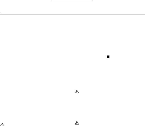
Explanation of general view
1 |
Switch trigger |
4 |
Chuck key |
7 Clamp screw |
2 |
Lock button |
5 |
Depth gauge |
|
3 |
Reversing switch lever |
6 |
Washer |
|
SPECIFICATIONS
|
|
Model |
|
|
M6500 |
|
M6501 |
|||
|
|
|
|
|
|
|
|
|
|
|
Capacities |
|
|
|
Steel |
|
6.5 mm |
|
|||
|
|
|
|
|
|
|
|
|||
|
|
|
Wood |
|
9 mm |
|
||||
|
|
|
|
|
|
|
||||
|
|
|
|
|
|
|
||||
|
No load speed (min–1) |
|
4,500 |
|
0 – 4,500 |
|||||
|
|
Overall length |
|
200 mm |
|
203 mm |
||||
|
|
|
|
|
|
|
|
|||
|
|
Net weight |
|
|
0.92 kg |
|
0.95 kg |
|||
|
|
|
|
|
|
|
|
|||
|
|
Safety class |
|
|
|
/II |
|
|||
|
|
|
|
|
||||||
• Due to our continuing program of research and |
7. Do not touch the drill bit |
or the workpiece |
||||||||
development, the specifications herein are subject to |
immediately after operation; they may be |
|||||||||
change without notice. |
|
|
|
|
extremely hot and could burn your skin. |
|||||
• Specifications may differ from country to country. |
|
8. Some material contains chemicals which may be |
||||||||
• Weight according to EPTA-Procedure 01/2003 |
|
toxic. Take caution to prevent dust inhalation |
||||||||
|
|
|
|
|
ENE032-1 |
and skin contact. Follow material supplier safety |
||||
|
|
|
|
|
data. |
|
||||
Intended use |
|
|
|
|
|
|
|
|||
|
|
|
|
|
|
SAVE THESE INSTRUCTIONS. |
||||
The tool is intended for drilling in wood, metal and plastic. |
||||||||||
|
|
|
|
|
ENF002-2 |
WARNING: |
|
|||
Power supply |
|
|
|
|
|
|
DO NOT let comfort or familiarity with product |
|||
The tool should be connected only to a power supply of |
(gained from repeated use) replace strict adherence |
|||||||||
the same voltage as indicated on the nameplate, and can |
to safety rules for the subject product. MISUSE or |
|||||||||
only be operated on single-phase AC supply. They are |
failure to follow the safety rules stated in this |
|||||||||
double-insulated and can, therefore, also be used from |
instruction manual may cause serious personal |
|||||||||
sockets without earth wire. |
|
|
|
|
injury. |
|
||||
|
|
|
|
|
GEA010-1 |
FUNCTIONAL DESCRIPTION |
|
|||
General Power Tool Safety Warnings |
|
|
||||||||
|
CAUTION: |
|
||||||||
WARNING |
Read |
all |
safety |
warnings and |
all |
|
||||
• Always be sure that the tool |
is switched off and |
|||||||||
instructions. |
Failure |
to |
follow |
the warnings |
and |
|||||
unplugged before adjusting or checking function on the |
||||||||||
instructions may result in |
electric |
shock, fire and/or |
||||||||
tool. |
|
|||||||||
serious injury. |
|
|
|
|
|
|
|
|||
|
|
|
|
|
|
|
|
|
||
Save all warnings and instructions for future reference.
GEB001-6
DRILL SAFETY WARNINGS
1.Use auxiliary handle(s), if supplied with the tool.
Loss of control can cause personal injury.
2.Hold power tool by insulated gripping surfaces, when performing an operation where the cutting accessory may contact hidden wiring or its own cord. Cutting accessory contacting a “live” wire may make exposed metal parts of the power tool “live” and could give the operator an electric shock.
3.Always be sure you have a firm footing.
Be sure no one is below when using the tool in high locations.
4.Hold the tool firmly.
5.Keep hands away from rotating parts.
6.Do not leave the tool running. Operate the tool only when hand-held.
Switch action (Fig. 1)
 CAUTION:
•Before plugging in the tool, always check to see the switch trigger actuates properly and returns to the “OFF” position when released.
•Switch can be locked in “ON” position for ease of operator comfort during extended use. Apply caution when locking tool in “ON” position and maintain firm grasp on tool.
For Model M6500
To start the tool, simply pull the switch trigger. Release the switch trigger to stop. For continuous operation, pull the switch trigger, push in the lock button and then release the switch trigger. To stop the tool from the locked position, pull the switch trigger fully, then release it.
3
For Model M6501
To start the tool, simply pull the switch trigger. Tool speed is increased by increasing pressure on the switch trigger. Release the switch trigger to stop. For continuous operation, pull the switch trigger, push in the lock button and then release the switch trigger. To stop the tool from the locked position, pull the switch trigger fully, then release it.
Reversing switch action (Fig. 2)
For Model M6501
This tool has a reversing switch to change the direction of rotation. Move the reversing switch lever to the D position (A side) for clockwise rotation or to the E position (B side) for counterclockwise rotation.
 CAUTION:
•Always check the direction of rotation before operation.
•Use the reversing switch only after the tool comes to a complete stop. Changing the direction of rotation before the tool stops may damage the tool.
ASSEMBLY
 CAUTION:
•Always be sure that the tool is switched off and unplugged before carrying out any work on the tool.
Installing or removing drill bit (Fig. 3)
 CAUTION:
•Always be sure that the tool is switched off and unplugged before installing or removing the bit.
To install the bit, place it in the chuck as far as it will go. Tighten the chuck by hand. Place the chuck key in each of the three holes and tighten clockwise. Be sure to tighten all three chuck holes evenly.
To remove the bit, turn the chuck key counterclockwise in just one hole, then loosen the chuck by hand.
Depth gauge (Fig. 4)
For tool with depth gauge
Install the depth gauge on the tool with the clamp screw and washer. Adjust the depth gauge to the desired depth and tighten the clamp screw.
OPERATION (Fig. 5)
 CAUTION:
•Always hold the tool only by the handle when performing an operation. Do not touch the metal part.
Drilling operation
Drilling in wood
When drilling in wood, the best results are obtained with wood drills equipped with a guide screw. The guide screw makes drilling easier by pulling the bit into the workpiece.
Drilling in metal
To prevent the bit from slipping when starting a hole, make an indentation with a center-punch and hammer at the point to be drilled. Place the point of the bit in the indentation and start drilling.
Use a cutting lubricant when drilling metals. The exceptions are iron and brass which should be drilled dry.
 CAUTION:
•Pressing excessively on the tool will not speed up the drilling. In fact, this excessive pressure will only serve to damage the tip of your bit, decrease the tool performance and shorten the service life of the tool.
•There is a tremendous force exerted on the tool/bit at the time of hole break through. Hold the tool firmly and exert care when the bit begins to break through the workpiece.
•Always secure small workpieces in a vise or similar hold-down device.
MAINTENANCE
 CAUTION:
•Always be sure that the tool is switched off and unplugged before carrying out any work on the tool.
•Never use gasoline, benzine, thinner, alcohol or the like. Discoloration, deformation or cracks may result.
To maintain product SAFETY and RELIABILITY, repairs, any other maintenance or adjustment should be performed by Makita Authorized Service Centers, always using Makita replacement parts.
ENG905-1
Noise
The typical A-weighted noise level determined according to EN60745:
Model M6500
Sound pressure level (LpA): 72 dB (A) Uncertainty (K): 3 dB (A)
The noise level under working may exceed 80 dB (A).
Model M6501
Sound pressure level (LpA): 70 dB (A) Uncertainty (K): 3 dB (A)
The noise level under working may exceed 80 dB (A).
Wear ear protection
ENG900-1
Vibration
The vibration total value (tri-axial vector sum) determined according to EN60745:
Model M6500
Work mode: drilling into metal Vibration emission (ah, D): 2.5 m/s2 Uncertainty (K): 1.5 m/s2
Model M6501
Work mode: drilling into metal Vibration emission (ah, D): 3.0 m/s2 Uncertainty (K): 1.5 m/s2
4
 Loading...