


GB |
Slide Compound Miter Saw |
INSTRUCTION MANUAL |
|
|
|
|
Skjutbar kapoch geringskombinationssåg |
BRUKSANVISNING |
S |
||
|
|
|
|
Skyvbar gjæringssag for kombinasjonssaging |
BRUKSANVISNING |
N |
||
|
|
|
|
Ristikelkkasaha |
KÄYTTÖOHJE |
FIN |
||
|
|
|
|
Slīdrāmja kombinētais leņķzāģis |
LIETOŠANAS INSTRUKCIJA |
LV |
||
|
|
|
|
Kombinuotas nuleidžiamas skersavimo |
NAUDOJIMO INSTRUKCIJA |
LT |
||
|
ir kampų suleidimo pjūklas |
|
|
|
|
|
|
|
|
Liuglõike eerungisaag |
KASUTUSJUHEND |
EE |
||
|
|
|
|
Торцовочная пила консольного типа |
РУКОВОДСТВО ПО ЭКСПЛУАТАЦИИ |
RUS |
||
|
|
|
LS0815F
LS0815FL
|
1 |
1 |
010228 |
|
1 |
4 |
010386 |
1 |
2 |
3 |
|
4 |
5 |
7 |
001800 |
1 |
2 |
10 |
010233 |
1 |
|
2 |
|
3 |
|
4 |
|
13 |
014307 |
1 |
1 |
2 |
011382 |
1
5 |
010387 |
|
1 |
|
2 |
8 |
014306 |
|
|
3 |
1 |
2 |
4 |
|
|
|
11 |
|
010234 |
1 |
|
2 |
|
3 |
|
14 |
014308 |
|
2 |
|
1 |
3 |
014305 |
|
1 |
|
2 |
6 |
014287 |
|
2 |
|
1 |
|
3 |
9 |
001540 |
|
1 |
12 |
014281 |
1
15 |
011352 |

|
|
1 |
|
3 |
|
|
2 |
|
|
|
|
|
|
|
|
|
|
|
4 |
16 |
|
|
|
010429 |
|
1 |
|
|
|
19 |
|
|
|
014270 |
|
|
|
|
1 |
22 |
|
|
|
014303 |
|
1 |
|
2 |
3 |
|
|
|
||
|
|
|
|
|
|
|
|
4 |
|
25 |
|
|
|
010392 |
2 |
|
|
1 |
|
|
|
|
|
|
3 |
|
|
|
|
28 |
|
|
|
014283 |
1 |
|
2 |
|
|
3 |
17 |
|
010388 |
|
1 |
|
20 |
|
014274 |
1 |
|
2 |
|
|
|
|
|
3 |
|
|
5 |
|
|
4 |
23 |
|
010390 |
1 |
|
3 |
|
6 |
|
|
|
|
2 |
4 |
5 |
26 |
|
014309 |
1 |
|
2 |
29 |
|
001549 |
|
3 |
|
|
1 |
18 |
014271 |
|
2 |
|
1 |
21 |
014282 |
1 |
|
|
5 |
|
4 |
|
3 |
|
2 |
24 |
010391 |
|
2 |
|
1 |
|
3 |
|
5 |
|
4 |
27 |
010560 |
|
1 |
|
2 |
30 |
014595 |

|
1 |
31 |
014647 |
34 |
014276 |
|
|
2 |
|
|
3 |
|
|
4 |
|
1 |
5 |
|
|
|
37 |
|
010404 |
3 |
|
1 |
|
|
|
2 |
|
|
40 |
|
014273 |
1 |
|
2 |
|
43 |
014299 |
1 |
2 |
3 |
|
4 |
|
5 |
|
32 |
014289 |
2 |
1 |
33 |
014284 |
1 |
2 |
3 |
35 |
|
001555 |
|
1 |
|
38 |
|
001563 |
|
1 |
2 |
|
|
|
41 |
|
014298 |
1
2
44 |
014295 |
1 |
(2) |
(1) |
|
(1) |
(2) |
(2) |
(4) |
2 |
(3) |
||
(1) |
|
|
(2) |
|
(1) |
(1) |
|
(2) |
36 |
|
001557 |
39 |
|
014292 |
|
|
1 |
|
3 |
2 |
|
|
|
42 |
|
014277 |
|
|
1 |
|
|
2 |
|
|
3 |
45 |
|
001819 |
4
1
2
3
46 |
014286 |
1 |
|
|
2 |
49 |
010256 |
1 |
2 |
|
47 |
48 |
007834 |
014296 |
|
5
ENGLISH LATVIEŠU
Contents |
|
|
Saturs |
|
|
|
SPECIFICATIONS |
........................................................ |
8 |
SPECIFIKĀCIJAS....................................................... |
|
|
64 |
General Power Tool Safety Warnings ........................... |
9 |
Vispārējie mehanizēto darbarīku drošības brīdinājumi65 |
||||
ADDITIONAL SAFETY RULES FOR TOOL.................. |
9 |
PAPILDUS DROŠĪBAS NOTEIKUMI DARBARĪKA |
||||
INSTALLATION........................................................... |
|
10 |
LIETOŠANAI .............................................................. |
|
|
65 |
FUNCTIONAL DESCRIPTION.................................... |
11 |
UZSTĀDĪŠANA .......................................................... |
|
|
66 |
|
ASSEMBLY ................................................................ |
|
13 |
FUNKCIJU APRAKSTS.............................................. |
|
|
67 |
OPERATION............................................................... |
|
15 |
MONTĀŽA.................................................................. |
|
|
70 |
MAINTENANCE ......................................................... |
|
19 |
EKSPLUATĀCIJA....................................................... |
|
|
71 |
OPTIONAL ACCESSORIES ....................................... |
20 |
APKOPE .................................................................... |
|
|
75 |
|
|
|
|
PAPILDU PIEDERUMI................................................ |
|
|
76 |
SVENSKA |
|
|
LIETUVIŲ KALBA |
|
|
|
Innehåll |
|
|
|
|
|
|
|
|
Turinys |
|
|
|
|
SPECIFIKATIONER.................................................... |
22 |
|
|
|
||
Allmänna säkerhetsvarningar för maskin .................... |
23 |
SPECIFIKACIJOS ...................................................... |
|
|
78 |
|
YTTERLIGARE |
SÄKERHETSANVISNINGAR |
FÖR |
Bendrieji perspėjimai darbui su elektriniais įrankiais |
...79 |
||
MASKINEN................................................................. |
|
23 |
PAPILDOMOS ĮRANKIO SAUGOS TAISYKLĖS ........ |
79 |
||
INSTALLATION........................................................... |
|
24 |
SUMONTAVIMAS....................................................... |
|
|
80 |
FUNKTIONSBESKRIVNING....................................... |
25 |
VEIKIMO APRAŠYMAS ............................................. |
|
|
81 |
|
MONTERING.............................................................. |
|
27 |
SURINKIMAS ............................................................. |
|
|
84 |
ANVÄNDNING............................................................ |
|
29 |
NAUDOJIMAS............................................................ |
|
|
85 |
UNDERHÅLL.............................................................. |
|
32 |
TECHNINĖ PRIEŽIŪRA ............................................. |
|
|
89 |
VALFRIA TILLBEHÖR ................................................ |
33 |
PASIRENKAMI PRIEDAI ............................................ |
|
|
90 |
|
NORSK |
|
|
EESTI |
|
|
|
Innhold |
|
|
Sisu |
|
|
|
TEKNISKE DATA........................................................ |
|
36 |
TEHNILISED ANDMED .............................................. |
|
|
92 |
Generelle advarsler angående sikkerhet |
for |
Üldised elektritööriistade ohutushoiatused.................. |
|
93 |
||
elektroverktøy ............................................................. |
|
37 |
TÄIENDAVAD TÖÖRIISTA OHUTUSNORMID ........... |
93 |
||
YTTERLIGERE |
SIKKERHETSREGLER |
FOR |
PAIGALDAMINE......................................................... |
|
|
94 |
MASKINEN................................................................. |
|
37 |
FUNKTSIONAALNE KIRJELDUS............................... |
|
95 |
|
MONTERING.............................................................. |
|
38 |
KOKKUPANEK........................................................... |
|
|
98 |
FUNKSJONSBESKRIVELSE ..................................... |
39 |
TÖÖRIISTA KASUTAMINE......................................... |
|
|
99 |
|
MONTERING.............................................................. |
|
41 |
HOOLDUS................................................................ |
|
|
103 |
BRUK ......................................................................... |
|
43 |
VALIKULISED TARVIKUD ........................................ |
|
|
104 |
VEDLIKEHOLD .......................................................... |
|
47 |
|
|
|
|
VALGFRITT TILBEHØR ............................................. |
48 |
РУССКИЙ ЯЗЫК |
|
|
|
|
|
|
|
|
|
|
|
SUOMI |
|
|
Содержание |
|
|
|
|
|
ТЕХНИЧЕСКИЕ ХАРАКТЕРИСТИКИ |
|
106 |
||
Sisällys |
|
|
|
|||
|
|
Общие рекомендации по технике безопасности для |
||||
TEKNISET TIEDOT .................................................... |
50 |
электроинструментов ............................................. |
|
|
107 |
|
Sähkötyökalujen käyttöä koskevat varoitukset............ |
51 |
ДОПОЛНИТЕЛЬНЫЕ |
ПРАВИЛА |
ТЕХНИКИ |
||
LISÄÄ TURVAOHJEITA KONEELLE .......................... |
51 |
БЕЗОПАСНОСТИ ДЛЯ ИНСТРУМЕНТА................ |
|
107 |
||
ASENNUS .................................................................. |
|
52 |
УСТАНОВКА............................................................ |
|
|
109 |
TOIMINTOJEN KUVAUS ............................................ |
53 |
ОПИСАНИЕ ФУНКЦИОНИРОВАНИЯ.................... |
|
109 |
||
KOKOONPANO.......................................................... |
|
55 |
МОНТАЖ................................................................. |
|
|
113 |
TYÖSKENTELY.......................................................... |
|
57 |
ЭКСПЛУАТАЦИЯ..................................................... |
|
|
115 |
KUNNOSSAPITO ....................................................... |
|
61 |
ТЕХОБСЛУЖИВАНИЕ ............................................ |
|
|
119 |
LISÄVARUSTEET....................................................... |
|
62 |
ДОПОЛНИТЕЛЬНЫЕ ПРИНАДЛЕЖНОСТИ |
.......... |
120 |
|
6
ENGLISH (Original instructions)
Explanation of general view
1-1. Stopper pin |
20-1. Switch for light |
32-4. Screw |
2-1. Bolts |
21-1. Socket wrench with hex wrench |
32-5. Guide fence |
3-1. Adjusting bolt |
on its other end |
33-1. Holder |
4-1. Blade guard |
21-2. Wrench holder |
33-2. Screw |
5-1. Blade guard |
22-1. Stopper pin |
35-1. 52/38 type crown molding |
6-1. Kerf board |
23-1. Socket wrench |
35-2. 45 type crown molding |
6-2. Screw |
23-2. Blade case |
35-3. 45 type cove molding |
7-1. Saw blade |
23-3. Center cover |
36-1. Inside corner |
7-2. Blade teeth |
23-4. Hex bolt |
36-2. Outside corner |
7-3. Kerf board |
23-5. Blade guard |
37-1. Guide fence |
7-4. Left bevel cut |
24-1. Blade case |
37-2. Vise |
7-5. Straight cut |
24-2. Socket wrench |
37-3. Spacer block |
8-1. Adjusting bolt |
24-3. Hex bolt |
37-4. Aluminum extrusion |
8-2. Turn base |
24-4. Arrow |
37-5. Spacer block |
9-1. Top surface of turn base |
24-5. Shaft lock |
38-1. Cut grooves with blade |
9-2. Periphery of blade |
25-1. Blade case |
40-1. Guide fence |
9-3. Guide fence |
25-2. Arrow |
40-2. Hex bolts |
10-1. Stopper arm |
25-3. Arrow |
40-3. Grip |
10-2. Adjusting screw |
25-4. Saw blade |
41-1. Guide fence |
11-1. Miter scale |
26-1. Hex bolt (left-handed) |
41-2. Triangular rule |
11-2. Pointer |
26-2. Outer flange |
42-1. Screw |
11-3. Lock lever |
26-3. Saw blade |
42-2. Pointer |
11-4. Grip |
26-4. Ring |
42-3. Miter scale |
12-1. Lever |
26-5. Inner flange |
43-1. Lever |
13-1. Lever |
26-6. Spindle |
43-2. Arm |
13-2. Arm |
27-1. Socket wrench |
44-1. 0 adjusting bolt |
13-3. Pointer |
27-2. Blade case |
44-2. Left 45 bevel angle adjusting |
13-4. Bevel scale |
27-3. Center cover |
bolt |
14-1. Pointer |
27-4. Hex bolt |
45-1. Triangular rule |
14-2. Release button |
27-5. Blade guard |
45-2. Saw blade |
14-3. Bevel scale |
28-1. Dust nozzle |
45-3. Top surface of turn table |
15-1. Locking screw |
28-2. Dust bag |
46-1. Screw |
16-1. Lock-off button |
28-3. Fastener |
46-2. Pointer |
16-2. Lever |
29-1. Support |
46-3. Bevel scale |
16-3. Switch trigger |
29-2. Turn base |
47-1. Right 5 bevel angle adjusting |
16-4. Hole for padlock |
30-1. Sliding fence |
bolt |
17-1. Lock-off button |
30-2. Clamping screw |
47-2. Left 45 bevel angle adjusting |
17-2. Switch trigger |
31-1. Sliding fence |
bolt |
17-3. Hole for padlock |
32-1. Vise arm |
49-1. Screwdriver |
18-1. Switch for laser |
32-2. Vise knob |
49-2. Brush holder cap |
19-1. Light |
32-3. Vise rod |
|
|
|
|
7

SPECIFICATIONS
Model |
|
|
|
LS0815F / LS0815FL |
|
Blade diameter |
|
|
|
|
216 mm |
Blade thickness |
|
|
|
|
1.5 - 2.5 mm |
Hole diameter |
|
|
|
|
|
- For all countries other than European countries |
|
|
|
|
25.4 mm |
- For European countries |
|
|
|
|
30 mm |
Max. Miter angle |
|
|
|
|
Left 50° Right 60° |
Max. Bevel angle |
|
|
|
|
Left 48° Right 5° |
Max. Cutting capacities (H x W) with 216 mm in diameter |
|
|
|
|
|
Miter angle |
|
|
Bevel angle |
|
|
45° (left) |
|
5° (right) |
|
0° |
|
|
|
|
|||
0° |
50 mm x 305 mm |
|
60 mm x 305 mm |
|
65 mm x 305 mm |
45° |
50 mm x 215 mm |
|
- |
|
65 mm x 215 mm |
60° (right) |
- |
|
- |
|
65 mm x 150 mm |
Rated voltage |
|
|
|
220 - 240 V, 50 - 60 Hz |
|
Rated input |
|
|
|
1,400 w, S6 40% 5 min |
|
No load speed (min-1) |
|
|
|
5,000 |
|
Laser Type (LS0815FL only) |
|
Red Laser 650 nm, |
1mW ( Laser Class 2 ) |
||
Dimensions (L x W x H) |
|
|
755 mm x 450 mm x 488 mm |
||
Net weight |
For all countries other than European countries•••14.1 kg |
||||
|
|
|
For European countries•••LS0815F 14.1 kg |
||
|
|
|
|
••• LS0815FL 14.2 kg |
|
Safety class |
|
|
|
|
/II |
•Due to our continuing program of research and development, the specifications herein are subject to change without notice.
•Specifications may differ from country to country.
•Weight according to EPTA-Procedure 01/2003
END223-4
Symbols
The following show the symbols used for the equipment. Be sure that you understand their meaning before use.
Read instruction manual.
DOUBLE INSULATION
To avoid injury from flying debris, keep holding the saw head down, after making cuts, until the blade has come to a complete stop.
When performing slide cut, first pull carriage fully and press down handle, then push carriage toward the guide fence.
Do not place hand or fingers close to the blade.
Adjust sliding fences clear of blade and blade guard properly.
LASER RADIATION: Do not stare into beam. Direct laser beam may injure your eyes.
Only for EU countries
Do not dispose of electric equipment together with household waste material!
In observance of the European Directive, on Waste Electric and Electronic Equipment and its implementation in accordance with national law, electric equipment that have reached the end of their life must be collected separately and returned to an environmentally compatible recycling facility.
ENE006-1
Intended use
The tool is intended for accurate straight and miter cutting in wood. With appropriate saw blades, aluminum can also be sawed.
ENF002-2
Power supply
The tool should be connected only to a power supply of the same voltage as indicated on the nameplate, and can only be operated on single-phase AC supply. They are double-insulated and can, therefore, also be used from sockets without earth wire.
8

ENG905-1
Noise
The typical A-weighted noise level determined according to EN61029:
Sound pressure level (LpA) : 87 dB (A)
Sound power level (LWA) : 110 dB (A)
Uncertainty (K) : 3 dB (A)
Wear ear protection
ENG900-1
Vibration
The vibration total value (tri-axial vector sum) determined according to EN61029:
Vibration emission (ah) : 2.5 m/s2 or less Uncertainty (K) : 1.5 m/s2
ENG901-1
•The declared vibration emission value has been measured in accordance with the standard test method and may be used for comparing one tool with another.
•The declared vibration emission value may also be used in a preliminary assessment of exposure.
 WARNING:
•The vibration emission during actual use of the power tool can differ from the declared emission value depending on the ways in which the tool is used.
•Be sure to identify safety measures to protect the operator that are based on an estimation of exposure in the actual conditions of use (taking account of all parts of the operating cycle such as the times when the tool is switched off and when it is running idle in addition to the trigger time).
ENH103-1
For European countries only
EC Declaration of Conformity
Makita declares that the following Machine(s):
Designation of Machine:
Slide Compound Miter Saw Model No./ Type:
LS0815F, LS0815FL
Conforms to the following European Directives:
2006/42/EC, 2006/95/EC, 2006/108/EC, 2006/65/EC
They are manufactured in accordance with the following Standard or standardized documents:
EN61029, EN 55014-1, EN 55014-2, EN 61000-3-2, EN 61000-3-3
The Technical file in accordance with 2006/42/EC is available from:
Makita, Jan-Baptist Vinkstraat 2, 3070, Belgium
20.12.2013
000331
Yasushi Fukaya
Director
Makita, Jan-Baptist Vinkstraat 2, 3070, Belgium
GEA010-1
General Power Tool Safety Warnings
 WARNING Read all safety warnings and all instructions. Failure to follow the warnings and instructions may result in electric shock, fire and/or serious injury.
Save all warnings and instructions for
future reference.
ENB034-7
ADDITIONAL SAFETY RULES FOR TOOL
1.Wear eye protection.
2.Keep hands out of path of saw blade. Avoid contact with any coasting blade. It can still cause severe injury.
3.Do not operate saw without guards in place. Check blade guard for proper closing before each use. Do not operate saw if blade guard does not move freely and close instantly. Never clamp or tie the blade guard into the open position.
4.Do not perform any operation freehand. The workpiece must be secured firmly against the turn base and guide fence with the vise during all operations. Never use your hand to secure the workpiece.
5.Never reach around saw blade.
6.Turn off tool and wait for saw blade to stop before moving workpiece or changing settings.
7.Unplug tool before changing blade or servicing.
8.Always secure all moving portions before carrying the tool.
9.Stopper pin which locks the cutter head down is for carrying and storage purposes only and not for any cutting operations.
10.Do not use the tool in the presence of flammable liquids or gases. The electrical operation of the tool could create an explosion and fire when exposed to flammable liquids or gases.
11.Check the blade carefully for cracks or damage before operation.
Replace cracked or damaged blade immediately.
9
12.Use only flanges specified for this tool.
13.Be careful not to damage the arbor, flanges (especially the installing surface) or bolt. Damage to these parts could result in blade breakage.
and work with approved safety equipment, such as those dust masks that are specially designed to filter out microscopic particles.
34.To reduce the emitted noise, always be sure that the blade is sharp and clean.
14.Make sure that the turn base is properly 35. The operator is adequately trained in the use,
secured so it will not move during operation. |
adjustment and operation of the machine. |
15.For your safety, remove the chips, small 36. Use correctly sharpened saw blades. Observe
pieces, etc. from the table top before operation.
16.Avoid cutting nails. Inspect for and remove all nails from the workpiece before operation.
17.Make sure the shaft lock is released before the switch is turned on.
18.Be sure that the blade does not contact the turn base in the lowest position.
19.Hold the handle firmly. Be aware that the saw moves up or down slightly during start-up and stopping.
the maximum speed marked on the saw blade.
37.Refrain from removing any cut-offs or other parts of the workpiece from the cutting area whilst the tool is running and the saw head is not in the rest position.
38.Use only saw blades recommended by the manufacturer which conform to EN847-1.
39.Wear gloves for handling saw blade (saw blades shall be carried in a holder wherever practicable) and rough material.
20.Make sure the blade is not contacting the 40. Keep the floor area free of loose material e.g.
workpiece before the switch is turned on.
21.Before using the tool on an actual workpiece, let it run for a while. Watch for vibration or wobbling that could indicate poor installation or a poorly balanced blade.
22.Wait until the blade attains full speed before cutting.
23.Stop operation immediately if you notice anything abnormal.
24.Do not attempt to lock the trigger in the on position.
25.Be alert at all times, especially during repetitive, monotonous operations. Do not be lulled into a false sense of security. Blades are extremely unforgiving.
26.Always use accessories recommended in this manual. Use of improper accessories such as abrasive wheels may cause an injury.
27.Do not use the saw to cut other than wood, aluminum or similar materials.
28.Connect miter saws to a dust collecting device when sawing.
29.Select saw blades in relation to the material to be cut.
30.Take care when slotting.
31.Replace the kerf board when worn.
32.Do not use saw blades manufactured from high speed steel.
33.Some dust created from operation contains chemicals known to cause cancer, birth defects or other reproductive harm. Some examples of these chemicals are:
•lead from lead-based-painted material and,
•arsenic and chromium from chemicallytreated lumber.
Your risk from these exposures varies, depending on how often you do this type of work. To reduce your exposure to these chemicals: work in a well ventilated area
chips and cut-offs.
41.When fitted with laser, no exchange with different type of laser is permitted. Repairs shall only be carried out correctly.
SAVE THESE INSTRUCTIONS.
INSTALLATION
Bench mounting
Fig.1
When the tool is shipped, the handle is locked in the lowered position by the stopper pin. Release the stopper pin by simultaneously applying a slight downward pressure on the handle and pulling the stopper pin.
 WARNING:
•Ensure that the tool will not move on the supporting surface. Movement of the miter saw on the supporting surface while cutting may result in loss of control and serious personal injury.
Fig.2
This tool should be bolted with four bolts to a level and stable surface using the bolt holes provided in the tool's base. This will help prevent tipping and possible injury.
Fig.3
Turn the adjusting bolt clockwise or counterclockwise so that it comes into a contact with the tool surface to keep the tool stable.
10
FUNCTIONAL DESCRIPTION
 WARNING:
•Always be sure that the tool is switched off and unplugged before adjusting or checking function on the tool. Failure to switch off and unplug the tool may result in serious personal injury from accidental start-up.
Blade guard
Fig.4
When lowering the handle, the blade guard rises automatically. The blade guard returns to its original position when the cut is completed and the handle is raised.
WARNING:
•Never defeat or remove the blade guard or the spring which attaches to the guard. An exposed blade as a result of defeated guarding may result
in serious personal injury during operation.
In the interest of your personal safety, always maintain the blade guard in good condition. Any irregular operation of the blade guard should be corrected immediately. Check to assure spring loaded return action of guard.
WARNING:
•Never use the tool if the blade guard or spring are damaged, faulty or removed. Operation of the tool with a damaged, faulty or removed guard may result in serious personal injury.
If the see-through blade guard becomes dirty, or sawdust adheres to it in such a way that the blade and/or workpiece is no longer easily visible, unplug the saw and clean the guard carefully with a damp cloth. Do not use solvents or any petroleum-based cleaners on the plastic guard because this may cause damage to the guard.
If the blade guard becomes dirty and needs to be cleaned for proper operation follow the steps below: With the tool switched off and unplugged, use the supplied socket wrench to loosen the hex bolt holding the center cover. Loosen the hex bolt by turning it counterclockwise and raise the blade guard and center cover.
Fig.5
With the blade guard so positioned, cleaning can be more completely and efficiently accomplished. When cleaning is complete reverse procedure above and secure bolt. Do not remove spring holding blade guard. If guard becomes damaged through age or UV light exposure, contact a Makita service center for a new guard. DO NOT DEFEAT OR REMOVE GUARD.
Positioning kerf board
Fig.6
Fig.7
This tool is provided with the kerf boards in the turn base to minimize tearing on the exit side of a cut. The kerf boards are factory adjusted so that the saw blade does not contact the kerf boards. Before use, adjust the kerf boards as follows:
First, unplug the tool. Loosen all the screws (3 each on left and right) securing the kerf boards. Re-tighten them only to the extent that the kerf boards can still be easily moved by hand. Lower the handle fully and push in the stopper pin to lock the handle in the lowered position. Loosen the screw which secures the slide poles. Pull the carriage toward you fully. Adjust the kerf boards so that the kerf boards just contact the sides of the blade teeth. Tighten the front screws (do not tighten firmly). Push the carriage toward the guide fence fully and adjust the kerf boards so that the kerf boards just contact the sides of blade teeth. Tighten the rear screws (do not tighten firmly).
After adjusting the kerf boards, release the stopper pin and raise the handle. Then tighten all the screws securely.
NOTICE:
•After setting the bevel angle ensure that the kerf boards are adjusted properly. Correct adjustment of the kerf boards will help provide proper support of the workpiece minimizing workpiece tear out.
Maintaining maximum cutting capacity
This tool is factory adjusted to provide the maximum cutting capacity for a 216 mm saw blade.
Unplug the tool before any adjustment is attempted. When installing a new blade, always check the lower limit position of the blade and if necessary, adjust it as follows:
Fig.8
Fig.9
First, unplug the tool. Push the carriage toward the guide fence fully and lower the handle completely. Use the hex. wrench to turn the adjusting bolt until the periphery of the blade extends slightly below the top surface of the turn base at the point where the front face of the guide fence meets the top surface of the turn base.
With the tool unplugged, rotate the blade by hand while holding the handle all the way down to be sure that the blade does not contact any part of the lower base. Readjust slightly, if necessary.
 WARNING:
•After installing a new blade and with the tool unplugged, always be sure that the blade does not contact any part of the lower base when the handle is lowered completely. If a blade makes contact with the base it may cause kickback and result in serious personal injury.
11

Stopper arm
Fig.10
The lower limit position of the blade can be easily adjusted with the stopper arm. To adjust it, move the stopper arm in the direction of the arrow as shown in the figure. Adjust the adjusting screw so that the blade stops at the desired position when lowering the handle fully.
Adjusting the miter angle
Fig.11
Loosen the grip by turning counterclockwise. Turn the turn base while pressing down the lock lever. When you have moved the grip to the position where the pointer points to the desired angle on the miter scale, securely tighten the grip clockwise.
 CAUTION:
•After changing the miter angle, always secure the turn base by tightening the grip firmly.
NOTICE:
•When turning the turn base, be sure to raise the handle fully.
Adjusting the bevel angle
Fig.12
To adjust the bevel angle, loosen the lever at the rear of the tool counterclockwise. Unlock the arm by pushing the handle somewhat strongly in the direction that you intend to tilt the saw blade.
NOTE:
•Lever can be adjusted to a different lever angle by removing the screw holding the lever and securing the lever at a desired angle.
Fig.13
Tilt the saw blade until the pointer points to the desired angle on the bevel scale. Then tighten the lever clockwise firmly to secure the arm.
Fig.14
To tilt the saw blade to right 5 or left 48 : set the saw blade to 0 for right 5 , or 45 for left 48 . Then slightly tilt the saw blade to the opposite side. Push the release button and tilt the saw blade to the desired position. Tighten the lever to secure the arm.
 CAUTION:
•After changing the bevel angle, always secure the
arm by tightening the lever clockwise.
NOTICE:
•When tilting the saw blade be sure the handle is fully raised.
•When changing bevel angles, be sure to position the kerf boards appropriately as explained in the "Positioning kerf boards" section.
Slide lock adjustment
Fig.15
To lock the slide pole, turn the locking screw clockwise.
Switch action
For European countries
Fig.16
To prevent the switch trigger from being accidentally pulled, a lock-off button is provided. To start the tool, push the lever to the left, press in the lock-off button and then pull the switch trigger. Release the switch trigger to stop.
WARNING:
•Before plugging in the tool, always check to see that the switch trigger actuates properly and returns to the "OFF" position when
released. Do not pull the switch trigger hard without pressing in the lock-off button. This can cause switch breakage. Operating a tool with a switch that does not actuate properly can lead to loss of control and serious personal injury.
A hole is provided in the switch trigger for insertion of padlock to lock the tool off.
For all countries other than European countries
Fig.17
To prevent the switch trigger from being accidentally pulled, a lock-off button is provided. To start the tool, press in the lock-off button and pull the switch trigger. Release the switch trigger to stop.
WARNING:
•Before plugging in the tool, always check to see that the switch trigger actuates properly and returns to the "OFF" position when released. Do not pull the switch trigger hard without pressing in the lock-off button. This
can cause switch breakage. Operating a tool with a switch that does not actuate properly can lead to loss of control and serious personal injury.
A hole is provided in the switch trigger for insertion of padlock to lock the tool off.
 WARNING:
•Do not use a lock with a shank or cable any smaller than 6.35 mm in diameter. A smaller shank or cable may not properly lock the tool in the off position and unintentional operation may occur resulting in serious personal injury.
•NEVER use tool without a fully operative switch trigger. Any tool with an inoperative switch is HIGHLY DANGEROUS and must be repaired before further usage or serious personal injury may occur.
•For your safety, this tool is equipped with a lock-off button which prevents the tool from unintended starting. NEVER use the tool if it runs when you
12
simply pull the switch trigger without pressing the lock-off button. A switch in need of repair may result in unintentional operation and serious personal injury. Return tool to a Makita service center for proper repairs BEFORE further usage.
•NEVER defeat the lock-off button by taping down or some other means. A switch with a defeated lock-off button may result in unintentional operation and serious personal injury.
Electronic function
Soft start feature
•This function allows the smooth start-up of the tool by limiting the start-up torque.
Laser beam action
For model LS0815FL only
NOTE:
•Before the first use, install the dry cells provided separately from the tool in the cell box. Refer to the section titled "Replacing the dry cells for laser unit" for the installment.
 CAUTION:
• When not in use, be sure to turn off the laser
Fig.18
 CAUTION:
•Never look into the laser beam. Direct laser beam may injure your eyes.
•LASER RADIATION, DO NOT STARE INTO THE BEAM OR VIEW DIRECTLY WITH OPTICAL INSTRUMENTS, CLASS 2M LASER PRODUCT.
•Before shifting the laser line or performing maintenance adjustment, be sure to unplug the tool.
To turn on the laser beam, press the upper position (ON) of the switch. To turn off the laser beam, press the lower position (OFF) of the switch.
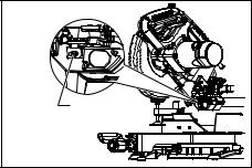
Laser line can be shifted to either the left or right side of the saw blade by loosening the screw holding the laser unit box and shifting it in the desired direction. After shifting, be sure to tighten the screw.
1 |
1. Screw holding the laser unit box
014275
Laser line is factory adjusted so that it is positioned within 1 mm from the side surface of the blade (cutting position).
NOTE:
•When laser line appears dim and hard to see because of direct sunlight, relocate the work area to a place where there is less direct sunlight.
Cleaning of the lens for the laser light
If the lens for the laser light becomes dirty, or sawdust adheres to it in such a way that the laser line is no longer easily visible, unplug the saw and remove and clean the lens for the laser light carefully with a damp, soft cloth. Do not use solvents or any petroleum-based cleaners on the lens.
NOTE:
•When laser line is dim and almost or entirely invisible because of the direct sunlight in the indoor or outdoor window-by work, relocate the work area to a place not exposed to the direct sunlight.
Light action
Fig.19
Fig.20
To turn on the light, press the upper position (ON) of the switch. To turn off the light, press the lower position (OFF) of the switch.
 CAUTION:
•Do not look in the light or see the source of light directly.
NOTE:
•Use a dry cloth to wipe the dirt off the lens of lamp.
•Be careful not to scratch the lens of lamp, or it may to lower the luminance.
ASSEMBLY
 WARNING:
•Always be sure that the tool is switched off and unplugged before working on the tool.
Failure to switch off and unplug the tool may result in serious personal injury.
Storage of socket wrench with hex wrench on its other end
Fig.21
The socket wrench is stored as shown in the figure. When the socket wrench is needed it can be pulled out of the wrench holder. After using the socket wrench it can be stored by returning it to the wrench holder.
13
Installing or removing saw blade
 WARNING:
•Always be sure that the tool is switched off and unplugged before installing or removing the blade. Accidental start up of the tool may result in serious personal injury.
•Use only the Makita socket wrench provided to install or remove the blade. Failure to use the wrench may result in overtightening or insufficient tightening of the hex bolt and serious personal injury.
Fig.22
Lock the handle in the raised position by pushing in the stopper pin.
Fig.23
To remove the blade, use the socket wrench to loosen the hex bolt holding the center cover by turning it counterclockwise. Raise the blade guard and center cover.
 WARNING:
•Do not remove any screw other than the hex bolt illustrated. If you mistakenly remove another screw and the blade guard comes off, make sure to re-assemble the blade guard.
Fig.24
Press the shaft lock to lock the spindle and use the socket wrench to loosen the hex bolt clockwise. Then remove the hex bolt, outer flange and blade.
NOTE:
•If the inner flange is removed be sure to install it on the spindle with its protrusion facing away from the blade. If the flange is installed incorrectly the flange will rub against the machine.
 WARNING:
•Before mounting the blade onto the spindle, always be sure that the correct ring for the blade's arbor hole you intend to use is installed between the inner and the outer flanges. Use of the incorrect arbor hole ring may result in the improper mounting of the blade causing blade movement and severe vibration resulting in possible loss of control during operation and in serious personal injury.
Fig.25
To install the blade, mount it carefully onto the spindle, making sure that the direction of the arrow on the surface of the blade matches the direction of the arrow on the blade case.
Install the outer flange and hex bolt, and then use the socket wrench to tighten the hex bolt (left-handed) securely counterclockwise while pressing the shaft lock.
For all countries other than European countries Fig.26
 CAUTION:
•The ring 25.4 mm in outer diameter is factory-
installed as shown in the figure.
For European countries
 CAUTION:
•The ring 30 mm in outer diameter is factory-
installed between the inner and outer flanges. Install the outer flange and hex bolt, and then use the socket wrench to tighten the hex bolt securely counterclockwise while pressing the shaft lock.
Fig.27
Return the blade guard and center cover to its original position. Then tighten the hex bolt clockwise to secure the center cover. Release the handle from the raised position by pulling the stopper pin. Lower the handle to make sure that the blade guard moves properly. Make sure the shaft lock has released spindle before making cut.
Dust bag
Fig.28
The use of the dust bag makes cutting operations cleaner and dust collection easier. To attach the dust bag, fit it onto the dust nozzle.
When the dust bag is about half full, remove the dust bag from the tool and pull the fastener out. Empty the dust bag of its contents, tapping it lightly so as to remove particles adhering to the insides which might hamper further collection.
NOTE:
If you connect a vacuum cleaner to your saw, cleaner operations can be performed.
Securing workpiece
 WARNING:
•It is extremely important to always secure the workpiece correctly with the proper type of vise or crown molding stoppers. Failure to do so may result in serious personal injury and cause damage to the tool and/or the workpiece.
•After a cutting operation do not raise the blade until it has come to a complete stop. The raising of a coasting blade may result in serious personal injury and damage to the workpiece.
•When cutting a workpiece that is longer than the support base of the saw, the material should be supported the entire length beyond the support base and at the same height to keep the material level. Proper workpiece support will help avoid blade pinch and possible kickback which may result in serious personal injury. Do not rely solely on the vertical vise and/or
14
horizontal vise to secure the workpiece. Thin material tends to sag. Support workpiece over its entire length to avoid blade pinch and possible KICKBACK.
Fig.29
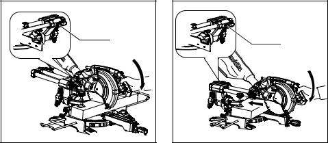
Guide fence (SLIDING FENCES) adjustment
Fig.30
 WARNING:
•Before operating the tool, make sure that the sliding fence is secured firmly.
•Before bevel-cutting, make sure that no part of the tool, especially the blade, contacts the sliding fence. when fully lowering and raising the handle in any position and while moving the carriage through its full range of travel. If the blade makes contact the sliding fence may result in kickback or unexpected movement of the material and serious personal injury.
Fig.31
 CAUTION:
•When performing bevel cuts, slide the sliding
fence to the left and secure it as shown in the figure. Otherwise, it will contact the blade or a part of the tool, causing possible serious injury to the operator.
This tool is equipped with the sliding fence which should ordinarily be positioned as shown in the figure. However, when performing left bevel cuts, set it to the left position as shown in the figure if the tool head contacts it.
When bevel-cutting operations are complete, don't forget to return the sliding fence to the original position and secure it by firmly tightening the clamping screw.
Vertical vise
Fig.32
The vertical vise can be installed on either the left or right side of the guide fence. Insert the vise rod into the hole in the guide fence and tighten the screw on the back of the guide fence to secure the vise rod.
Position the vise arm according to the thickness and shape of the workpiece and secure the vise arm by tightening the screw. If the screw to secure the vise arm contacts the guide fence, install the screw on the opposite side of vise arm. Make sure that no part of the tool contacts the vise when lowering the handle fully and pulling or pushing the carriage all the way. If some part contacts the vise, re-position the vise.
Press the workpiece flat against the guide fence and the turn base. Position the workpiece at the desired cutting position and secure it firmly by tightening the vise knob.
 WARNING:
•The workpiece must be secured firmly against the turn base and guide fence with the vise during all operations. If the workpiece is not
properly secured against the fence the material may move during the cutting operation causing possible damage to the blade, causing the material to be thrown and loss of control resulting in serious personal injury.
Holders
Fig.33
The holders can be installed on either side as a convenient means of holding workpieces horizontally. Slip fully the holder rods into the holes in the base. Then tighten the holders securely with the screws.
 WARNING:
•Always support a long workpiece so it is level with the top surface of the turn base for an accurate cut and to prevent dangerous loss of tool control. Proper workpiece support will help avoid blade pinch and possible kickback which may result in serious personal injury.
OPERATION
NOTICE:
•Before use, be sure to release the handle from the lowered position by pulling the stopper pin.
•Do not apply excessive pressure on the handle when cutting. Too much force may result in overload of the motor and/or decreased cutting efficiency. Push down handle with only as much force as is necessary for smooth cutting and without significant decrease in blade speed.
•Gently press down the handle to perform the cut. If the handle is pressed down with force or if lateral force is applied, the blade will vibrate and leave a mark (saw mark) in the workpiece and the precision of the cut will be impaired.
•During a slide cut, gently push the carriage toward the guide fence without stopping. If the carriage movement is stopped during the cut, a mark will be left in the workpiece and the precision of the cut will be impaired.
 WARNING:
•Make sure the blade is not contacting the workpiece, etc. before the switch is turned on.
Turning the tool on with the blade in contact with the workpiece may result in kickback and serious personal injury.
15
1.Press cutting (cutting small workpieces)
1 |
1. Locking screw
014290
Workpieces up to 90 mm high and 60 mm wide can be cut in the following manner.
Push the carriage toward the guide fence fully and tighten the locking screw clockwise to secure the carriage. Secure the workpiece correctly with the proper type of vise. Switch on the tool without the blade making any contact and wait until the blade attains full speed before lowering. Then gently lower the handle to the fully lowered position to cut the workpiece. When the cut is completed, switch off the tool and WAIT UNTIL THE BLADE HAS COME TO A COMPLETE STOP before returning the blade to its fully elevated position.
 WARNING:
•Firmly tighten the knob clockwise so that the carriage will not move during operation.
Insufficient tightening of the knob may cause possible kickback which may result in serious personal injury.
•Never cut so small workpiece which cannot be securely held by the vise. Improperly held workpiece may cause kickback and serious personal injury.
2.Slide (push) cutting (cutting wide workpieces)
1 |
1. Locking screw
014291
Loosen the locking screw counterclockwise so that the carriage can slide freely. Secure the workpiece with the proper type of vise. Pull the carriage toward you fully. Switch on the tool without the blade making any contact and wait until the blade attains full speed. Press the handle down and PUSH THE CARRIAGE TOWARD THE GUIDE FENCE AND THROUGH THE WORKPIECE. When the cut is completed, switch off the tool and WAIT UNTIL THE BLADE HAS COME TO A COMPLETE STOP before returning the blade to its fully elevated position.
 WARNING:
•Whenever performing a slide cut, first pull the carriage full towards you and press the handle all the way down, then push the carriage toward the guide fence. Never start the cut with the carriage not pulled fully toward you. If you perform the slide cut without the carriage pulled fully toward you unexpected kickback may occur and serious personal injury may result.
•Never attempt to perform a slide cut by pulling the carriage towards you. Pulling the carriage towards you while cutting may cause unexpected kickback resulting in possible serious personal injury.
•Never perform the slide cut with the handle locked in the lowered position.
•Never loosen the locking screw which secures the carriage while the blade is rotating. A loose carriage while cutting may cause unexpected kickback resulting in possible in serious personal injury.
16
3.Miter cutting
Refer to the previously covered "Adjusting the miter angle".
4.Bevel cut
Fig.34
Loosen the lever and tilt the saw blade to set the bevel angle (Refer to the previously covered "Adjusting the bevel angle"). Be sure to retighten the lever firmly to secure the selected bevel angle safely. Secure the workpiece with a vise. Make sure the carriage is pulled all the way back toward the operator. Switch on the tool without the blade making any contact and wait until the blade attains full speed. Then gently lower the handle to the fully lowered position while applying pressure in parallel with the blade and PUSH THE CARRIAGE TOWARD THE GUIDE FENCE TO CUT THE WORKPIECE. When the cut is completed, switch off the tool and WAIT UNTIL THE BLADE HAS COME TO A COMPLETE STOP before returning the blade to its fully elevated position.
WARNING:
•After setting the blade for a bevel cut, before operating the tool ensure that the carriage and blade will have free travel throughout the entire range of the intended cut. Interruption of the carriage or blade travel during the cutting operation may result in kickback and serious personal injury.
•While making a bevel cut keep hands out of the path of the blade. The angle of the blade may confuse the operator as to the actual blade path while cutting and contact with the blade will result in serious personal injury.
•The blade should not be raised until it has come to a complete stop. During a bevel cut the piece cut off may come to rest against the blade. If the blade is raised while it is rotating the cut-off piece maybe ejected by the blade causing the material to fragment which may result in serious
personal injury.
NOTICE:
•When pressing down the handle, apply pressure in parallel with the blade. If a force is applied perpendicularly to the turn base or if the pressure direction is changed during a cut, the precision of the cut will be impaired.
•Before bevel-cutting, an adjustment of sliding fence maybe required. Refer to the section titled "Guide fence adjustment".
5.Compound cutting
Compound cutting is the process in which a bevel angle is made at the same time in which a miter angle is being cut on a workpiece. Compound cutting can be performed at the angle shown in the table.
Miter angle |
Bevel angle |
Left and Right 0 - 45 |
Left 0 - 45 |
010340
When performing compound cutting, refer to "Press cutting", "Slide cutting", "Miter cutting" and "Bevel cut" explanations.
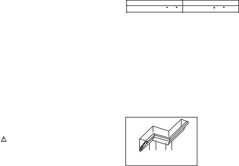
6.Cutting crown and cove moldings
Crown and cove moldings can be cut on a compound miter saw with the moldings laid flat on the turn base.
There are two common types of crown moldings and one type of cove moldings; 52/38° wall angle crown molding, 45° wall angle crown molding and 45° wall angle cove molding. See illustrations.
Fig.35
There are crown and cove molding joints which are made to fit "Inside" 90° corners ((1) and (2) in Fig. A) and "Outside" 90° corners ((3) and (4) in Fig. A).
1. Inside corner
2. Outside corner
|
(1) (2) |
(3)(4) |
|
|
|
|
|
Fig.A |
1 |
|
2 |
001556
Fig.36
Measuring
Measure the wall length and adjust workpiece on table to cut wall contact edge to desired length. Always make sure that cut workpiece length at the back of the workpiece is the same as wall length. Adjust cut length for angle of cut. Always use several pieces for test cuts to check the saw angles.
When cutting crown and cove moldings, set the bevel angle and miter angle as indicated in the table (A) and position the moldings on the top surface of the saw base as indicated in the table
(B).
In the case of left bevel cut
Table (A)
|
Molding |
Bevel angle |
Miter angle |
|||
|
position in |
|
|
|
|
|
|
Fig. A |
52/38° type |
45° type |
52/38° type |
45° type |
|
|
|
|
|
|
|
|
For inside |
(1) |
|
|
Right 31.6° |
Right 35.3° |
|
corner |
(2) |
|
|
|
|
|
|
Left 33.9° |
Left 30° |
Left 31.6° |
Left 35.3° |
||
For outside |
(3) |
|||||
|
|
|
|
|||
corner |
(4) |
|
|
Right 31.6° |
Right 35.3° |
|
|
|
|
||||
006361
17

Table (B)
|
|
Molding |
Molding edge against |
|
|
|
position in |
Finished piece |
|
|
|
guide fence |
||
|
|
Fig. A |
|
|
|
|
|
|
|
|
|
(1) |
Ceiling contact edge should |
Finished piece |
|
|
be against guide fence. |
||
|
|
will be on the |
||
|
For inside |
|
||
|
|
|
||
|
corner |
(2) |
|
Left side of |
|
|
Wall contact edge should be |
blade. |
|
|
|
|
|
|
|
For |
|
against guide fence. |
Finished piece |
|
(3) |
|
||
|
outside |
|
will be on the |
|
|
|
|
||
|
corner |
|
Ceiling contact edge should |
Right side of |
|
|
(4) |
blade. |
|
|
|
be against guide fence. |
||
|
|
|
|
|
|
|
|
|
|
|
006362 |
|
|
|
Example:
In the case of cutting 52/38° type crown molding for position (1) in Fig. A:
•Tilt and secure bevel angle setting to 33.9° LEFT.
•Adjust and secure miter angle setting to 31.6° RIGHT.
•Lay crown molding with its broad back (hidden) surface down on the turn base with its CEILING CONTACT EDGE against the guide fence on the saw.
•The finished piece to be used will always be on the LEFT side of the blade after the cut has been made.
7.Cutting aluminum extrusion
Fig.37
When securing aluminum extrusions, use spacer blocks or pieces of scrap as shown in the figure to prevent deformation of the aluminum. Use a cutting lubricant when cutting the aluminum extrusion to prevent build-up of the aluminum material on the blade.
 WARNING:
•Never attempt to cut thick or round aluminum extrusions. Thick or round aluminum extrusions can be difficult to secure and may work loose during the cutting operation which may result in loss of control and serious personal injury.
8.Wood facing
Use of wood facing helps to assure splinter-free cuts in workpieces. Attach a wood facing to the guide fence using the holes in the guide fence.
See the figure concerning the dimensions for a suggested wood facing.
15mm |
|
|
Over 450 mm |
|
|
|
|
62mm-65mm
|
|
|
18 mm |
1 |
45mm 103mm 103mm |
65mm |
1 |
1. Holes
014279
 CAUTION:
•Use straight wood of even thickness as the wood facing.
WARNING:
•Use screws to attach the wood facing to the guide fence. The screws should be installed so that the screw heads are below the surface of the wood facing so that they will not interfere with the positioning of the material being cut. Misalignment of the material being cut
can case unexpected movement during the cutting operation which may result in a loss of control and serious personal injury.
NOTICE:
•When the wood facing is attached, do not turn the turn base with the handle lowered. The blade and/or the wood facing will be damaged.
9.Groove cutting
Fig.38
A dado type cut can be made by proceeding as follows:
Adjust the lower limit position of the blade using the adjusting screw and the stopper arm to limit the cutting depth of the blade. Refer to "Stopper arm" section described previously.
After adjusting the lower limit position of the blade, cut parallel grooves across the width of the workpiece using a slide (push) cut as shown in the figure. Then remove the workpiece material between the grooves with a chisel.
 WARNING:
•Do not attempt to perform this type of cut by using a wider type blade or dado blade.
Attempting to make a groove cut with a wider blade or dado blade could lead to unexpected cutting results and kickback which may result in serious personal injury
•Be sure to return the stopper arm to the original position when performing other than groove cutting. Attempting to make cuts with the stopper arm in the incorrect position could lead to unexpected cutting results and kickback which may result in serious personal injury.
 CAUTION:
•Be sure to return the stopper arm to the original position when performing other than groove cutting.
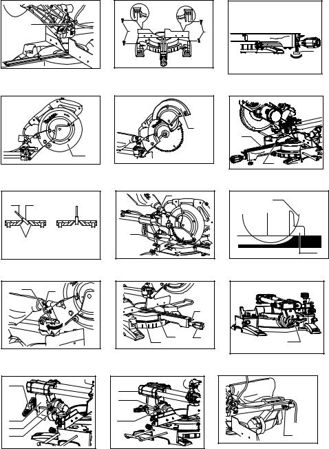
Carrying tool
Fig.39
Make sure that the tool is unplugged. Secure the blade at 0° bevel angle and the turn base at the full right miter angle position. Secure the slide poles so that the lower slide pole is locked in the position of the carriage fully pulled to operator and the upper poles are locked in the
18

position of the carriage fully pushed forward to the guide fence (refer to the section titled "Slide lock adjustment ".) Lower the handle fully and lock it in the lowered position by pushing in the stopper pin.
Wind the power supply cord using the cord rests.
WARNING:
•Stopper pin is only for carrying and storage
purposes and should never be used for any cutting operations. The use of the stopper pin for cutting operations may cause unexpected movement of the saw blade resulting in kickback and serious personal injury.
Carry the tool by holding both sides of the tool base as shown in the figure. If you remove the holders, dust bag, etc., you can carry the tool more easily.
 CAUTION:
•Always secure all moving portions before carrying the tool. If portions of the tool move or slide while being carried loss of control or balance may occur resulting in personal injury.
MAINTENANCE
WARNING:
•Always be sure that the tool is switched off and unplugged before attempting to perform inspection or maintenance. Failure to unplug and switch off the tool may result in accidental start up of the tool which may result in serious personal injury.
•Always be sure that the blade is sharp and clean for the best and safest performance. Attempting a cut with a dull and /or dirty blade may cause kickback and result in a serious personal injury.
NOTICE:
•Never use gasoline, benzine, thinner, alcohol or the like. Discoloration, deformation or cracks may result.
Adjusting the cutting angle
This tool is carefully adjusted and aligned at the factory, but rough handling may have affected the alignment. If your tool is not aligned properly, perform the following:
1.Miter angle
Fig.40
Push the carriage toward the guide fence and tighten the locking screw to secure the carriage. Loosen the grip which secures the turn base. Turn the turn base so that the pointer points to 0° on the miter scale. Then turn the turn base slightly clockwise and counterclockwise to seat the turn base in the 0° miter notch. (Leave as it is if the pointer does not point to 0°.) Loosen the hex sockets bolts securing the guide fence using the socket wrench.
Fig.41
Lower the handle fully and lock it in the lowered position by pushing in the stopper pin. Square the side of the blade with the face of the guide fence using a triangular rule, try-square, etc. Then securely tighten the hex socket bolts on the guide fence in order starting from the right side.
Fig.42
Make sure that the pointer points to 0° on the miter scale. If the pointer does not point to 0°, loosen the screw which secures the pointer and adjust the pointer so that it will point to 0°.
2.Bevel angle
(1)0° bevel angle
Fig.43
Push the carriage toward the guide fence and tighten the locking screw to secure the carriage. Lower the handle fully and lock it in the lowered position by pushing in the stopper pin. Loosen the lever at the rear of the tool.
Fig.44
Turn the hex bolt on the right side of the arm two or three revolutions counterclockwise to tilt the blade to the right.
Fig.45
Carefully square the side of the blade with the top surface of the turn base using the triangular rule, try-square, etc. by turning the hex bolt on the right side of the arm clockwise. Then tighten the lever securely.
Fig.46
Make sure that the pointer on the arm point to 0° on the bevel scale on the arm holder. If they do not point to 0°, loosen the screw which secure the pointer and adjust it so that it will point to 0°.
(2)45° bevel angle
Fig.47
Adjust the 45° bevel angle only after performing 0° bevel angle adjustment. To adjust left 45° bevel angle, loosen the lever and tilt the blade to the left fully. Make sure that the pointer on the arm points to 45° on the bevel scale on the arm holder. If the pointer does not point to 45°, turn the 45° bevel angle adjusting bolt on the right side of the arm holder until the pointer points to 45°. To adjust the right 5° bevel angle, perform the same procedure as that described above.
19

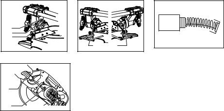
Replacing carbon brushes
Fig.48
Remove and check the carbon brushes regularly. Replace when they wear down to 3 mm in length. Keep the carbon brushes clean and free to slip in the holders. Both carbon brushes should be replaced at the same time. Use only identical carbon brushes.
Fig.49
Use a screwdriver to remove the brush holder caps. Take out the worn carbon brushes, insert the new ones and secure the brush holder caps.
After use
•After use, wipe off chips and dust adhering to the tool with a cloth or the like. Keep the blade guard clean according to the directions in the previously covered section titled "Blade guard". Lubricate the sliding portions with machine oil to prevent rust.
•When storing the tool, pull the carriage toward you fully.
To maintain product SAFETY and RELIABILITY, repairs, any other maintenance or adjustment should be performed by Makita Authorized Service Centers, always using Makita replacement parts.
OPTIONAL ACCESSORIES
WARNING:
•These Makita accessories or attachments are recommended for use with your Makita tool specified in this manual. The use of any other accessories or attachments may result in serious personal injury.
•Only use the Makita accessory or attachment
for its stated purpose. Misuse of an accessory or attachment may result in serious personal injury.
If you need any assistance for more details regarding these accessories, ask your local Makita Service Center.
•Steel & Carbide-tipped saw blades
Miter saw blades |
For smooth and precise cutting in various materials. |
|
|
|
|
Combination |
General purpose blade for fast and smooth rip, |
|
crosscuts and miters. |
||
|
||
Crosscutting |
For smoother cross grain cuts. Slices cleanly |
|
against the grain. |
||
|
||
|
|
|
Fine cross cuts |
For sand-free cuts cleanly against the grain. |
|
|
|
|
Non-ferrous metals |
For miters in aluminum, copper, brass, tubing, |
|
miter saw blades |
and other non-ferrous metals. |
|
|
|
006526
•Vertical vise
•Socket wrench with hex wrench on its other end
•Holder
•Dust bag
•Triangular rule
NOTE:
•Some items in the list may be included in the tool package as standard accessories. They may differ from country to country.
20
SVENSKA (Originalbruksanvisning)
Förklaring till översiktsbilderna
1-1. Låstapp |
20-1. Strömbrytare för lampa |
32-4. Skruv |
2-1. Skruvar |
21-1. Hylsnyckel med insexnyckel på |
32-5. Anslag |
3-1. Inställningsbult |
dess andra ände |
33-1. Hållare |
4-1. Klingskydd |
21-2. Nyckelhållare |
33-2. Skruv |
5-1. Klingskydd |
22-1. Låstapp |
35-1. 52/38 kronlist |
6-1. Spårbädd |
23-1. Hylsnyckel |
35-2. 45 kronlist |
6-2. Skruv |
23-2. Klingkåpa |
35-3. 45 hållist |
7-1. Sågblad |
23-3. Mitthölje |
36-1. Insidan av hörn |
7-2. Sågtänder |
23-4. Sexkantskruv |
36-2. Utsidan av hörn |
7-3. Spårbädd |
23-5. Klingskydd |
37-1. Anslag |
7-4. Vinkelsågning åt vänster |
24-1. Klingkåpa |
37-2. Tving |
7-5. Rak sågning |
24-2. Hylsnyckel |
37-3. Distanskloss |
8-1. Inställningsbult |
24-3. Sexkantskruv |
37-4. Aluminiumstycke |
8-2. Geringsskiva |
24-4. Pil |
37-5. Distanskloss |
9-1. Geringsskivans ovansida |
24-5. Spindellås |
38-1. Såga spår med blad |
9-2. Klingans ytterkant |
25-1. Klingkåpa |
40-1. Anslag |
9-3. Anslag |
25-2. Pil |
40-2. Sexkantsbultar |
10-1. Stopparm |
25-3. Pil |
40-3. Handtag |
10-2. Inställningsskruv |
25-4. Sågblad |
41-1. Anslag |
11-1. Geringsskala |
26-1. Sexkantskruv (vänstergängad) |
41-2. Vinkelhake |
11-2. Pil |
26-2. Yttre fläns |
42-1. Skruv |
11-3. Låsknapp |
26-3. Sågblad |
42-2. Pil |
11-4. Handtag |
26-4. Ring |
42-3. Geringsskala |
12-1. Spak |
26-5. Innerfläns |
43-1. Spak |
13-1. Spak |
26-6. Spindel |
43-2. Arm |
13-2. Arm |
27-1. Hylsnyckel |
44-1. Justeringsskruv 0 |
13-3. Pil |
27-2. Klingkåpa |
44-2. Justeringsskruv för vänster 45 |
13-4. Vinkelskala |
27-3. Mitthölje |
vinkel |
14-1. Pil |
27-4. Sexkantskruv |
45-1. Vinkelhake |
14-2. Frikopplingsknapp |
27-5. Klingskydd |
45-2. Sågblad |
14-3. Vinkelskala |
28-1. Dammunstycke |
45-3. Geringsskivans ovansida |
15-1. Låsskruv |
28-2. Dammpåse |
46-1. Skruv |
16-1. Säkerhetsknapp |
28-3. Fästanordning |
46-2. Pil |
16-2. Spak |
29-1. Stöd |
46-3. Vinkelskala |
16-3. Avtryckare |
29-2. Geringsskiva |
47-1. Höger 5 justermutter för |
16-4. Hål för hänglås |
30-1. Skjutbart anhåll |
snedställning |
17-1. Säkerhetsknapp |
30-2. Låsskruv |
47-2. Justeringsskruv för vänster 45 |
17-2. Avtryckare |
31-1. Skjutbart anhåll |
vinkel |
17-3. Hål för hänglås |
32-1. Tvingarm |
49-1. Skruvmejsel |
18-1. Strömbrytare till laser |
32-2. Tvingens ratt |
49-2. Kolhållarlock |
19-1. Lampa |
32-3. Stång till tving |
|
|
|
|
21

SPECIFIKATIONER
Modell |
|
|
LS0815F / LS0815FL |
|
Bladdiameter |
|
|
|
216 mm |
Bladtjocklek |
|
|
|
1,5 - 2,5 mm |
Håldiameter |
|
|
|
|
- För alla länder utanför Europa |
|
|
|
25,4 mm |
- För länder i Europa |
|
|
|
30 mm |
Max. geringsvinkel |
|
|
Vänster 50° Höger 60° |
|
Max. sågvinkel |
|
|
Vänster 48° Höger 5° |
|
Max. sågkapacitet (H x B) med 216 mm i diameter |
|
|
|
|
Geringsvinkel |
|
Vinkel för vinkelsågning |
||
45° (vänster) |
5° (höger) |
|
0° |
|
|
|
|||
0° |
50 mm x 305 mm |
60 mm x 305 mm |
|
65 mm x 305 mm |
45° |
50 mm x 215 mm |
- |
|
65 mm x 215 mm |
60° (höger) |
- |
- |
|
65 mm x 150 mm |
Märkspänning |
|
|
220 - 240 V, 50 - 60 Hz |
|
Märkeffekt |
|
1 400 W, S6 40 % 5 min |
||
Obelastat varvtal (min-1) |
|
|
5 000 |
|
Endast lasertyp (LS0815FL) |
|
Röd laser 650 nm, |
|
1mW (laserklass 2) |
Mått (L x B x H) |
|
755 mm x 450 mm x 488 mm |
||
Vikt |
|
För alla länder utanför Europa•••14,1 kg |
||
|
|
För länder i Europa•••LS0815F 14,1 kg |
||
|
|
|
••• LS0815FL 14,2 kg |
|
Säkerhetsklass |
|
|
|
/II |
•På grund av vårt pågående program för forskning och utveckling kan dessa specifikationer ändras utan föregående meddelande.
•Specifikationerna kan variera mellan olika länder.
•Vikt i enlighet med EPTA-procedur 01/2003
END223-4
Symboler
Följande visar symbolerna som används för utrustningen. Se till att du förstår innebörden innan du använder borrmaskinen.
Läs bruksanvisningen.
DUBBEL ISOLERING
Undvik skador från flygande materialrester genom att fortsätt hålla ned såghuvudet efter sågningen tills klingan har stannat helt.
Vid bakåtriktad sågning, dra först löpvagnen ut så långt som möjligt, tryck sedan ned handtaget, skjut sedan löpvagnen mot anhållet.
Håll inte handen eller fingrarna i närheten av sågbladet.
Justera de skjutbara anhållen bort från klingan och klingskyddet.
LASERSTRÅLNING: Titta inte in i strålen. Direkta laserstrålar kan skada ögonen.
Gäller endast EU-länder
Elektrisk utrustning får inte kastas i hushållssoporna!
Enligt EU-direktivet som avser äldre elektrisk och elektronisk utrustning och dess tillämpning enligt nationell lagstiftning ska uttjänt elektriskt utrustning sorteras separat och lämnas till miljövänlig återvinning.
ENE006-1
Användningsområde
Verktyget är avsett för exakt rätoch geringssågning i trä. Med lämpliga sågblad kan man även såga i aluminium.
ENF002-2
Strömförsörjning
Maskinen får endast anslutas till elnät med samma spänning som anges på typplåten och med enfasig växelström. De är dubbelisolerade och får därför också anslutas i ojordade vägguttag.
ENG905-1
Buller
Typiska A-vägda bullernivån är mätt enligt EN61029:
Ljudtrycksnivå (LpA) : 87 dB (A)
Ljudtrycksnivå (LWA) : 110 dB (A)
Mättolerans (K) : 3 dB (A)
Använd hörselskydd
22

ENG900-1
Vibration
Vibrationens totalvärde (tre-axlars vektorsumma) mätt enligtEN61029 :
Vibrationsemission (ah): 2,5 m/s2 eller mindre Mättolerans (K): 1,5 m/s2
ENG901-1
•Det deklarerade vibrationsemissionsvärdet har uppmätts i enlighet med standardtestmetoden och kan användas för jämförandet av en maskin med en annan.
•Det deklarerade vibrationsemissionsvärdet kan också användas i preliminär bedömning av exponering för vibration.
 VARNING!
•Viberationsemissionen under faktisk användning av maskinen kan skilja sig från det deklarerade emissionsvärdet, beroende på hur maskinen används.
•Se till att hitta säkerhetsåtgärder som kan skydda användaren och som grundar sig på en uppskattning av exponering i verkligheten (ta med i beräkningen alla delar av användandet såsom antal gånger maskinen är avstängd och när den körs på tomgång samt då startomkopplaren används).
ENH103-1
Gäller endast Europa
EU-konformitetsdeklaration
Makita försäkrar att följande maskiner:
Maskinbeteckning:
Skjutbar kapoch geringskombinationssåg Modellnr./Typ:
LS0815F, LS0815FL
Följer följande EU-direktiv:
2006/42/EC, 2006/95/EC, 2006/108/EC, 2006/65/EC
De är tillverkade i enlighet med följande standard eller standardiseringsdokument:
EN61029, EN 55014-1, EN 55014-2, EN 61000-3-2, EN 61000-3-3
Den tekniska dokumentationen i enlighet med 2006/42/EG finns tillgänglig från:
Makita, Jan-Baptist Vinkstraat 2, 3070, Belgium
20.12.2013
000331
Yasushi Fukaya
Direktör
Makita, Jan-Baptist Vinkstraat 2, 3070, Belgium
GEA010-1
Allmänna säkerhetsvarningar för maskin
 VARNING Läs igenom alla säkerhetsvarningar och instruktioner. Underlåtenhet att följa varningar och instruktioner kan leda till elektrisk stöt, brand och/eller allvarliga personskador.
Spara alla varningar och instruktioner
för framtida referens.
ENB034-7
YTTERLIGARE SÄKERHETSANVISNINGAR FÖR MASKINEN
1.Använd ögonskydd.
2.Håll händerna borta från bladets såglinje. Undvik kontakt med sågklingan. Den kan fortfarande orsaka allvarliga skador.
3.Använd inte sågen om inte skydden är på plats. Kontrollera att det nedre skyddet är stängt före varje sågning. Använd inte sågen om det nedre skyddet kärvar och inte stängs omedelbart. Kila aldrig fast klingskyddet i öppet läge.
4.Utför aldrig sågning på frihand. Arbetsstycket
måste sitta fast ordentligt mot |
bordet |
och |
||
anslaget |
med |
skruvstycket |
under |
alla |
arbetsmoment. Håll aldrig arbetsstycket med handen.
5.Sträck dig aldrig runt sågbladet.
6.Stäng av verktyget och vänta tills sågbladet stannat innan du flyttar arbetsstycket eller ändrar inställningar.
7.Ta ut nätsladden före byte av sågblad eller service.
8.Fäst alltid alla rörliga delar innan du bär verktyget.
9.Låspinnen som låser såghuvudet på plats är endast avsedd att användas vid förvaring eller transport och inte för sågning.
10.Använd inte maskiner i närheten av lättantändliga vätskor eller gaser. När maskinen är igång kan den skapa en explosion och brand när den utsätts för lättantändliga vätskor eller gaser.
11.Kontrollera att bladet inte är skadat eller sprucket före användning.
Byt omedelbart ut ett skadat eller sprucket sågblad.
12.Använd endast flänsar avsedda för den här maskinen.
13.Var försiktig så att inte axeln, flänsarna (särskilt monteringsytan) eller bulten inte skadas. Skador på någon av dessa delar kan medföra att bladet förstörs.
23
14.Se till att bordet är ordentligt fast, så att det inte rör sig under arbetet.
15.Avlägsna av säkerhetsskäl spån, småbitar etc. från bordets översida innan arbetet påbörjas.
16.Undvik att såga i spik. Kontrollera arbetsstycket och ta bort alla spikar före
arbetet.
17. Se till att spindellåset är öppet innan strömbrytaren slås på.
18.Kontrollera att bladet i sin lägsta position inte vidrör bordet.
område och arbeta med godkänd säkerhetsutrustning som till exempel dammask vilken skapats speciellt för filtrering av mikroskopiska partiklar.
34.För att minska bullret, se alltid till att sågbladet är vasst och rengjort.
35.Att operatören är tillräckligt utbildad i användning, justering och drift av maskinen.
36.Använd korrekt slipade sågblad. Observera maximal hastighet som markerats på sågbladet.
19.Håll handtaget stadigt. Var uppmärksam på att 37. Ta inte bort avsågade bitar eller andra delar av
sågen rör sig något upp och ned under start och stopp.
20.Se till att sågbladet inte är i kontakt med arbetsstycket innan du trycker på avtryckaren.
21.Låt verktyget vara igång en stund innan det används på arbetsstycket. Kontrollera att sågbladet inte vibrerar eller skakar vilket kan innebära att den är felaktigt monterad eller dåligt balanserad.
22.Vänta tills bladet når full hastighet innan du skär.
23.Stanna maskinen omedelbart om du lägger märke till något onormalt.
24.Försök inte att låsa avtryckaren i påslaget läge.
25.Var alltid uppmärksam, särskilt under upprepade och monotona arbeten. Låt dig inte vaggas in i falsk säkerhet. Sågblad är mycket farliga.
26.Använd alltid de tillbehör som rekommenderas i denna bruksanvisning. Opassande tillbehör som till exempel sliprondeller kan orsaka skada om de används.
27.Använd inte sågen till annat än för sågning av trä, aluminium eller liknande material.
28.Anslut geringssågar till en anordning för dammuppsamling innan sågning.
29.Välj sågblad som passar det material som skall sågas.
30.Var försiktig vid spårsågning.
31.Byt ut sågskäret när det är slitet.
32.Använd inte sågblad som tillverkats av snabbstål.
33.Visst damm som skapas vid användning innehåller kemikalier som kan orsaka cancer, födelsedefekter eller annan skada vid fortplantning. Några exempel på dessa kemikalier är:
•bly från material målat med blybaserad färg och
•arsenik och krom från kemiskt behandlat virke.
Riskerna vid exponering varierar beroende på hur ofta du utför denna typ av arbete. För att minska risken för exponering av dessa kemikalier: arbeta i ett välventilerat
arbetsstycket från sågningsområdet när maskinen körs och såghuvudet inte är i sitt viloläge.
38.Använd endast de sågblad som rekommenderas av tillverkaren vilka överensstämmer med EN847-1.
39.Bär alltid handskar när du hanterar sågblad (sågblad ska alltid bäras i en hållare om det är möjligt) och grova material.
40.Håll golvet rent från löst material, t.ex. spån och avsågade bitar.
41.När maskinen är utrustad med laser, får den inte bytas ut mot en annan sorts laser. Reparationer ska endast utföras på ett korrekt sätt.
SPARA DESSA ANVISNINGAR.
INSTALLATION
Bänkmontering
Fig.1
När maskinen levereras från fabriken är handtaget låst i nedsänkt läge av låstappen. Ta bort låstappen genom att lätt tryck nedåt på handtaget samtidigt som du drar ut låstappen.
 VARNING!
•Se till att maskinen inte kan röra sig på stödytan. Om geringssågen rör sig på stödytan medan du sågar kan det leda till att du tappar kontrollen över maskinen och att allvarlig personskada uppstår.
Fig.2
Maskinen skall fästas på en plan och stabil yta med fyra bultar i de bulthål som finns i maskinens sågbord. Detta förhindrar att maskinen välter och orsakar skada.
Fig.3
Vrid justermuttern medsols eller motsols så att den kommer i kontakt med verktygets yta och fixerar verktyget.
24
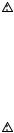
FUNKTIONSBESKRIVNING
 VARNING!
•Se alltid till att maskinen är avstängd och att nätsladden är urdragen innan du justerar eller funktionskontrollerar maskinen. I annat fall kan det leda till möjlig allvarlig personskada vid en oavsiktlig start.
Klingskydd
Fig.4
När handtaget sänks ned, höjs klingskyddet automatiskt. Klingskyddet återgår till sitt ursprungliga läge när sågningen är avslutad och handtaget är upphöjt.
VARNING!
•Blockera aldrig eller avlägsna klingskyddet eller den fjäder som är fäst på skyddet. I annat fall kan det leda till allvarlig personskada under
användningen.
För din personliga säkerhet bör klingskyddet alltid hållas i gott skick. Om klingskyddet inte fungerar som det ska måste detta åtgärdas direkt. Kontrollera även att fjädern gör att klingskyddet går tillbaka.
VARNING!
•Använd aldrig maskinen om klingskyddet eller fjädern är skadad, inte fungerar korrekt eller är borttagen. I annat fall kan det leda till allvarlig personskada.
Om det genomskinliga klingskyddet blir smutsigt eller om sågspån fastnar på det så att klingan och/eller arbetsstycket inte syns bra, måste maskinen kopplas bort från elnätet och skyddet rengöras noga med en fuktig trasa. Använd inte lösningsmedel eller petroleumbaserade rengöringsmedel då det skadar plasten i skyddet.
Om klingskyddet blir smutsigt och behöver rengöras, följ stegen nedan:
Med maskinen avstängd och nätsladden urdragen ska medföljande hylsnyckel användas för att lossa insexbulten som fäster mitthöljet. Lossa insexbulten moturs och lyft klingskyddet och mitthöljet.
Fig.5
Med klingskyddet i detta läge är en mer noggrann och effektiv rengöring möjlig. När rengöringen är klar utför du proceduren ovan på motsatt sätt och drar åt bulten. Ta inte bort det fjäderupphängda klingskyddet. Om klingskyddet blir skadat p.g.a. UV-ljus eller genom slitage kontaktar du ett Makita servicecenter för att få ett nytt klingskydd. KLINGSKYDDET FÅR ALDRIG
BLOCKERAS ELLER TAS BORT.
Inställning av spårbädd
Fig.6
Fig.7
Denna maskin är utrustad med spårbädden infälld i geringsskivan, för att göra slitaget vid utgången av sågningen så minimalt som möjligt. Spårbädden är fabriksinställd så att sågklingan inte kommer i kontakt med den. Ställ in spårbädden på följande sätt före användning:
Koppla först bort maskinen från elnätet. Lossa alla skruvar (3 skruvar på vardera vänster och höger sida) som håller fast spårbäddarna. Dra åt dem igen men endast så mycket att spårbäddarna fortfarande lätt kan röras för hand. Sänk ner handtaget helt och tryck in låstappen för att fästa handtaget i det nedsänkta läget. Lossa skruven som fäster skjutstängerna. Dra vagnen mot dig helt och hållet. Justera spårbäddarna så att de precis vidrör sidorna på sågklingans tänder. Dra åt de främre skruvarna (dra inte åt hårt). Skjut vagnen helt mot anhållet och justera spårbäddarna så att de precis lätt vidrör sidorna på klingans sågtänder. Dra åt de bakre skruvarna (dra inte åt hårt).
Dra ur låstappen och lyft handtaget efter att spårbäddarna justerats. Dra sedan åt alla skruvar ordentligt.
OBS:
•Försäkra dig om att spårbäddarna är korrekt justerad efter att du ställt in vinkeln för vinkelsågning. Korrekt justering av spårbäddarna ger ordentligt stöd för arbetsstycket och minimerar risken för att arbetsstycket nöts sönder.
Upprätthållande av maximal sågkapacitet
Detta verktyg är inställt på fabrik för maximal skärkapacitet för en 216 mm sågklinga.
Dra ur kontakten innan du gör några justeringar. Kontrollera alltid undre gränsläget för klingan när en ny sådan installeras och justera efter behov enligt följande:
Fig.8
Fig.9
Koppla först bort maskinen från elnätet. Tryck vagnen fullt mot anhållet och sänk maskinhandtaget helt och hållet. Använd insexnyckeln för att vrida inställningsbulten tills klingans ytterkant sticker ut en aning under geringsskivan, vid den punkt där anhållets framsida kommer i kontakt med geringsskivans ovansida.
Kontrollera att maskinens nätsladd är utdragen och snurra på klingan för hand, medan handtaget hålls ner fullständigt, och kontrollera att klingan inte kommer i kontakt med någon del av undre basplattan. Finjustera inställningen vid behov.
 VARNING!
•Efter monteringen av en ny klinga och med nätsladden urdragen måste du alltid kontrollera att klingan inte går emot någon del av den undre basplattan när handtaget sänks ner helt. I annat fall kan det orsaka bakåtkast och resultera i allvarlig personskada.
25

Stopparm
Fig.10
Den lägsta positionen för klingan kan enkelt justeras med stopparmen. Justera höjden genom att först föra stopparmen i pilens riktning, såsom visas i figuren. Justera inställningsskruven så att klingan stannar på önskat läge när maskinhandtaget sänks maximalt.
Justering av geringsvinkeln
Fig.11
Lossa handtaget genom att vrida det moturs. Vrid geringsskivan medan låsspaken hålls nedtryckt. Dra åt handtaget ordentligt genom att vrida det medurs, när handtaget flyttats till det läge där pekaren indikerar önskad vinkel på geringsskalan.
 FÖRSIKTIGT!
•Fäst alltid geringsskivan genom att dra åt handtaget ordentligt efter ändringen av geringsvinkeln.
OBS:
• Lyft handtaget maximalt när geringsskivan vrids.
Justering av vinkeln vid vinkelsågning
Fig.12
För att ändra vinkeln för vinkelsågning, lossar du spaken på maskinens baksida genom att dra den moturs. Frigör armen genom att trycka maskinhandtaget ganska kraftigt åt det håll du önskar luta klingan åt.
OBS!
•Spaken kan justeras till en annan vinkel genom att ta bort skruven som fäster spaken och fästa spaken i önskad vinkel.
Fig.13
Luta sågklingan tills pekaren indikerar önskad vinkeln på vinkelskalan. Dra sedan åt spaken medurs ordentligt för att fästa armen.
Fig.14
För att vinkla sågklingan åt höger 5 eller vänster 48 : Ställ in sågklingan på 0 för höger 5 , eller45 för vänster 48 . Vinkla sedan sågklingan lätt åt motsatt håll. Tryck på frigörningsknappen och vinkla sågklingan till önskad position. Spänn spaken för att låsa fast stödet.
 FÖRSIKTIGT!
•Fäst alltid armen genom att dra åt spaken medurs
efter ändringen av vinkeln för vinkelsågning.
OBS:
•Lyft handtaget maximalt när sågklingan lutas.
•Vid ändring av vinkeln för vinkelsågning måste spårbädden ställas in ordentligt såsom beskrivits i avsnittet "Inställning av spårbäddar".
Inställning av skjutlås
Fig.15
Vrid låsskruven medurs för att låsa skjutstången.
Avtryckarens funktion
För länder i Europa
Fig.16
En säkerhetsknapp förhindrar oavsiktlig aktivering av avtryckaren. För att starta maskinen för du spaken till vänster, trycker in säkerhetsknappen och sedan avtryckaren. Släpp avtryckaren för att stoppa maskinen.
VARNING!
•Innan du ansluter maskinen till elnätet ska du alltid kontrollera att avtryckaren fungerar och återgår till läget "OFF" när du släpper den. Tryck inte in avtryckaren hårt utan att ha tryckt in säkerhetsknappen. I annat fall kan avtryckaren gå sönder. Att använda en maskin
med en avtryckare som inte fungerar korrekt kan leda till att du tappar kontrollen över maskinen och orsaka allvarlig personskada.
Avtryckaren är försedd med ett hål för isättning av hänglås för att låsa maskinen.
För alla länder utanför Europa
Fig.17
En säkerhetsknapp förhindrar oavsiktlig aktivering av avtryckaren. Tryck in säkerhetsknappen och tryck sedan in avtryckaren för att starta maskinen. Släpp avtryckaren för att stoppa maskinen.
VARNING!
•Innan du ansluter maskinen till elnätet ska du alltid kontrollera att avtryckaren fungerar och återgår till läget "OFF" när du släpper den. Tryck inte in avtryckaren hårt utan att ha tryckt in säkerhetsknappen. I annat fall kan avtryckaren gå sönder. Att använda en maskin
med en avtryckare som inte fungerar korrekt kan leda till att du tappar kontrollen över maskinen och orsaka allvarlig personskada.
Avtryckaren är försedd med ett hål för isättning av hänglås för att låsa maskinen.
 VARNING!
•Använd inte ett lås med en "nacke" eller kabel som är smalare än 6,35 mm i diameter. En smalare "nacke“ eller kabel låser eventuellt inte maskinen i off-läget och oavsiktlig aktivering kan uppstå vilket resulterar i allvarlig personskada.
•Använd ALDRIG maskinen om inte avtryckaren fungerar riktigt. Att använda maskinen när inte avtryckaren fungerar är MYCKET FARLIGT. Reparera den före fortsatt användning eftersom det annars kan orsaka allvarlig personskada.
•Denna maskin är utrustat med en säkerhetsknapp som förhindrar oavsiktlig start. Använd ALDRIG maskinen om den startar när du trycker på avtryckaren utan att ha tryckt in säkerhetsknappen. I annat fall kan det orsaka oavsiktlig aktivering och allvarlig personskada. Returnera maskinen till ett
26

MAKITA servicecenter för reparation INNAN du fortsätter att använda den.
•Blockera ALDRIG säkerhetsknappen genom att tejpa fast den m.m. I annat fall kan det orsaka oavsiktlig aktivering och allvarlig personskada.
Elektronisk funktion
Mjukstartfunktion
•Denna funktion ger en mjuk uppstart av maskinen genom att begränsa vridmomentet vid uppstarten.
Laserstrålens funktion
Endast för modell LS0815FL
OBS!
•Innan maskinen används för första gången ska du montera torrbatterierna, som skickas med separat, i batterilådan. Se avsnittet med rubriken “Utbyte av torrbatterierna i laserenheten” för montering.
 FÖRSIKTIGT!
•Var noga med att stänga av lasern när den inte används
Fig.18
 FÖRSIKTIGT!
•Titta aldrig in i laserstrålen. Direkt laserljus kan skada ögonen.
•LASERSTRÅLNING, TITTA INTE DIREKT IN I STRÅLEN MED OPTISKA INSTRUMENT, KLASS 2M LASERPRODUKT.
•Se till att koppla bort maskinen från elnätet innan laserlinjen ändras eller när underhåll eller justering utförs.
Laserstrålen tänds genom att trycka på omkopplarens övre läge (ON). Strålen släcks genom att trycka på omkopplarens undre läge (OFF).
Laserlinjen kan förskjutas endera mot vänster eller höger sida av sågklingan genom att lossa laserenhetens fästskruv och vrida enheten åt önskat håll. Se till att dra åt skruven efter att förskjutningen gjorts.
1 |
1. Skruv som fäster laserenheten
014275
Laserlinsen är fabriksinställd så att den ligger inom 1 mm från sågklingans sida (sågposition).
OBS!
•När laserlinjen verkar oklar och är svår att se på grund av direkt solljus ska du byta till en mer skuggig arbetsplats.
Rengöring av laserns lins
Om laserns lins blir smutsig eller om sågspån fastnar på den så att inte laserlinjen syns stänger du av maskinen, tar bort linsen och rengör den försiktigt med en fuktig mjuk trasa. Använd inte lösningsmedel eller petroleumbaserade rengöringsmedel på linsen.
OBS!
•När laserlinjen är suddig och nästan helt osynlig på grund av direkt solbelysning, inne eller ute, flyttar du arbetsplatsen till en plats som inte är solbelyst.
Ljusmanöver
Fig.19
Fig.20
Tänd ljuset genom att trycka på omkopplarens övre del (ON). Släck ljuset genom att trycka på omkopplarens undre del (OFF).
 FÖRSIKTIGT!
•Titta inte in i ljuset eller direkt i ljuskällan.
OBS!
•Använd en torr trasa för att torka bort smuts från lampan.
•Var försiktig med att inte repa lampans lins, eftersom det kan minska ljusstyrkan.
MONTERING
 VARNING!
•Se till att verktyget alltid är frånslaget och att kontakten är urdragen före åtgärder på verktyget.
Underlåtenhet att stänga av och koppla ifrån verktyget kan leda till allvarlig personskada.
Förvaring av hylsnyckel med insexnyckel på dess andra ände
Fig.21
Hylsnyckeln förvaras på det sätt som framgår av bilden. När hylsnyckeln behöver användas kan den dras ut ur dess hållare. Efter användningen kan du förvara den i dess hållare igen.
Montering eller borttagning av sågblad
 VARNING!
•Se alltid till att maskinen är avstängd och nätsladden urdragen innan du monterar eller tar bort sågklingan. Oavsiktlig start av maskinen kan leda till allvarlig personskada.
•Använd endast den Makita-nyckel som levereras med verktyget för att sätta fast eller ta bort klingan. Underlåtenhet att använda nyckeln kan leda till för hård eller för lös åtdragning av sexkantsbulten och vålla allvarlig personskada.
27
Fig.22
Lås handtaget i det upphöjda läget genom att trycka in låstappen.
Fig.23
När du ska ta ur klingan använder du hylsnyckeln för att lossa på insexbulten som håller fast mitthöljet, genom att vrida den moturs. Lyft på klingskyddet och mitthöljet.
 VARNING!
•Ta inte bort någon annan skruv än den illustrerade sexkantsbulten. Om du av misstag tar bort andra skruvar och klingskyddet lossnar ska du se till att montera klingskyddet igen.
Fig.24
Tryck på spindellåset för att låsa spindeln och använd hylsnyckeln för att lossa på insexbulten genom att vrida den medurs. Ta sedan bort insexbulten, den yttre flänsen och klingan.
OBS!
•Om den inre flänsen är borttagen måste du se till att montera den på spindeln med dess utskjutande del bort från klingan. Om flänsen inte monteras korrekt kommer den att skava mot maskinen.
 VARNING!
•Innan klingan monteras på spindeln ska du alltid se till att korrekt insatsring för axelhålet på den klinga du ska använda monteras mellan den inre och den yttre flänsen. Att använda fel insatsring för axelhålet kan leda till felaktig montering av klingan vilket orsakar förflyttning av klingan och skapar allvarliga vibrationer. Detta kan leda till att du förlorar kontrollen under användningen och orsaka allvarlig skada.
Fig.25
För att montera klingan sätter du den försiktigt på spindeln, och ser till att riktningen på den pil som finns på klingans sida stämmer överens med pilens riktning på klinghöljet.
Montera den yttre flänsen och insexbulten, och använd sedan hylsnyckeln för att dra åt insexbulten (vänstergängad, dras moturs) ordentligt medan du håller in spindellåset.
För alla länder utanför Europa Fig.26
 FÖRSIKTIGT!
•Ringen med ytterdiameter 25,4 mm är installerad
på fabrik så som visas i figuren.
För länder i Europa
 FÖRSIKTIGT!
•Insatsringen med en yttre diameter på 30 mm har fabriksmonterats mellan den inre och yttre flänsen.
Montera den yttre flänsen och insexbulten, och använd sedan hylsnyckeln för att dra åt insexbulten (moturs) ordentligt medan du håller in spindellåset.
Fig.27
För tillbaka klingskyddet och mitthöljet till dess ursprungliga läge. Dra sedan åt insexbulten medurs för att fästa mitthöljet. Släpp handtaget från upplyft läge genom att dra ut låstappen. Sänk ner handtaget för att försäkra dig om att klingskyddet fungerar som det ska. Kontrollera att spindellåset inte längre låser fast spindeln innan du börjar såga.
Dammpåse
Fig.28
Användning av dammpåsen ger ett renare sågarbete och förenklar uppsamlingen av damm. Anslut dammpåsen på munstycket för dammutkastet.
Ta bort dammpåsen från maskinen när den är cirka halvfull och dra ut plastlåset. Töm dammpåsen på dess innehåll och slå lätt på den för att avlägsna partiklar som fastnat på insidan, vilket annars kan hindra fortsatt uppsamling.
OBS!
Du kan få renare under arbetet om du ansluter en dammsugare till sågen.
Fastsättning av arbetsstycke
 VARNING!
•Det är ytterst viktigt att alltid fästa arbetsstycket korrekt med rätt typ av tving eller kronliststopp. I annat fall kan det leda till allvarlig personskada och orsaka skada på maskinen och/eller arbetsstycket.
•Lyft aldrig klingan förrän den har stannat helt efter sågningen. I annat fall kan det leda till allvarlig personskada och skada på arbetsstycket.
•När du sågar ett arbetsstycke som är längre än sågens stödyta ska hela arbetsstycket stödjas, även den del som befinner sig utanför sågens stödyta, samt på samma höjd för att vara i nivå.
Detta för att undvika att klingan nyper fast och ett eventuellt bakåtkast vilket kan leda till allvarlig personskada. Lita inte enbart på den vertikala och/eller horisontala tvingen för att fästa arbetsstycket. Tunt material tenderar att svikta. Stötta hela arbetsstyckets längd för att undvika att klingan nyper fast och eventuellt orsakar BAKÅTKAST.
Fig.29
Inställning av anhåll (skjutbara anhåll)
Fig.30
 VARNING!
•Kontrollera att det skjutbara anhållet är ordentligt fäst innan du använder maskinen.
•Före vinklad kapning måste det säkerställas att ingen del av verktyget, speciellt klingan, kommer i kontakt med glidkåpan då handtaget sänks fullständigt och lyfts i varje position och
28
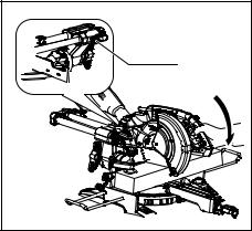
vagnen förs längs hela vägsträckan. Om klingan kommer i kontakt med glidkåpan kan det leda till bakkast eller oväntad rörelse för materialet och allvarlig personskada.
Fig.31
 FÖRSIKTIGT!
•För det skjutbara anhållet till vänster och fäst det såsom visas i figuren vid vinkelsågning. I annat fall kommer det i kontakt med klingan eller en del av maskinen, vilket kan leda till allvarliga skador på användaren.
Maskinen är utrustad med det skjutbara anhållet vilket vanligen ska placeras såsom visas i figuren.
Vid vänsterställd vinkelsågning ska det dock ställas in i det vänstra läget, såsom visas i figuren, om maskinhuvudet kommer i kontakt med det.
Glöm inte att flytta tillbaka det skjutbara anhållet till dess ursprungliga läge och fäst det genom att dra åt låsskruven hårt när vinkelsågningen är klar.
Vertikal tving
Fig.32
Den vertikala tvingen kan monteras antingen på vänster eller höger sida om anhållet. Sätt i tvingens fäststav i hålet på anhållet och dra åt skruven på anhållets baksida för att fästa tvingens fäststav.
Sätt tvingarmen i läge så att den passar till arbetsstyckets tjocklek och form och fäst den sedan genom att dra åt skruven. Om skruven som fäster tvingarmen kommer i kontakt med anhållet måste den flyttas till tvingarmens andra sida. Se till att ingen del av maskinen kommer i kontakt med tvingen när maskinhandtaget sänks till sin lägsta position eller när vagnen skjuts framåt eller dras bakåt hela vägen. Om någon del kommer i kontakt med tvingen monterar du om den.
Tryck arbetsstycket plant mot anhållet och geringsskivan. Placera arbetsstycket i önskat sågläge och fäst det stadigt genom att dra åt tvingens ratt.
 VARNING!
•Arbetsstycket måste fästas säkert mot geringsskivan och anhållet med tvingen under all drift. Om arbetsstycket inte är korrekt fastsatt mot anhållet kan arbetsstycket röra sig under sågarbetet och orsaka möjlig skada på klingan och att arbetsstycket kastas iväg samt att du förlorar kontroll över maskinen vilket leder till allvarlig personskada.
Hållare
Fig.33
Hållarna kan monteras på endera sidan för att på ett praktiskt och bekvämt sätt hålla arbetsstyckena horisontellt. Skjut in hållarens fäststavar helt i hålen i sågbordet. Fäst sedan hållarna ordentligt med skruvarna.
 VARNING!
•Stöd alltid ett långt arbetsstycke så att det är på samma nivå som geringsskivans ovansida för att få ett exakt sågresultat och för att förhindra att du förlorar kontrollen över maskinen. Med korrekt stöd av arbetsstycket undviker du att klingan nyper fast och eventuellt orsakar ett BAKÅTKAST vilket kan resultera i allvarlig personskada.
ANVÄNDNING
OBS:
•Se till att lösgöra handtaget från dess nedsänkta läge genom att dra ut låstappen.
•Tryck inte för mycket på handtaget vid sågningen. Detta kan leda till att motorn överbelastas och/eller försämrad sågning. Tryck ner handtaget endast så mycket som behövs för att sågningen ska löpa smidigt utan att klingans hastighet minskar påtagligt.
•Tryck försiktigt ner handtaget för att såga. Om handtaget trycks ner hårt eller i sidled kommer klingan att vibrera vilket ger sågmärken i arbetsstycket samtidigt som sågprecisionen försämras.
•Vid skjutsågning skall vagnen försiktigt tryckas mot anhållet utan att stoppa. Om vagnens rörelser upphör under sågningen lämnas ett märke på arbetsstycket och precisionen i snittet minskar.
 VARNING!
•Kontrollera att inte klingan är i kontakt med arbetsstycket eller något annat innan sågen sätts på.
I annat fall kan det leda till bakåtkast och allvarlig personskada.
1.Sågning genom tryck (sågning av små arbetsstycken)
1 |
1. Låsskruv |
014290 |
29
Arbetsstycken upp till 90 mm höga och 60 mm breda kan kapas på följande sätt.
Tryck vagnen fullständigt mot anhållet och dra åt låsskruven medurs för att fästa vagnen. Fäst arbetsstycket rätt med passande sorts tving. Starta maskinen utan att klingan har kontakt med arbetsstycket och vänta tills klingan har uppnått full hastighet innan du sänker ner den. Sänk sedan handtaget försiktigt tills det har sänkts helt, för att såga arbetsstycket. Stäng av maskinen när sågningen är avslutad och VÄNTA TILLS KLINGAN HAR STANNAT FULLSTÄNDIGT, innan klingan återförs till sitt helt uppfällda läge.
 VARNING!
•Dra åt ratten ordentligt medurs så att vagnen inte rör sig under användningen. I annat fall kan det leda till bakåtkast vilket kan orsaka allvarlig personskada som följd.
•Såga aldrig så små arbetsstycken att de inte kan fästas ordentligt med tvingen. Ett felaktigt fastsatt arbetsstycke kan orsaka bakåtkast och allvarliga personskador.
2.Sågning genom skjutning (sågning av breda arbetsstycken)
1 |
1. Låsskruv |
014291 |
Lossa låsskruven moturs så att vagnen kan skjutas fritt. Fäst arbetsstycket med rätt sorts tving. Dra vagnen mot dig helt och hållet. Starta maskinen utan att klingan vidrör arbetsstycket och vänta tills klingan uppnår full hastighet. Tryck ner handtaget och SKJUT VAGNEN MOT ANHÅLLET FÖR ATT SÅGA IGENOM ARBETSSTYCKET. Stäng av maskinen när sågningen är avslutad och VÄNTA TILLS KLINGAN HAR STANNAT FULLSTÄNDIGT innan klingan återförs till sitt helt uppfällda läge.
 VARNING!
•Vid skjutsågning ska du först dra vagnen fullständigt mot dig och trycka ner handtaget till dess helt nedsänkta läge. Skjut sedan vagnen mot anhållet. Börja aldrig sågningen om vagnen inte är dragen fullständigt mot dig.
Om skjutsågning utförs utan att du dragit vagnen helt mot dig kan ett bakåtkast uppstå med risk för allvarlig personskada.
•Försök aldrig att utföra en skjutsågning genom att dra vagnen mot dig. Att dra vagnen mot dig medan du sågar kan orsaka bakåtkast vilket resulterar i möjlig personskada.
•Utför aldrig skjutsågning med handtaget låst i det nedsänkta läget.
•Lossa aldrig på låsskruven som fäster vagnen medan klingan roterar. Om vagnen är lös medan du sågar kan det orsaka ett bakåtkast vilket kan resultera i allvarlig personskada.
3.Geringssågning
Se avsnittet "Inställning av geringsvinkeln" som förklarats tidigare.
4.Vinkelsågning
Fig.34
Lossa spaken och luta sågklingan till den önskade vinkeln (se avsnittet "Inställning av vinkeln för vinkelsågning" som beskrivits tidigare). Se till att spaken dras åt ordentligt för att fästa sågen säkert i den valda vinkeln. Fäst arbetsstycket med en tving. Kontrollera att vagnen har dragits tillbaka så långt det går mot användaren. Starta maskinen utan att klingan vidrör arbetsstycket och vänta tills klingan uppnår full hastighet. Sänk sedan handtaget försiktigt till dess helt nedsänkta läge medan tryck parallellt med klingan anläggs och SKJUT VAGNEN MOT ANHÅLLET FÖR ATT SÅGA ARBETSSTYCKET. Stäng av maskinen när sågningen är avslutad och VÄNTA TILLS KLINGAN HAR STANNAT FULLSTÄNDIGT innan klingan återförs till sitt helt uppfällda läge.
 VARNING!
•Efter inställning av klingan för vinkelsågning och innan du börjar arbeta med maskinen, ska du se till att vagnen och klingan har fri väg genom hela skäret. Vagnseller klingavbrott under sågningen kan orsaka bakåtkast och allvarlig personskada.
•Håll händerna borta från klingans såglinje när du utför en vinkelsågning. Klingans vinkel och den verkliga såglinjen kan förvirra användaren under sågningen och kontakt med klingan orsakar allvarlig personskada.
•Klingan ska aldrig lyftas förrän den har stannat helt. Under vinkelsågning kan det avsågade stycket ligga kvar mot klingan. Om klingan lyfts
30
 Loading...