


Linear Technology LTC1061MJ, LTC1061AMJ, LTC1061ACN, LTC1061ACJ, LTC1061 Datasheet
...
FEATURES
■Up to 6th Order Filter Functions with a Single 20-Pin 0.3" Wide Package
■Center Frequency Range up to 35kHz
■fO × Q Product up to 1MHz
■Guaranteed Center Frequency and Q Accuracy Over Temperature
■Guaranteed Low Offset Voltages Over Temperature
■90dB Signal-to-Noise Ratio
■Filter Operates from Single 4.7V Supply and up to
±8V Supplies
■Guaranteed Filter Specifications with ±5V Supply and
±2.37V Supply
■Low Power Consumption with Single 5V Supply
■Clock Inputs T2L and CMOS Compatible
APPLICATIOUS
■High Order, Wide Frequency Range Bandpass, Lowpass, Notch Filters
■Low Power Consumption, Single 5V Supply, Clock-Tunable Filters
■Tracking Filters
■Antialiasing Filters
LTCMOSTM is a trademark of Linear Technology Corp.
LTC1061
High Performance Triple
Universal Filter Building Block
DESCRIPTIOU
The LTC1061 consists of three high performance, universal filter building blocks. Each filter building block together with an external clock and 2 to 5 resistors can produce various second order functions which are available at its three output pins. Two out of three always provide lowpass and bandpass functions while the third output pin can produce highpass or notch or allpass. The center frequency of these functions can be tuned with an external clock or an external clock and a resistor ratio. For Q < 5, the center frequency ranges from 0.1Hz to 35kHz. For Qs of 10 or above, the center frequency ranges from 0.1Hz to 28kHz.
The LTC1061 can be used with single or dual supplies ranging from ±2.37V to ±8V (or 4.74V to 16V). When the filter operates with supplies of ±5V and above, it can handle input frequencies up to 100kHz.
The LTC1061 is compatible with the LTC1059 single universal filter and the LTC1060 dual. Higher than 6th order functions can be obtained by cascading the LTC1061 with the LTC1059 or LTC1060. Any classical filter realization can be obtained.
TheLTC1061ismanufacturedbyusingLinearTechnology’s enhanced LTCMOSTM silicon gate process.
TYPICAL APPLICATIOU
6th Order, Clock-Tunable, 0.5dB Ripple Chebyshev BP Filter
9.31k |
1k |
1 |
20 |
|
|
|
|
|
|
||
|
165k |
2 |
19 |
78.7k |
|
|
|
|
|
||
|
4.99k |
3 |
18 |
4.99k |
|
|
|
|
|
||
165k |
|
4 |
17 |
23.7k |
|
VIN < 100kHz |
|
|
|
||
|
5 |
16 |
|
|
|
|
|
|
49.9k |
||
|
|
LTC1061 |
15 |
|
|
|
|
6 |
V– = –7.5V |
|
|
|
|
|
|
|
|
7.5V |
|
7 |
14 |
4.99k |
|
|
|
|
|||
|
|
|
165k |
|
|
T2 CLK IN < 1.2MHz |
|
8 |
13 |
|
|
|
5.49k |
|
|||
|
|
9 |
12 |
|
|
|
|
|
|
||
V+ = 7.5V |
|
10 |
11 |
VOUT |
|
|
|
|
|
1061 TA01 |
Amplitude Response
|
|
2kHz |
|
|
fCLK = 1MHz |
|
|
0 |
|
|
|
|
|
|
|
|
|
|
|
|
|
–20 |
|
|
|
|
|
(dB) |
–40 |
|
|
|
|
|
GAIN |
|
|
|
|
|
|
|
|
|
|
|
|
|
FILTER |
–60 |
|
|
|
|
|
|
|
|
|
|
|
|
|
–80 |
|
|
|
|
|
|
–100 |
10 |
20 |
30 |
40 |
50 |
|
0 |
|||||
|
|
INPUT FREQUENCY GAIN (kHz) |
|
|||
|
|
|
|
|
|
LTC1061 • TA02 |
1
LTC1061
ABSOLUTE WAXIWUW RATIUGS
Supply Voltage ....................................................... |
|
18V |
Power Dissipation............................................. |
|
500mW |
Operating Temperature Range |
–40°C ≤ TA ≤ 85°C |
|
LTC1061AC, LTC1061C ............ |
||
LTC1061AM, LTC1061M ......... |
–55°C ≤ TA ≤ 125°C |
|
Storage Temperature Range ................ |
|
–65 ° C to 150°C |
Lead Temperature (Soldering, 10 sec.) |
................ 300°C |
|
PACKAGE/ORDER IUFORWATIOU
|
|
TOP VIEW |
|
|
|
ORDER PART |
|
|
|
|
|
|
NUMBER |
LPA |
1 |
|
|
20 |
LPB |
|
|
|
|
|
|
BPB |
|
|
|
|
|
|
|
|
BPA |
2 |
|
|
19 |
|
|
|
|
|
|
|
NB |
LTC1061AMJ |
NA |
3 |
|
|
18 |
||
|
|
|
|
|
INVB |
|
INVA |
4 |
|
|
17 |
LTC1061MJ |
|
|
|
|
|
|
S1B |
|
S1A |
5 |
|
|
16 |
LTC1061ACJ |
|
|
|
|
|
|
V – |
|
AGND |
6 |
|
|
15 |
LTC1061CJ |
|
|
|
|
|
|
|
|
50/100/HOLD |
7 |
|
|
14 |
LPC |
|
|
|
LTC1061ACN |
||||
|
|
|
|
|
|
|
CLK |
8 |
|
|
13 |
BPC |
|
|
|
LTC1061CN |
||||
|
|
|
|
|
|
|
LSh |
9 |
|
|
12 |
HPC |
|
|
|
LTC1061CS |
||||
V+ |
|
|
|
|
INVC |
|
10 |
|
|
11 |
|||
|
|
|
|
|
||
J PACKAGE |
N PACKAGE |
|
||||
20-LEAD CERAMIC DIP 20-LEAD PLASTIC DIP |
|
|||||
|
|
S PACKAGE |
|
|
|
|
|
20-LEAD PLASTIC SOL |
|
|
|||
TJMAX = 125°C, θJA = 100°C/W (J)
TJMAX = 100°C, θJA = 100°C/W (N)
TJMAX = 100°C, θJA = 85°C/W (S)
Consult factory for Industrial grade parts
ELECTRICAL CHARACTERISTICS
(Complete Filter)V = ±5V, T |
A |
= 25°C, T2L clock input level, unless otherwise specified. |
|
|
|
|
||
S |
|
|
|
|
|
|
|
|
PARAMETER |
|
|
CONDITIONS |
|
MIN |
TYP |
MAX |
UNITS |
Center Frequency Range, fO |
|
|
fO × Q ≤ 175kHz, Mode 1, VS = ±7.5V |
|
|
0.1–35k |
|
Hz |
|
|
|
fO × Q ≤ 1.6MHz, Mode 1, VS = ±7.5V |
|
|
0.1–25k |
|
Hz |
|
|
|
fO × Q ≤ 75kHz, Mode 3, VS = ±7.5V |
|
|
0.1–25k |
|
Hz |
|
|
|
fO × Q ≤ 1MHz, Mode 3, VS = ±7.5V |
|
|
0.1–17k |
|
Hz |
Input Frequency Range |
|
|
|
|
|
0–200k |
|
Hz |
|
|
|
|
|
|
|
||
Clock-to-Center Frequency Ratio, fCLK/fO |
Sides A, B: Mode 1, R1 = R3 = 50k |
|
|
|
50 ±0.6% |
|
||
LTC1061A |
|
|
R2 = 5k, Q = 10, fCLK = 250kHz |
● |
|
|
|
|
LTC1061 |
|
|
Pin 7 High. |
● |
|
|
50 ±1.2% |
|
|
|
|
Side C: Mode 3, R1 = R3 = 50k |
|
|
|
|
|
|
|
|
R2 = R4 = 5k, fCLK = 250kHz |
|
|
|
100 ±0.6% |
|
LTC1061A |
|
|
Same as Above, Pin 7 at |
● |
|
|
|
|
LTC1061 |
|
|
Mid-Supplies, fCLK = 500kHz |
● |
|
|
100 ±1.2% |
|
Clock-to-Center Frequency Ratio, |
|
|
|
|
|
|
|
|
Side-to-Side Matching |
|
|
|
|
|
|
|
|
LTC1061 |
|
|
|
|
|
|
1.2% |
|
|
|
|
|
|
|
|
|
|
Q Accuracy |
|
|
Sides A, B, Mode 1 |
|
|
± 2 |
5 |
% |
LTC1061A |
|
|
Side C, Mode 3 |
● |
|
|||
LTC1061 |
|
|
fO × Q ≤ 50kHz, fO × ≤ 5kHz |
● |
|
±3 |
5 |
% |
fO Temperature Coefficient |
|
|
Mode 1, 50:1, fCLK < 300kHz |
|
|
±1 |
|
ppm/°C |
Q Temperature Coefficient |
|
|
Mode 1, 100:1, fCLK < 500kHz |
|
|
±5 |
|
ppm/°C |
|
|
|
Mode 3, fCLK < 500kHz |
|
|
±5 |
|
ppm/°C |
2

LTC1061
ELECTRICAL CHARACTERISTICS
(Complete Filter)VS = ±5V, TA = 25°C, T2L clock input level, unless otherwise specified.
PARAMETER |
CONDITIONS |
|
MIN |
TYP |
MAX |
UNITS |
DC Offset Voltage |
|
|
|
|
|
|
VOS1, Figure 23 |
|
● |
|
2 |
15 |
mV |
VOS2 |
fCLK = 250kHz, 50:1 |
● |
|
3 |
30 |
mV |
VOS2 |
fCLK = 500kHz, 100:1 |
● |
|
6 |
60 |
mV |
VOS3, LTC1061CN, ACN/LTC1061CS |
fCLK = 250kHz, 50:1 |
● |
|
3 |
20/25 |
mV |
VOS3, LTC1061CN, ACN/LTC1061CS |
fCLK = 500kHz, 100:1 |
● |
|
6 |
40/50 |
mV |
Clock Feedthrough |
fCLK < 1MHz |
|
|
0.4 |
|
mVRMS |
Maximum Clock Frequency |
Mode 1, Q < 5, VS ³ ±5 |
|
|
2.5 |
|
MHz |
Power Supply Current |
|
|
6 |
8 |
11 |
mA |
|
|
● |
|
|
15 |
mA |
|
|
|
|
|
|
|
(Complete Filter)VS = ±2.37V, TA = 25°C, unless otherwise specified.
Center Frequency Range, fO |
fO ´ Q £ 120kHz, Mode 1, 50:1 |
|
0.1– 12k |
|
Hz |
|
|
fO ´ Q £ 120kHz, Mode 3, 50:1 |
|
0.1– 10k |
|
Hz |
|
Input Frequency Range |
|
|
0 – 20k |
|
Hz |
|
|
|
|
|
|
|
|
Clock-to-Center Frequency Ratio |
50:1, fCLK = 250kHz, Q = 10 |
|
|
±0.6% |
|
|
LTC1061A |
Sides A, B: Mode 1 |
|
50 |
|
|
|
LTC1061 |
Side C, Mode 3, 250kHz |
|
50 |
±1.0% |
|
|
LT1061A |
100:1, fCLK = 500kHz, Q = 10 |
|
100 |
±0.6% |
|
|
LT1061 |
Sides A, B: Mode 1 |
|
100 |
±1.0% |
|
|
|
Side C: Mode 3 |
|
|
|
|
|
|
|
|
|
|
|
|
Q Accuracy |
|
|
|
±2 |
|
|
LTC1061A |
Same as Above |
|
|
|
% |
|
LTC1061 |
|
|
|
±3 |
|
% |
|
|
|
|
|
|
|
Maximum Clock Frequency |
|
|
700 |
|
kHz |
|
|
|
|
|
|
|
|
Power Supply Current |
|
|
|
4.5 |
6 |
mA |
|
|
|
|
|
|
|
(Internal Op Amps) TA = 25°C, unless otherwise specified.
Supply Voltage Range |
|
|
±2.37 |
|
±9 |
V |
|
|
|
|
|
|
|
Voltage Swings |
VS = ±5V, RL = 5k (Pins 1,2,13,14,19,20) |
|
±4.0 |
±4.2 |
|
V |
LTC1061A |
|
|
||||
LTC1061 |
VS = ±5V, RL = 3.5k (Pins 3,12,18) |
|
±3.8 |
±4.2 |
|
V |
LTC1061, LTC1061A |
|
● |
±3.6 |
|
|
V |
|
|
|
|
|
|
|
Output Short-Circuit Current |
VS = ±5V |
|
|
|
|
|
Source/Sink |
|
|
40/3 |
|
mA |
|
|
|
|
|
|
|
|
DC Open-Loop Gain |
VS = ±5V, RL = 5k |
|
|
80 |
|
dB |
GBW Product |
VS = ±5V |
|
|
3 |
|
MHz |
Slew Rate |
VS = ±5V |
|
|
7 |
|
V/ms |
The ● denotes the specifications which apply over the full operating temperature range.
3
LTC1061
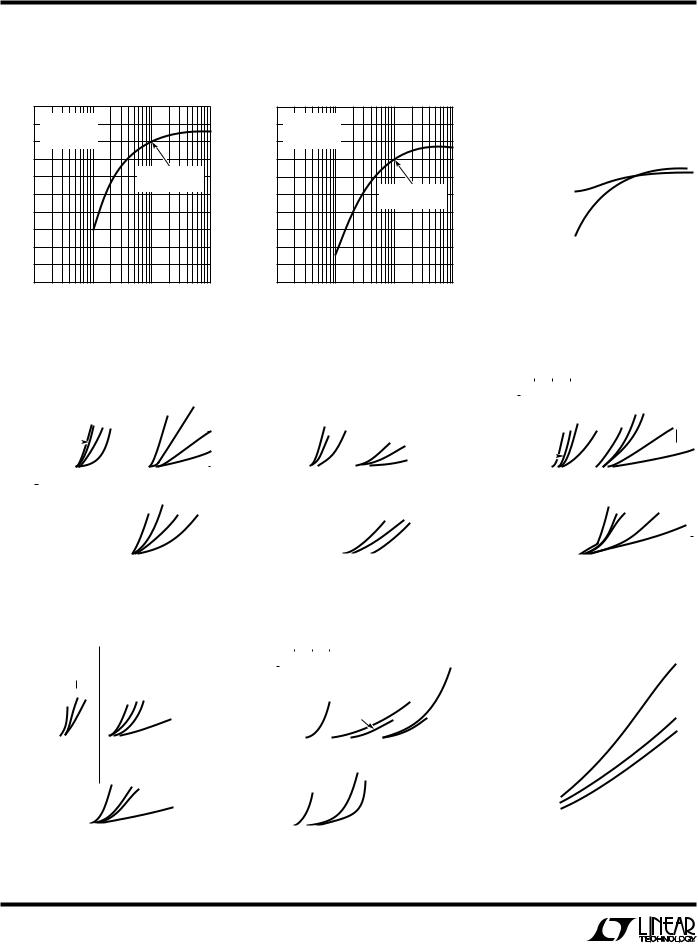
TYPICAL PERFORWAUCE CHARACTERISTICS
Mode 1, Mode 3 (fCLK/fO) |
Mode 1, Mode 3 (fCLK/fO) |
Deviation vs Q |
Deviation vs Q |
|
0.4 |
VS = ±5V |
|
|
|
|
VS = ±5V |
|
|
|
|
TA = 25°C |
|
|
|
|
TA = 25°C |
|
|
) |
0 |
fCLK = 250kHz |
|
|
|
0.1 |
fCLK = 500kHz |
|
|
|
|
|
|
) |
|
|
|
|
|
O |
–0.4 |
|
|
|
O |
.0 |
|
|
|
/f |
|
|
|
/f |
|
|
|
||
CLK |
–0.8 |
|
fCLK/fO = |
|
CLK |
–0.1 |
|
|
|
(f |
|
50 (TEST POINT) |
|
(f |
|
|
|
||
DEVIATION |
–1.2 |
|
|
DEVIATION |
–0.2 |
|
fCLK/fO = |
||
|
|
|
|
||||||
|
–1.6 |
|
|
|
|
–0.3 |
|
100 (TEST POINT) |
|
|
|
|
|
|
|
|
|
||
% |
–2.0 |
|
|
|
% |
–0.4 |
|
|
|
|
|
|
|
|
|
|
|
||
|
–2.4 |
|
|
|
|
–0.5 |
|
|
|
|
|
|
|
|
|
–0.6 |
|
|
|
|
0.1 |
1 |
10 |
100 |
|
0.1 |
1 |
10 |
100 |
|
|
|
IDEAL Q |
|
|
|
|
IDEAL Q |
|
|
|
|
LTC1061 G01 |
|
|
|
|
LTC1061 G02 |
|
Mode 3: Deviation of (fCLK/fO) with Respect to Q = 10 Measurement
|
|
|
|
|
|
|
|
|
|
|
|
|
|
|
|
|
|
|
|
|
|
|
|
|
|
|
|
|
|
|
|
|
|
TO |
|
|
|
VS = ±5V |
|
|
|
|
|
|
|
|
|
|
|
|
|
|
|
|
|
|
|
|
|
||||||||
RESPECT |
(%) |
0.1. |
|
TA = 25°C |
|
|
|
|
|
|
|
|
|
|
|
|
|
|
|
|
|
|
|
|
|
||||||||
|
PIN 7 AT 100:1 |
|
|
|
|
|
|
|
|
|
|
|
|
|
|
|
|
|
|
|
|
|
|||||||||||
|
|
|
|
|
|
|
|
|
|
|
|
|
|
|
|
|
|
|
|
|
|
|
|
|
|||||||||
|
|
|
|
|
|
|
|
|
|
|
|
|
|
|
|
fCLK/fO = 500:1 |
|
|
|
|
|
|
|
||||||||||
|
|
|
|
|
|
|
|
|
|
|
|
|
|||||||||||||||||||||
DEVIATIONfOF |
MEASUREMENT10=Q |
|
|
|
|
|
|
|
|
|
|
|
|
|
|
ÖR2/R4 = 1/5 |
|
|
|
|
|
|
|
|
|||||||||
|
|
|
|
|
|
|
|
|
|
|
|
|
|
|
|
|
|
|
|
|
|
|
|
|
|
|
|
|
|
|
|
||
WITH |
|
0 |
|
|
|
|
|
|
|
|
|
(A) |
|
|
|
|
|
|
|
|
|
|
|
|
|
|
|
|
|
|
|
|
|
O |
|
–0.1 |
|
|
|
|
|
|
|
|
|
|
|
|
|
|
|
|
|
|
|
|
|
|
|
|
|
|
|
|
|
|
|
/f |
|
|
|
|
|
|
|
|
|
|
|
|
|
|
|
|
|
|
|
|
|
|
|
|
|
|
|
|
|
|
|
|
|
CLK |
|
|
|
|
|
|
|
|
|
|
|
|
|
|
|
|
|
|
|
|
|
|
|
|
|
|
|
|
|
|
|
|
|
|
–0.2 |
|
|
|
|
|
|
|
|
|
|
|
|
|
ÖR2/R4 = 1/2 |
|
|
|
|
|
|
|
|||||||||||
|
|
|
|
|
|
|
|
|
|
|
|
|
|
|
|
|
|
|
|
|
|||||||||||||
|
|
|
|
|
|
|
|
|
|
|
|
|
|
|
|
|
|
|
|
|
|
||||||||||||
|
|
–0.3 |
|
|
|
|
|
|
|
|
|
|
|
|
|
fCLK/fO = 200:1 |
|
|
|
|
|
|
|
||||||||||
|
|
|
|
|
|
|
|
|
|
|
(B) |
|
|
|
|
|
|
|
|
|
|
|
|
|
|
|
|
|
|
|
|
||
|
|
–0.4 |
|
|
|
|
|
|
|
|
|
|
|
|
|
|
|
|
|
|
|
|
|
|
|
|
|
|
|
|
|
||
|
|
|
|
|
|
|
|
|
|
|
|
|
|
|
|
|
|
|
|
|
|
|
|
|
|
|
|
|
|
|
|
|
|
|
|
|
|
|
|
|
|
|
|
|
|
|
|
|
|
|
|
|
|
|
|
|
|
|
|
|
|
|
|
|
|
|
|
|
|
–0.5 |
|
|
|
|
|
|
|
|
|
|
|
|
|
|
|
|
|
|
|
|
|
|
|
|
|
|
|
|
|
|
|
|
|
|
|
|
|
|
|
|
|
|
|
|
|
|
|
|
|
|
|
|
|
|
|
|
|
|
|
|
|
|
|
|
|
|
|
|
|
|
|
|
|
|
|
|
|
|
|
|
|
|
|
|
|
|
|
|
|
|
|
|
|
|
|
|
|
|
|
0.1 1 10 100 IDEAL Q
LTC1061 G03
Mode 1: (fCLK/fO) = 50:1
|
|
|
|
|
TA = 25°C |
|
|
|
|
|
|
|
|
|
|
|
|
|
|
|
|
|
|
|
|
|
|
|
|
|
|
|
|
VS = ±7.5V |
|
|
|
|||||||||||||||||||||
(%)Q |
|
|
|
|
fCLK/fO = 50/1 |
|
|
|
|
|
|
|
|
|
|
|
|
|
|
|
|
|
|
|
|
|
|
|
|
|
|
|
|
|
|
|
|
|
|
|
20 |
|
|
|
||||||||||||||
|
|
|
|
|
|
|
|
|
|
|
|
|
|
|
|
|
|
|
|
|
|
|
|
|
|
|
|
|
|
|
|
|
|
|
|
|
|
|
|
|
|
|
|
|
|
|
|
|
|
|
|
|
|
|
||||
|
|
|
|
|
|
|
|
|
|
|
|
|
|
|
|
|
|
|
10 |
|
|
|
|
|
|
|
|
|
|
|
|
|
|
|
|
|
|
|
|
|
|
|
|
|
|
|
|
|
|
|
||||||||
|
|
|
|
|
|
|
|
|
|
|
|
|
|
|
|
|
|
|
|
|
|
|
|
|
|
|
|
|
|
|
|
|
|
|
|
|
|
|
|
|
|
|
|
|
|
|
|
|
|
|
|
|||||||
|
30 |
|
|
|
|
|
|
|
|
|
|
|
|
VS = ±2.5V |
|
|
|
|
|
|
|
|
|
|
|
|
|
|
|
50 |
|
|
|
|
|
|
|
|
|
|
|
|
|
|
||||||||||||||
|
|
|
|
|
|
|
|
|
|
|
|
|
|
|
|
|
|
|
|
|
|
|
|
|
|
|
|
|
|
|
|
|
|
|
|
|
|
|
|
|
|
|
||||||||||||||||
|
|
|
|
|
|
|
|
|
|
|
|
|
|
|
|
|
|
|
|
|
|
|
|
|
|
|
|
|
|
|
|
|
|
|
|
|
|
|
|
|
|
|
|
|
|
|
|
|
|
|
|
|
|
|
|
|
|
|
IDEAL |
20 |
|
|
|
|
|
|
|
|
|
|
|
|
|
50 |
|
|
|
|
|
|
|
|
|
|
|
|
|
|
|
|
|
|
|
|
|
|
|
|
|
|
|
|
|
|
|
|
|
|
|
|
|
10 |
|
|
|||
10 |
|
|
|
|
|
|
|
|
|
|
|
|
|
|
|
|
|
|
|
|
|
|
|
Q<5 |
|
|
|
|
|
|
|
|
|
|
|
|
|
|
|
|
|
|
|
|
|
|
|
|
|
|
|
|
|
|
||||
FROM |
|
|
|
|
|
|
|
|
|
20 |
|
|
|
|
|
|
|
|
|
|
|
|
|
|
|
|
|
|
|
|
|
|
|
|
|
|
|
|
|
|
|
|
|
|
|
|
|
|
|
|
|
|
||||||
|
|
|
|
|
|
|
|
|
|
|
|
|
|
|
|
|
|
|
|
|
|
|
|
|
|
|
|
|
|
|
|
|
|
|
|
|
|
|
|
|
|
|
|
|
|
|
|
|
|
|
|
|
|
|
||||
|
|
|
|
|
|
|
|
|
|
|
|
|
|
|
|
|
|
|
|
|
|
|
|
|
|
|
|
|
|
|
|
|
|
|
|
|
|
|
|
|
|
|
|
|
|
|
|
|
|
|
|
|
|
|
|
|
|
|
0 |
|
|
|
|
|
|
|
|
|
|
|
|
|
|
|
|
|
|
|
|
|
|
|
|
|
|
|
|
|
|
|
|
|
|
|
|
|
|
|
|
|
|
|
|
|
|
|
|
|
|
|
Q<5 |
|
|||||
|
|
|
|
|
|
|
|
|
|
|
|
|
|
|
|
|
|
|
|
|
|
|
|
|
|
|
|
|
|
|
|
|
|
|
|
|
|
|
|
|
|
|
|
|
|
|
|
|
|
|
|
|
||||||
|
|
|
|
|
TA = 25°C |
|
|
|
|
|
|
|
|
|
|
|
|
|
|
|
|
|
|
|
|
|
|
|
|
|
|
|
|
|
|
|
|
|
|
|
|
|
|
|
|
|
|
|
|
|
||||||||
DEVIATION |
|
|
|
|
|
|
|
|
|
|
|
|
|
|
|
|
|
|
|
|
|
|
|
|
|
|
|
|
|
|
|
VS = |
±5V |
|
|
|
|
|
|
|||||||||||||||||||
20 |
|
|
|
fCLK/fO = 50/1 |
|
|
|
|
|
|
|
|
|
|
|
|
|
|
|
|
|
|
|
|
|
|
|
|
|
|
|
|
||||||||||||||||||||||||||
|
|
|
|
|
|
|
|
|
|
|
|
|
|
|
|
|
|
|
|
|
|
|
|
|
|
|
|
|
||||||||||||||||||||||||||||||
|
|
|
|
|
|
|
|
|
|
|
|
|
|
|
|
|
|
|
|
|
|
|
|
|
|
|
|
|
|
|
|
|
|
|
|
|
|
|
|
|
|
|
|
|
|
|
|
|
|
|
|
|
|
|
|
|
||
|
30 |
|
|
|
|
|
|
|
|
|
|
|
|
|
|
|
|
|
|
|
|
|
|
|
|
|
|
|
|
|
|
|
|
|
|
|
|
|
|
20 |
|
|
|
|
|
|
|
|
|
|
|
|
|
|
|
|||
|
|
|
|
|
|
|
|
|
|
|
|
|
|
|
|
|
|
|
|
|
|
|
|
|
|
|
|
|
|
|
|
|
|
|
|
|
|
|
|
|
|
|
|
|
|
|
|
|
|
|
|
|
||||||
|
|
|
|
|
|
|
|
|
|
|
|
|
|
|
|
|
|
|
|
|
|
|
|
|
|
|
|
|
|
|
|
|
|
|
50 |
|
|
|
|
|
|
|
|
|
|
|
|
|
|
|
|
|
|
|
|
|
||
|
10 |
|
|
|
|
|
|
|
|
|
|
|
|
|
|
|
|
|
|
|
|
|
|
|
|
|
|
|
|
|
|
|
|
|
|
|
|
|
|
|
|
10 |
|
|
|
Q<5 |
|
|
|
|||||||||
|
|
|
|
|
|
|
|
|
|
|
|
|
|
|
|
|
|
|
|
|
|
|
|
|
|
|
|
|
|
|
|
|
|
|
|
|
|
|
|
|
|
|
|
|
|
|
|
|
|
|
|
|
|
|
|
|
|
|
|
|
|
|
|
|
|
|
|
|
|
|
|
|
|
|
|
|
|
|
|
|
|
|
|
|
|
|
|
|
|
|
|
|
|
|
|
|
|
|
|
|
|
|
|
|
|
|
|
|
|
|
|
|
|
|
|
|
|
|
|
|
|
|
|
|
|
|
|
|
|
|
|
|
|
|
|
|
|
|
|
|
|
|
|
|
|
|
|
|
|
|
|
|
|
|
|
|
|
|
|
|
|
|
|
|
|
|
|
|
|
|
|
|
|
|
||
|
0 |
|
|
|
|
|
|
|
|
|
|
|
|
|
|
|
|
|
|
|
|
|
|
|
|
|
|
|
|
|
|
|
|
|
|
|
|
|
|
|
|
|
|
|
|
|
|
|
|
|
|
|
|
|
|
|
|
|
|
|
|
4 |
|
|
8 |
|
12 |
16 |
20 |
|
|
24 |
28 |
|
|
32 |
36 |
40 |
|||||||||||||||||||||||||||||||||||||||
|
0 |
|
|
|
|
|
|
|
|
|||||||||||||||||||||||||||||||||||||||||||||||||
|
|
|
|
|
|
|
|
|
|
|
|
CENTER FREQUENCY (kHz) |
|
|
|
|
|
|
|
|
|
|
||||||||||||||||||||||||||||||||||||
|
|
|
|
|
|
|
|
|
|
|
|
|
|
|
|
|
|
|
|
|
|
|
|
|
|
|
|
|
|
|
|
|
|
|
|
|
|
|
|
|
|
|
|
|
|
|
|
|
|
|
1061 G04 |
|||||||
|
|
Mode 3: (fCLK/fO) = 100:1 |
|
|
|
|
|
|
|
|
|
|
|
|
|
|
||||||||||||||||||||||||||||||||||||||||||
|
|
|
|
|
|
|
|
|
|
|
|
|
|
|
|
|
|
|
|
|
|
|
|
|
|
|
|
|
|
|
|
|
|
|
|
|
|
|
|
|
|
|
|
|
|
|
|
|
||||||||||
|
|
|
|
|
|
|
|
|
|
|
|
|
|
|
|
|
|
|
|
|
|
|
|
|
|
|
|
|
|
|
|
|
|
|
|
|
|
|
|
|
|
|
|
|
|
|
|
|
||||||||||
(%)Q |
30 |
|
|
|
|
|
VS = ±2.5V |
|
|
|
|
|
|
|
|
|
|
|
|
|
VS = ±7.5V |
|
|
|
|
|
|
|
|
|
|
|
||||||||||||||||||||||||||
|
|
|
|
|
|
|
|
|
10 |
|
|
|
|
|
|
|
|
|
|
|
|
|
|
|
|
|
|
|
|
|
|
|
|
|
|
|
|
|
|
|
|
|
|
|
|
|
|
|
|
|
|
|
||||||
|
|
|
|
|
|
|
|
|
|
|
|
|
|
|
|
|
|
|
|
|
|
|
|
|
|
|
|
|
|
|
|
|
|
|
|
|
|
|
|
|
|
|
|
|
|
|
|
|
|
|
|
|
|
|
|
|
|
|
|
|
|
|
|
|
|
|
|
|
|
|
|
|
|
|
|
|
|
|
|
|
|
|
|
|
|
|
|
|
|
|
|
|
|
|
|
|
|
|
|
|
|
|
|
|
|
|
|
|
|
|
|
|
|||||
|
|
|
|
|
|
|
|
|
|
|
|
|
|
|
|
|
|
|
|
|
|
|
|
|
|
|
|
|
|
|
|
|
|
|
|
|
|
|
|
|
|
|
|
|
|
|
|
|
|
|
|
|
|
|
|
|||
|
20 |
|
|
|
|
|
|
|
|
|
|
|
|
|
|
|
|
|
|
|
|
|
|
|
|
|
|
|
|
|
10 |
|
|
|
|
|
|
|
|
|
|
|
|
|
|
|
|
|
|
|
|
|
|
|||||
IDEAL |
|
|
|
|
|
|
|
|
|
|
|
|
|
|
|
|
|
|
|
|
|
|
|
|
|
|
|
|
|
|
|
|
Q=5 |
|
|
|
|
|
|
|
|
|
|
|
|
|
|
|
|
|
|
|||||||
|
|
|
|
|
|
|
|
|
|
|
|
|
|
|
|
|
|
|
|
|
|
|
|
|
20 |
|
|
|
|
|
|
|
|
|
|
|
|
|
|
|
|
|
|
|
|
|
|
|
|
|
|
|
|
|
|
|
||
10 |
|
|
|
|
Q=20 |
|
|
|
|
|
|
Q=5 |
|
|
|
|
|
|
|
|
|
|
|
|
|
|
|
|
|
|
|
|
|
|
|
Q=1 |
|
|
|
|
|
|
|
|
|
|||||||||||||
FROM |
0 |
|
|
|
|
|
|
|
|
|
|
|
|
|
|
|
|
|
|
|
|
|
|
|
|
|
|
|
|
|
|
|
|
|
|
|
|
|
|
|
|
|
|
|
|
|
||||||||||||
|
|
|
|
|
|
|
|
|
|
|
|
|
|
|
|
|
|
|
|
|
|
|
|
|
|
|
|
|
|
|
|
|
|
|
|
|
|
|
|
|
|
|
|
|
|
|
|
|
|
|
|
|
|
|
|
|
||
DEVIATION |
|
|
|
|
|
|
|
|
|
|
|
|
|
|
|
|
|
|
|
|
|
|
|
|
|
|
|
|
|
|
|
|
|
|
|
|
|
|
|
|
|
|
|
|
|
|
|
|
|
|
|
|
|
|
|
|
|
|
|
|
|
|
|
|
|
|
|
|
|
|
|
|
|
|
|
|
|
|
|
|
|
|
|
|
|
|
|
|
|
|
|
|
|
|
|
|
|
|
|
|
|
|
|
|
|
||||||||||||
20 |
|
|
|
|
|
|
|
|
|
|
|
|
|
|
|
|
Q=20 |
|
VS |
10 |
|
Q=5 |
|
|
|
|
|
|
|
|
|
|
|
|
|
|
|
|||||||||||||||||||||
|
30 |
|
|
|
|
|
|
|
|
|
|
|
|
|
|
|
|
|
|
|
|
|
|
|
|
|
|
|
|
|
|
|
|
|
|
|
|
|
|
|
|
|
|
|
|
|
|
|
|
|
|
|
|
|
|
|
|
|
|
10 |
|
|
|
|
|
|
|
|
|
|
|
|
|
|
|
|
|
|
|
|
|
|
|
|
|
|
|
|
|
|
|
|
|
|
|
|
|
|
|
|
|
|
|
|
|
|
|
|
|
|
|
|
|
|
|
|
|
|
|
|
|
|
|
|
|
|
|
|
|
|
|
|
|
|
|
|
|
|
|
|
|
|
|
|
|
|
|
|
|
|
|
|
|
|
|
|
|
|
|
|
|
|
|
|
|
|
|
|
|
|
|
|
|
|
|
|
|
|
|
|
|
|
|
|
|
|
|
|
|
|
|
|
|
|
|
|
|
|
|
|
|
|
|
|
|
|
|
|
|
|
|
|
|
|
|
|
|
|
|
|
|
|
|
|
|
|
|
|
|
||||||
|
|
|
|
|
|
|
|
|
|
|
|
|
|
|
|
|
|
|
|
|
|
|
|
|
|
|
|
|
|
|
|
|
|
|
|
|
|
|
|
|
|
|
|
|
|
|
|
|
|
|
|
|
|
|
|
|||
|
|
|
|
|
|
|
|
|
|
|
|
|
|
|
|
|
|
|
|
|
|
|
|
|
|
|
|
|
|
|
|
|
|
|
|
|
|
|
|
|
|
|
|
|
|
Q=1 |
|
|
|
|
|
|
|
|
|
|||
|
|
|
|
|
|
|
|
|
|
|
|
|
|
|
|
|
|
|
|
|
|
|
|
|
|
|
|
|
|
|
|
|
|
|
|
|
|
|
|
|
|
|
|
|
|
|
|
|
|
|||||||||
|
0 |
|
|
|
|
|
|
|
|
|
|
|
|
|
|
|
|
|
|
|
|
|
|
|
|
|
|
|
|
|
|
|
|
|
|
|
|
|
|
|
|
|
|
|
|
|
|
|
|
|
|
|
|
|
|
|
|
|
|
|
|
|
4 |
|
8 |
|
|
|
12 |
|
|
16 |
|
|
|
|
20 |
24 |
|
|
|
|
28 |
|
|
|
|
32 |
|||||||||||||||||||||||||||||
|
0 |
|
|
|
|
|
|
|
|
|
|
|
|
|
|
|
|
|
|
|
||||||||||||||||||||||||||||||||||||||
CENTER FREQUENCY (kHz)
1061 G07
Mode 1: (fCLK/fO) = 100:1
|
|
|
|
|
|
|
|
|
|
|
|
|
|
|
|
|
|
|
|
|
|
|
|
|
|
|
|
|
|
|
|
|
|
|
|
|
|
|
|
|
|
|
|
|
|
|
|
|
|
|
|
|
|
|
|
|
|
|
|
|
|
|
|
|
|
Q(%) |
30 |
|
|
|
VS = ±2.5V |
|
|
|
|
|
|
|
VS = ±7.5V |
|
|
|
|
|
|
|||||||||||||
|
|
|
|
|
|
|
|
|
|
|
|
|
|
|
||||||||||||||||||
20 |
|
|
|
|
|
|
|
|
|
|
|
|
|
|
|
|
|
|
|
|
|
|
|
|
|
|
|
|
|
|
|
|
IDEAL |
|
|
Q=20 |
|
10 |
|
|
Q<5 |
|
|
|
|
|
|
|
|
|
|
|
|
|
|
|
|
|
|
|
|
||||
|
|
|
|
|
|
|
|
|
|
Q=20 |
|
|
|
10 |
|
|
|
|
|
|
|
|||||||||||
10 |
|
|
|
|
|
|
|
|
|
|
|
|
|
|
|
|
|
|
|
|
|
|
|
|
|
|||||||
FROM |
|
|
|
|
|
|
|
|
|
|
|
|
|
|
|
|
|
|
|
|
|
|
|
|
|
|
|
|
|
|
|
|
|
|
|
|
|
|
|
|
|
|
|
|
|
|
|
|
|
|
|
|
|
|
|
|
|
|
|
|
|
|
|
|
|
|
|
|
|
|
|
|
|
|
|
|
|
|
|
|
|
|
|
|
|
|
|
|
|
|
|
|
|
|
|
|
||
|
|
|
|
|
|
|
|
|
|
|
|
|
|
|
|
|
|
|
|
|
|
|
|
|
|
|
|
|
|
|||
0 |
|
|
|
|
|
|
|
|
|
|
|
|
|
|
|
|
|
|
|
|
|
|
Q=5 |
|
|
|
|
|||||
|
|
|
|
|
|
|
|
|
|
|
|
|
|
|
|
|
|
|
|
|
|
|
|
|
|
|
|
|
|
|
||
|
|
|
|
|
|
|
|
|
|
|
|
|
|
|
|
|
|
|
|
|
|
|
|
|
|
|
|
|
|
|
|
|
DEVIATION |
20 |
|
|
|
|
|
|
|
|
|
|
|
|
|
|
|
|
|
|
|
|
|
|
|
|
|
|
|
|
|
|
|
|
|
|
|
|
|
|
|
|
|
|
|
|
|
|
|
|
|
|
|
|
|
|
|
|
|
|
|
|
||||
|
|
|
|
|
|
|
|
|
|
|
|
|
|
|
10 |
|
|
|
|
|
|
|
|
|
|
|||||||
|
30 |
|
|
|
|
|
|
|
|
|
|
|
|
|
VS = ±5V |
|
|
|
|
|
|
|
|
|
|
|
||||||
|
|
|
|
|
|
|
|
|
|
|
|
|
|
|
|
|
|
|
|
|
|
|
|
|
|
|
|
|
|
|
|
|
|
10 |
|
|
|
|
|
|
|
|
|
|
Q=20 |
|
|
|
|
|
|
|
|
Q=5 |
|
|
|
|
|||||||
|
|
|
|
|
|
|
|
|
|
|
|
|
|
|
|
|
|
|
|
|||||||||||||
|
|
|
|
|
|
|
|
|
|
|
|
|
|
|
|
|
|
|
|
|
|
|
|
|
|
|
|
|
|
|
|
|
|
|
|
|
|
|
|
|
|
|
|
|
|
|
|
|
|
|
|
|
|
|
|
|
|
|
|
|
|
|
|
|
|
|
0 |
|
|
|
|
|
|
|
|
|
|
|
|
|
|
|
|
|
|
|
|
|
|
|
|
|
|
|
|
|
|
|
|
4 |
8 |
12 |
16 |
|
20 |
|
|
24 |
|
|
|
32 |
28 |
||||||||||||||||||
|
0 |
|
|
|
|
|
|
|||||||||||||||||||||||||
CENTER FREQUENCY (kHz)
1061 G05
fCLK/fO vs fO
|
2.5 |
|
|
|
|
|
|
|
|
|
|
|
|
|
|
|
|
|
|
|
|
|
|
|
|
|
|
|
|
|
|
|
|
|
|
|
|
|
|
|
|
|
Q = 10 |
|
|
|
|
|
|
|
|
|
|
|
|
|
|
|
|
|
|
|
|
|
|
|
|
|
|
|
|
|
|
|
|
|
|
||||
|
|
|
|
|
|
|
|
|
|
|
|
|
|
|
|
|
|
|
|
|
|
|
|
|
|
VS |
= ±7.5V |
|
|
|
|
|||||||||
|
2.0 |
|
TA = 25°C |
|
|
|
|
|
|
|
|
|
|
|
|
|
|
|
|
|
|
|
|
|
|
|
|
|||||||||||||
|
|
|
|
|
|
|
|
|
|
|
|
|
|
|
|
|
|
|
|
|
|
|
|
|
||||||||||||||||
(%) |
|
|
fCLK/fO = 50/1 |
|
|
|
|
|
|
|
|
|
|
|
|
|
|
|
|
|
|
|
|
|
||||||||||||||||
1.5 |
|
|
|
|
VS = ±5V |
|
|
|
|
|
|
|
MODE |
1 |
|
|
|
|
||||||||||||||||||||||
|
|
|
|
|
|
|
|
|
|
|
|
|
|
|
|
|||||||||||||||||||||||||
O |
|
|
|
VS = ±2.5V |
|
|
|
|
|
|
|
|
|
|
|
|
|
|
|
|
|
|
|
|
|
|
|
|
|
|
|
|
|
|
|
|
||||
/f |
1.0 |
|
|
|
|
|
|
|
|
|
|
|
|
|
|
|
MODE 1 |
|
|
|
|
|
|
|
|
|
|
|
||||||||||||
CLK |
|
|
|
MODE 1, |
|
|
|
|
|
|
|
|
|
|
|
|
|
|
|
|
|
|
|
|
|
|
|
|
||||||||||||
|
|
|
|
|
|
|
|
|
|
|
|
|
|
|
|
|
|
|
|
|
|
|
|
|
|
|
|
|
|
|
|
|
|
|
|
|||||
|
|
|
|
|
|
|
|
|
|
|
|
|
MODE |
3 |
|
|
|
|
|
|
|
|
|
|
|
|
|
|
|
|
|
|
||||||||
f |
0.5 |
|
|
|
|
MODE |
3 |
|
|
|
|
|
|
|
|
|
|
|
|
|
|
|
|
|
|
|
|
|
|
|
|
|
||||||||
IDEAL |
0 |
|
|
|
|
|
|
|
|
|
|
|
|
|
|
|
|
|
|
|
|
|
|
|
|
|
|
|
|
|
|
|
|
|
|
|
|
|
|
|
|
|
|
|
|
|
|
|
|
|
|
|
|
|
|
|
|
|
|
|
|
|
|
|
|
|
|
|
|
|
|
MODE 3 |
|
||||||||
|
|
|
|
|
|
|
|
|
|
|
|
|
|
|
|
|
|
|
|
|
|
|
|
|
|
|
|
|
|
|
|
|
|
|
|
|
||||
|
|
|
|
|
|
|
|
|
|
|
|
|
|
|
|
|
|
|
|
|
|
|
|
|
|
|
|
|
|
|
|
|
|
|
|
|||||
FROM |
|
|
|
|
|
|
|
|
|
|
|
|
|
|
|
|
|
|
|
|
|
|
|
|
|
Q |
= 10 |
|
|
|
|
|
|
|
|
|||||
|
|
|
|
|
|
|
|
|
|
|
|
|
MODE 1,3 |
|
|
|
|
|
|
|
|
|
|
|
|
|
|
|
|
|
|
|
|
|||||||
|
|
|
|
|
|
|
|
|
|
|
|
|
|
VS = ±5V |
|
|
|
|
|
TA = 25°C |
|
|
|
|
|
|
|
|||||||||||||
|
|
|
|
|
|
|
|
|
|
|
|
|
|
|
|
|
|
|
|
|
|
|
|
|
|
|||||||||||||||
ERROR |
1.5 |
|
|
|
|
|
|
|
|
|
|
|
|
|
|
|
|
|
|
|
|
|
|
|
|
fCLK/fO |
= 100/1 |
|
|
|||||||||||
|
|
VS = ±2.5V |
|
|
|
|
|
|
|
|
|
|
|
|
|
|
|
|
||||||||||||||||||||||
|
|
|
|
|
|
|
|
|
|
|
|
|
|
|
|
|
|
|
|
|
|
|
|
|
|
|
|
|
|
|
|
|||||||||
|
1.0 |
|
|
MODE 1,3 |
|
|
|
|
|
|
|
|
|
|
|
|
|
|
|
|
|
|
|
|
|
|
|
|
|
|
|
|
|
|
|
|||||
|
|
|
|
|
|
|
|
|
|
|
|
|
|
|
|
|
|
|
|
|
|
|
|
|
|
|
|
|
|
|
|
|
|
|
|
|
|
|
|
|
|
0.5 |
|
|
|
|
|
|
|
|
|
|
|
|
|
|
|
|
|
|
VS = ±7.5V |
|
|
|
|
|
|
|
|
|
|
||||||||||
|
|
|
|
|
|
|
|
|
|
|
|
|
|
|
|
|
|
|
MODE 1,3 |
|
|
|
|
|
|
|
|
|
|
|||||||||||
|
|
|
|
|
|
|
|
|
|
|
|
|
|
|
|
|
|
|
|
|
|
|
|
|
|
|
|
|
||||||||||||
|
0 |
|
|
|
|
|
|
|
|
|
|
|
|
|
|
|
|
|
|
|
|
|
|
|
|
|
|
|
|
|
|
|
|
|
|
|
|
|
|
|
|
|
4 |
8 |
|
12 |
16 |
20 |
24 |
|
28 |
|
32 |
36 |
|
40 |
|||||||||||||||||||||||||
|
0 |
|
|
|
|
|
||||||||||||||||||||||||||||||||||
CENTER FREQUENCY (kHz)
1061 G08
Mode 3: (fCLK/fO) = 50:1
|
|
|
|
|
|
|
|
|
|
|
|
|
|
|
|
|
|
|
|
|
|
|
|
|
|
|
|
|
|
|
|
|
|
|
|
|
|
|
|
|
|
|
|
|
|
|
TA = 25°C |
|
|
|
|
|
|
|
|
|
|
|
|
|
|
|
|
|
|
|
|
|
|
|
|
|
|
|
|
|
|
||||||||
|
|
|
|
|
|
|
|
|
|
|
|
|
|
|
|
|
|
VS = ±7.5V |
|
|
|
|
|
|
|
|
||||||||||||||||
|
|
|
|
fCLK/fO = 50/1 |
|
|
|
|
|
|
|
|
|
|
|
|
|
|
|
|
|
|
|
|||||||||||||||||||
|
|
|
|
|
|
|
|
|
|
|
|
|
|
|
|
|
|
|
|
|
|
|
||||||||||||||||||||
|
|
|
|
|
|
|
|
|
|
|
|
|
|
|
|
|
|
|
|
|
|
|
|
|
|
|
|
|
|
|
|
|
|
|
|
|
|
|
|
|
|
|
(%)Q |
30 |
|
|
|
|
|
|
|
|
|
|
|
|
|
|
|
|
|
|
|
|
|
|
|
|
|
10 |
|
|
|
|
|
|
|
|
|
|
|
|
|
|
|
|
|
|
VS = ±2.5V |
|
|
|
|
|
|
|
|
|
|
|
|
|
|
5 |
|
|
|
|
|
|
|
|
|
|
|
|
||||||||||||
|
|
|
|
|
5 |
Q=1 |
|
20 |
|
|
|
|
|
|
|
|
|
|
|
2.5 |
|
|
|
|||||||||||||||||||
|
|
|
|
|
|
|
|
|
|
|
|
|
|
|
|
|
|
|
|
|
||||||||||||||||||||||
IDEAL |
20 |
|
|
|
|
|
|
|
|
|
|
|
|
|
|
|
|
|
|
|
|
|
|
|
|
|
|
|
|
|
|
|
|
|
|
|
|
|
|
|
|
|
|
|
|
|
|
|
|
|
|
|
|
|
|
|
|
|
|
|
|
|
|
|
|
|
|
|
|
|
|
|
|
|
|
|
|
|
|
|
|
|
|
||
10 |
|
|
|
|
|
|
|
20 |
|
|
|
|
|
|
|
|
|
|
|
|
|
|
|
|
|
|
|
|
|
|
Q=1 |
|
|
|
||||||||
|
|
|
|
|
|
|
|
|
|
|
|
|
|
|
|
|
|
|
|
|
|
|
|
|
|
|
|
|
|
|
|
|
|
|
|
|
|
|
|
|
|
|
|
|
|
|
|
|
|
|
|
|
|
|
|
|
|
|
|
|
|
|
|
|
|
|
|
|
|
|
|
|
|
|
|
|
|
|
|
|
|
|
|
|
|
FROM |
0 |
|
|
|
|
|
10 |
|
|
|
|
|
|
|
|
|
|
|
|
|
|
|
|
|
|
|
|
|
|
|
|
|
|
|
|
|
|
|
|
|
|
|
|
|
|
|
|
|
|
|
|
|
|
|
|
|
|
|
|
|
|
|
|
|
|
|
|
|
|
|
|
|
|
|
|
|
|
|
|
|
|
|
|
||
|
|
|
|
|
|
|
|
|
|
|
|
|
|
|
|
|
|
|
|
|
|
|
|
|
|
|
|
|
|
|
|
|
|
|
|
|
|
|
|
|
|
|
DEVIATION |
20 |
|
|
TA = 25°C |
|
|
|
|
|
|
|
|
|
|
|
|
|
|
|
|
|
|
|
|
|
|
|
|
|
|
|
|
|
|
||||||||
|
30 |
|
|
fCLK/fO |
= 50:1 |
|
|
|
|
|
|
|
|
|
|
VS = ±5V |
|
|
|
|
|
|
|
|
|
|||||||||||||||||
|
|
|
|
|
|
|
|
|
|
|
|
|
|
|
|
|
|
|
|
|
|
|
|
|
|
|
|
|
||||||||||||||
|
|
|
|
|
|
|
|
|
|
|
|
|
|
|
|
|
|
20 |
|
|
|
|
|
|
|
|
|
|
|
|
|
|
|
|
|
|
|
|
|
|
||
|
|
|
|
|
|
|
|
|
|
|
|
|
|
|
|
|
|
|
|
|
|
10 |
|
5 |
|
|
|
|
2.5 |
|
|
|
|
|
|
|
|
|||||
|
|
|
|
|
|
|
|
|
|
|
|
|
|
|
|
|
|
|
|
|
|
|
|
|
|
|
|
|
|
|
|
|
|
|
||||||||
|
|
|
|
|
|
|
|
|
|
|
|
|
|
|
|
|
|
|
|
|
|
|
|
|
|
|
|
|
|
|
|
|
|
|
|
|
|
|
|
|
|
|
|
|
|
|
|
|
|
|
|
|
|
|
|
|
|
|
|
|
|
|
|
|
|
|
|
|
|
|
|
|
|
|
|
|
|
|
|
|
|
|
|
||
|
10 |
|
|
|
|
|
|
|
|
|
|
|
|
|
|
|
|
|
|
|
|
|
|
|
|
|
|
|
|
|
|
|
|
|
|
|
|
Q=1 |
|
|||
|
|
|
|
|
|
|
|
|
|
|
|
|
|
|
|
|
|
|
|
|
|
|
|
|
|
|
|
|
|
|
|
|
|
|
|
|
||||||
|
0 |
|
|
|
|
|
|
|
|
|
|
|
|
|
|
|
|
|
|
|
|
|
|
|
|
|
|
|
|
|
|
|
|
|
|
|
|
|
|
|
|
|
|
|
|
4 |
8 |
|
|
12 |
16 |
20 |
24 |
28 |
32 |
|
|
36 |
|
40 |
|||||||||||||||||||||||||
|
0 |
|
|
|
|
|
|
|||||||||||||||||||||||||||||||||||
CENTER FREQUENCY (kHz)
1061 G06
Power Supply Current vs
Supply Voltage
|
30 |
|
|
|
|
|
|
|
|
|
|
|
|
|
|
|
|
|
|
|
|
|
|
|
|
|
|
|
|
|
|
|
|
|
|
|
|
|
|
|
|
|
|
|
27 |
|
|
|
|
|
|
|
|
|
|
|
|
|
|
|
|
|
|
|
|
|
|
|
|
|
|
|
|
|
TA = –55°C |
|
|
|
|
|
|||||||
|
24 |
|
|
|
|
|
|
|
|
|
|
|
|
|
|||||||
|
|
|
|
|
|
|
|
|
|
|
|
|
|
|
|
|
|
|
|
|
|
|
|
|
|
|
|
|
|
|
|
|
|
|
|
|
|
|
|
|
|
|
|
|
21 |
|
|
|
|
|
|
|
|
|
|
|
|
|
|
|
|
|
|
|
|
|
|
|
|
|
|
|
|
|
|
|
|
|
|
|
|
|
|
|
|
|
|
(mA) |
18 |
|
|
|
|
|
|
|
|
|
|
|
|
|
TA = 25°C |
|
|
||||
SUPPLY |
|
|
|
|
|
|
|
|
|
|
|
|
|
|
|
|
|
|
|
|
|
|
|
|
|
|
|
|
|
|
|
|
|
|
|
|
|
|
|
|
|
||
15 |
|
|
|
|
|
|
|
|
|
|
|
|
|
|
|
|
|
|
|
|
|
|
|
|
|
|
|
|
|
|
|
|
|
|
|
|
|
|
|
|
|
|
|
I |
12 |
|
|
|
|
|
|
|
|
|
|
|
|
|
|
|
|
|
|
|
|
|
|
|
|
|
|
|
|
|
|
|
|
TA = 125°C |
|
|
|
||||||
|
9 |
|
|
|
|
|
|
|
|
|
|
|
|
|
|
|
|||||
|
|
|
|
|
|
|
|
|
|
|
|
|
|
|
|
|
|
|
|
|
|
|
6 |
|
|
|
|
|
|
|
|
|
|
|
|
|
|
|
|
|
|
|
|
|
|
|
|
|
|
|
|
|
|
|
|
|
|
|
|
|
|
|
|
|
|
|
3 |
|
|
|
|
|
|
|
|
|
|
|
|
|
|
|
|
|
|
|
|
|
|
|
|
|
|
|
|
|
|
|
|
|
|
|
|
|
|
|
|
|
|
|
0 |
|
|
|
|
|
|
|
|
|
|
|
|
|
|
|
|
|
|
|
|
|
|
1 |
2 |
3 |
4 |
5 |
6 |
7 |
8 |
9 |
10 |
||||||||||
|
0 |
||||||||||||||||||||
POWER SUPPLY VOLTAGE (±V)
1061 G09
4
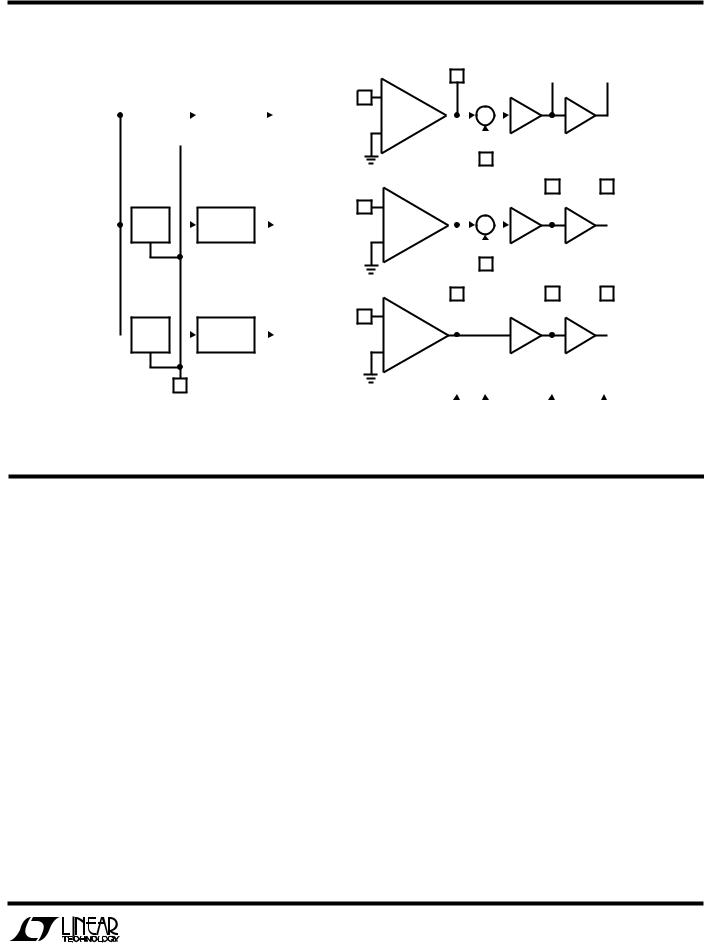
LTC1061
BLOCK DIAGRAW
|
|
|
|
|
|
|
|
|
|
|
INVA |
CLK |
|
|
|
LEVEL |
|
|
|
CLOCK |
(4) |
||
|
|
|
|
|
|
TO FILTER A |
|||||
(8) |
|
|
|
SHIFT |
|
|
|
GENERATOR |
|
||
|
|
|
|
|
|
|
|||||
|
|
|
|
|
|
|
|
|
|
|
|
|
|
|
|
|
|
|
|
|
|
|
|
INVB (17)
LEVEL |
CLOCK |
|
TO FILTER B |
SHIFT |
GENERATOR |
|
|
|
|
INVC (11)
LEVEL |
CLOCK |
|
TO FILTER C |
SHIFT |
GENERATOR |
|
|
|
|
NA |
|
BPA |
|
LPA |
|
|
|||
(3) |
|
(2) |
|
(1) |
|
|
– |
|
|
|
|
|
|
|
|
|
|
|
|||||
|
|
+ |
|
S |
|
+ ò |
+ ò |
|
|
|||||||
+ |
|
|
|
|
|
|
|
|||||||||
|
|
|
|
|
|
– |
|
S1A |
|
|
|
|
|
|
||
|
|
|
|
|
|
|
|
|
|
|
|
|
|
|
||
|
|
|
|
|
|
NB |
(5) |
|
|
|
BPB |
LPB |
||||
|
|
|
|
|
|
|
|
|
|
|
||||||
|
|
|
|
|
|
|
|
|
|
|||||||
|
|
|
|
|
|
(18) |
|
|
|
|
|
(19) |
|
(20) |
||
– |
+ |
|
|
|
|
|
|
|||||||||
|
|
|
|
|
|
|
|
|
|
|
||||||
|
|
|
|
S |
|
+ ò |
|
|
+ ò |
|
|
|||||
+ |
|
|
|
|
|
|
|
|
|
|
||||||
|
|
|
|
|
|
– |
|
S1B |
|
|
|
|
|
|
||
|
|
|
|
|
|
|
|
|
|
|
|
|
|
|
||
|
|
|
|
|
|
|
|
|
(16) |
|
|
|
|
|
|
|
|
|
|
|
|
|
HPC |
|
|
|
|
|
BPC |
LPC |
|||
– |
|
|
(12) |
|
|
|
|
|
(13) |
|
(14) |
|||||
|
|
|
|
|
|
|
||||||||||
|
|
|
|
|
|
|
|
|
|
|
|
|||||
+ |
|
|
|
|
|
|
|
|
+ ò |
|
|
+ ò |
|
|
||
|
|
|
|
|
|
|
|
|
|
|
||||||
|
|
|
|
|
|
|
|
|
|
|
|
|
|
|
|
|
LEVEL SHIFT |
50/100/ |
|
|
|
|
|
|
|
|
|
|
|
V+ |
|
|
V – |
|
|
|
|
|
|
|
|
|
|
|
|
|
||||
(9) |
|
|
|
|
|
|
|
|
AGND |
|
|
|
|
|||
|
HOLD |
|
|
|
|
|
|
|
|
(6) |
|
|
(10) |
|
|
(15) |
|
(7) |
|
|
|
|
|
|
|
|
|
|
|||||
|
|
|
|
|
|
|
|
|
|
|
|
|
|
1061 BD |
||
|
|
|
|
|
|
|
|
|
|
|
|
|
|
|
||
|
|
|
|
|
|
|
|
|
|
|
|
|
|
|
||
|
|
|
|
|
|
|
|
|
|
|
|
|
|
|
||
PIU DESCRIPTIOU AUD APPLICATIOU HIUTS
Power Supplies (Pins 10, 15)
They should be bypassed with 0.1mF disc ceramic. Low noise, nonswitching, power supplies are recommended. The device operates with a single 5V supply, Figure 1, and with dual supplies. The absolute maximum operating power supply voltage is ±9V.
Clock and Level shift (Pins 8, 9)
When the LTC1061 operates with symmetrical dual supplies the level shift Pin 9 should be tied to analog ground. For single 5V supply operation, the level shift pin should be tied to Pin 15 which will be the system ground. The typical logic threshold levels of the clock pin are as follows: 1.65V above the level shift pin for ±5V supply operation, 1.75V for ±7.5V and above, and 1.4V for single 5V supply operation. The logic threshold levels vary ±100mV over the full military temperature range. The recommended duty cycle of the input clock is 50% although for clock
frequencies below 500kHz the clock “on” time can be as low as 300ns. The maximum clock frequency for ±5V supplies and above is 2.4MHz.
S1A, S1B (Pins 5, 16)
These are voltage input pins. If used, they should be driven with a source impedance below 5kW. when they are not used, they should be tied to the analog ground Pin 6.
AGND (Pin 6)
When the LTC1061 operates with dual supplies, Pin 6 should be tied to system ground. When the LTC1061 operates with a single positive supply, the analog ground pin should be tied to 1/2 supply, Figure 1. The positive input of all the internal op amps, as well as the common reference of all the internal switches, are internally tied to the analog ground pin. Because of this, a “clean” ground is recommended.
5
 Loading...