


Linear Technology LT1012S8, LT1012MH, LT1012IN8, LT1012DN8, LT1012DH Datasheet
...
FEATURES
■ OP-07 Type Performance:
at 1/8th of OP-07’s Supply Current
at 1/20th of OP-07’s Bias and Offset Currents
■Guaranteed Offset Voltage: 25 V Max
■Guaranteed Bias Current: 100pA Max
■Guaranteed Drift: 0.6 V/°C Max
■Low Noise, 0.1Hz to 10Hz: 0.5 VP-P
■Guaranteed Low Supply Current: 500 A Max
■Guaranteed CMRR: 114dB Min
■Guaranteed PSRR: 114dB Min
■Guaranteed Operation at ±1.2V Supplies
APPLICATIOUS
■Replaces OP-07 While Saving Power
■Precision Instrumentation
■Charge Integrators
■Wide Dynamic Range Logarithmic Amplifiers
■Light Meters
■Low Frequency Active Filters
■Thermocouple Amplifiers
LT1012A/LT1012
Picoamp Input Current,
Microvolt Offset,
Low Noise Op Amp
DESCRIPTIOU
The LT®1012 is an internally compensated universal precision operational amplifier which can be used in practically all precision applications. The LT1012 combines picoampere bias currents (which are maintained over the full –55°C to 125°C temperature range), microvolt offset voltage (and low drift with time and temperature), low voltage and current noise, and low power dissipation. The LT1012 achieves precision operation on two Ni-Cad batteries with 1mW of power dissipation. Extremely high common mode and power supply rejection ratios, practically unmeasurable warm-up drift, and the ability to deliver 5mA load current with a voltage gain of one million round out the LT1012’s superb precision specifications.
The all around excellence of the LT1012 eliminates the necessity of the time consuming error analysis procedure of precision system design in many applications; the LT1012 can be stocked as the universal internally compensated precision op amp.
, LTC and LT are registered trademarks of Linear Technology Corporation.
Protected by U. S. patents 4,575,685 and 4,775,884
TYPICAL APPLICATIOU
± 250V Common Mode Range Instrumentation Amplifier (AV = 1)
R1 |
R5 |
1M |
975k |
|
–IN |
3 |
4 |
|
|
|
|
1 |
|
|
|
R2 |
|
|
6V TO 18V |
R6 |
50k |
OPTIONAL |
|
|
|
20k |
|
|
|
|
25k |
|
CMRR |
|
|
|
|
2 |
– |
7 |
|
|
TRIM |
|
|
|
|
|
2 |
|
|||
|
|
|
|
|
6 |
|
|||
|
|
R3 |
|
|
|
LT1012 |
OUT |
|
|
|
|
|
|
|
|
|
|||
|
|
1M |
|
3 |
|
|
|
||
COMMON |
|
|
+ |
|
|
|
|
||
+IN |
7 |
6 |
4 |
|
|
|
|||
MODE |
|
|
|
|
|
R1 TO R6: VISHAY 444 |
|||
INPUT |
|
|
|
R4 |
|
|
ACCUTRACT THIN FILM |
||
± 250V |
|
|
|
19.608k |
SIP NETWORK |
|
|||
|
|
|
5 |
|
–6V TO –18V |
X : VISHAY 444 PIN NUMBERS |
|||
|
|
|
|
|
|
||||
|
|
|
|
|
|
VISHAY INTERTECHNOLOGY, INC |
|||
|
|
|
|
|
|
|
|||
|
|
|
|
|
|
|
63 LINCOLN HIGHWAY |
||
|
|
|
|
|
|
|
MALVERN, PA 19355 |
||
COMMON MODE REJECTION RATIO = 74dB (RESISTOR LIMITED) |
|
WITH OPTIONAL TRIM = 130dB |
|
OUTPUT OFFSET (TRIMMABLE TO ZERO) = 500 V |
|
OUTPUT OFFSET DRIFT = 10 V/°C |
|
INPUT RESISTANCE = 1M |
LT1012A • TA01 |
Typical Distribution of Input
Offset Voltage
|
200 |
|
|
|
|
|
|
|
|
|
|
|
|
|
|
|
|
|
|
|
|
|
|
|
|
|
|
|
|
|
|
|
|
|
|
|
1140 UNITS |
|
|
|
|
|
|
|
|
VS = ±15V |
|
||||||||||||||||||
|
|
|
|
FROM THREE |
|
|
|
|
|
|
|
|
|
TA = 25°C |
|
|||||||||||||||||
|
|
|
|
|
|
|
|
|
||||||||||||||||||||||||
UNITS |
160 |
|
|
RUNS |
|
|
|
|
|
|
|
|
|
|
|
|
|
|
|
VCM = 0V |
|
|||||||||||
|
|
|
|
|
|
|
|
|
|
|
|
|
|
|
||||||||||||||||||
120 |
|
|
|
|
|
|
|
|
|
|
|
|
|
|
|
|
|
|
|
|
|
|
|
|
|
|
|
|
|
|
|
|
|
|
|
|
|
|
|
|
|
|
|
|
|
|
|
|
|
|
|
|
|
|
|
|
|
|
|
|
|
|
|
||
|
|
|
|
|
|
|
|
|
|
|
|
|
|
|
|
|
|
|
|
|
|
|
|
|
|
|
|
|
|
|
||
|
|
|
|
|
|
|
|
|
|
|
|
|
|
|
|
|
|
|
|
|
|
|
|
|
|
|
|
|
|
|
||
OF |
|
|
|
|
|
|
|
|
|
|
|
|
|
|
|
|
|
|
|
|
|
|
|
|
|
|
|
|
|
|
|
|
NUMBER |
80 |
|
|
|
|
|
|
|
|
|
|
|
|
|
|
|
|
|
|
|
|
|
|
|
|
|
|
|
|
|
|
|
|
|
|
|
|
|
|
|
|
|
|
|
|
|
|
|
|
|
|
|
|
|
|
|
|
|
|
|
|
|
|
||
|
|
|
|
|
|
|
|
|
|
|
|
|
|
|
|
|
|
|
|
|
|
|
|
|
|
|
|
|
|
|
|
|
|
40 |
|
|
|
|
|
|
|
|
|
|
|
|
|
|
|
|
|
|
|
|
|
|
|
|
|
|
|
|
|
|
|
|
|
|
|
|
|
|
|
|
|
|
|
|
|
|
|
|
|
|
|
|
|
|
|
|
|
|
|
|
|
|
|
|
|
|
|
|
|
|
|
|
|
|
|
|
|
|
|
|
|
|
|
|
|
|
|
|
|
|
|
|
|
|
|
|
|
|
|
|
|
|
|
|
|
|
|
|
|
|
|
|
|
|
|
|
|
|
|
|
|
|
|
|
|
|
|
|
|
|
|
|
|
|
|
|
|
|
|
|
|
|
|
|
|
|
|
|
|
|
|
|
|
|
|
|
|
|
|
|
|
|
|
|
0 |
|
|
|
|
|
|
|
|
|
|
|
|
|
|
|
|
|
|
|
|
|
|
|
|
|
|
|
|
|
|
|
|
|
|
|
|
|
|
|
|
|
|
|
|
|
|
|
|
|
|
|
|
|
|
|
|
|
|
|
|
|
|
|
|
|
|
|
|
|
|
|
|
|
|
|
|
|
|
|
|
|
|
|
|
|
|
|
|
|
|
|
|
|
|
|
|
|
|
|
|
|
|
|
|
|
|
|
|
|
|
|
|
|
|
|
|
|
|
|
|
|
|
|
|
|
|
|
|
|
|
|
|
|
|
|
|
|
|
|
|
|
|
|
|
|
|
|
|
|
|
|
|
|
|
|
|
|
|
|
|
|
|
|
|
|
|
|
–40 |
–20 |
0 |
|
|
20 |
40 |
|
|
||||||||||||||||||||
|
|
|
|
|
|
|
|
|
||||||||||||||||||||||||
INPUT OFFSET VOLTAGE ( V)
LT1012A • TA02
sn1012 1012afbs
1
LT1012A/LT1012
ABSOLUTE
WAXIWUW
RATIUGS
(Note 1)
Supply Voltage ...................................................... |
± 20V |
Operating Temperature Range |
|
|
......................Differential Input Current (Note 1) |
± 10mA |
|
LT1012AM/LT1012M (OBSOLETE).... |
– 55°C to 125°C |
.........................................................Input Voltage |
± 20V |
|
LT1012I/LT1012AI ............................. |
– 40°C to 85°C |
Output Short Circuit Duration .......................... |
Indefinite |
|
LT1012AC/LT1012C |
0°C to 70°C |
|
|
|
LT1012D/LT1012S8 ................................ |
|
|
|
Storage Temperature Range ................. |
– 65°C to 150°C |
|
|
|
Lead Temperature (Soldering, 10 sec).................. |
300°C |
|
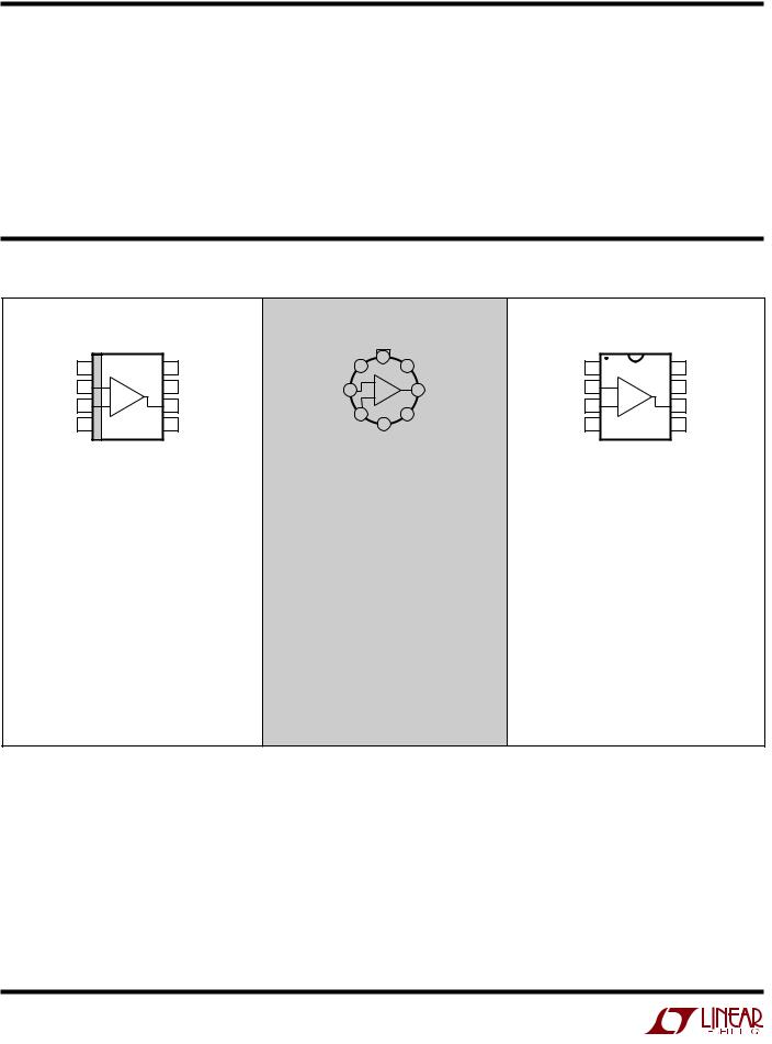
PACKAGE/ORDER IUFORWATIOU |
|
|
|
|
|
|
|
|
||||||
|
|
|
|
|
|
|
TOP VIEW |
|
|
|
|
|
|
|
|
|
TOP VIEW |
|
|
|
|
|
VOS |
|
|
|
TOP VIEW |
|
|
|
|
|
|
VOS |
|
|
TRIM |
|
|
|
|
|
||
VOS |
|
|
|
VOS |
|
|
8 |
V+ |
VOS |
|
|
|
VOS |
|
1 |
|
8 |
TRIM |
1 |
1 |
|
8 |
|||||||
TRIM |
|
TRIM |
|
|
7 |
|
TRIM |
|
TRIM |
|||||
–IN |
2 |
– |
7 |
V+ |
–IN |
2 |
|
– |
6 OUT |
–IN |
2 |
– |
7 |
V+ |
|
+ |
|||||||||||||
+IN |
3 |
+ |
6 |
OUT |
|
|
|
|
+IN |
3 |
+ |
6 |
OUT |
|
+IN |
|
3 |
5 |
OVER |
||||||||||
V– |
4 |
|
5 |
OVER |
|
V – |
4 |
|
5 |
OVER |
||||
|
|
|
4 |
|
||||||||||
|
|
|
|
COMP |
|
|
V |
– (CASE) |
COMP |
|
|
|
|
COMP |
|
|
|
|
|
|
|
|
|
|
|
|
|
||
S8 PACKAGE |
H PACKAGE |
N8 PACKAGE |
|
8-LEAD PLASTIC SO |
8-LEAD TO-5 METAL CAN |
8-LEAD PDIP |
|
TJMAX = 100°C, θJA = 170°C/W |
TJMAX = 150°C, θJA = 150°C/W, θJC = 45°C/W |
TJMAX = 100°C, θJA = 130°C/W |
|
|
|
|
|
ORDER PART NUMBER |
ORDER PART NUMBER |
ORDER PART NUMBER |
|
LT1012S8 |
LT1012AMH |
LT1012ACN8 |
|
LT1012IS8 |
LT1012MH |
LT1012AIN8 |
|
LT1012ACS8 |
LT1012ACH |
LT1012CN8 |
|
LT1012AIS8 |
LT1012CH |
LT1012DN8 |
|
|
LT1012DH |
LT1012IN8 |
|
S8 PART MARKING |
|||
|
|
||
|
|
|
|
1012 |
|
|
|
1012I |
OBSOLETE PACKAGE |
|
|
1012A |
|
||
1012AI |
Consider the S8 or N8 Packages for Alternate Source |
|
Consult LTC Marketing for parts specified with wider operating temperature ranges.
sn1012 1012afbs
2

LT1012A/LT1012
ELECTRICAL CHARACTERISTICS |
VS = ± 15V, VCM = OV, TA = 25°C, unless otherwise noted. |
|
|
|
|
|
|||||||||
|
|
|
|
|
|
|
|
|
|
|
|
|
|||
|
|
|
LT1O12AM/AC/AI |
LT1O12M/I |
|
|
LT1O12C |
|
|
|
|
|
|||
SYMBOL |
PARAMETER |
CONDITIONS |
MIN |
TYP |
MAX |
MIN |
TYP |
MAX |
MIN |
TYP |
MAX |
UNITS |
|||
|
|
|
|
|
|
|
|
|
|
|
|
|
|
|
|
VOS |
Input Offset Voltage |
|
|
8 |
25 |
|
8 |
35 |
|
10 |
50 |
µV |
|||
|
|
(Note 3) |
|
20 |
90 |
|
20 |
90 |
|
25 |
120 |
µV |
|||
|
|
|
|
|
|
|
|
|
|
|
|
|
|
|
|
|
Long Term lnput Offset |
|
|
0.3 |
|
|
0.3 |
|
|
0.3 |
|
µV/month |
|||
|
Voltage Stability |
|
|
|
|
|
|
|
|
|
|
|
|
|
|
|
|
|
|
|
|
|
|
|
|
|
|
|
|
|
|
IOS |
Input Offset Current |
|
|
15 |
100 |
|
15 |
100 |
|
20 |
150 |
pA |
|||
|
|
(Note 3) |
|
25 |
150 |
|
25 |
150 |
|
30 |
200 |
pA |
|||
|
|
|
|
|
|
|
|
|
|
|
|
|
|
|
|
IB |
Input Bias Current |
|
|
±25 |
±100 |
|
±25 |
±100 |
|
±30 |
±150 |
pA |
|||
|
|
(Note 3) |
|
±35 |
±150 |
|
±35 |
±150 |
|
±40 |
±200 |
pA |
|||
|
|
|
|
|
|
|
|
|
|
|
|
|
|
|
|
en |
Input Noise Voltage |
0.1Hz to 10Hz |
|
0.5 |
|
|
0.5 |
|
|
0.5 |
|
µVP-P |
|||
en |
Input Noise Voltage Density |
fO = 10Hz (Note 4) |
|
17 |
30 |
|
17 |
30 |
|
17 |
30 |
nV√ |
|
|
|
|
|
|
|
Hz |
|||||||||||
|
|
fO = 1000Hz (Note 5) |
|
14 |
22 |
|
14 |
22 |
|
14 |
22 |
nV√Hz |
|||
in |
Input Noise Current Density |
fO = 10Hz |
|
20 |
|
|
20 |
|
|
20 |
|
fA/√ |
|
||
|
|
|
|
|
|
Hz |
|||||||||
AVOL |
Large Signal Voltage Gain |
VOUT = ±12V, RL ≥ 10kΩ |
300 |
2000 |
|
300 |
2000 |
|
200 |
2000 |
|
V/mV |
|||
|
|
VOUT = ±10V, RL ≥ 2kΩ |
300 |
1000 |
|
200 |
1000 |
|
200 |
1000 |
|
V/mV |
|||
CMRR |
Common Mode Rejection |
VCM = ±13.5V |
114 |
132 |
|
114 |
132 |
|
110 |
132 |
|
dB |
|||
|
Ratio |
|
|
|
|
|
|
|
|
|
|
|
|
|
|
|
|
|
|
|
|
|
|
|
|
|
|
|
|
|
|
PSRR |
Power SuppIy Rejection Ratio |
VS = ±1.2V to ±20V |
114 |
132 |
|
114 |
132 |
|
110 |
132 |
|
dB |
|||
|
Input Voltage Range |
|
±13.5 |
±14 |
|
±13.5 |
±14 |
|
±13.5 |
±14 |
|
|
|
V |
|
|
|
|
|
|
|
|
|
|
|
|
|
|
|
|
|
VOUT |
Output Voltage Swing |
RL = 10kΩ |
±13 |
±14 |
|
±13 |
±14 |
|
±13 |
±14 |
|
|
|
V |
|
|
Slew Rate |
|
0.1 |
0.2 |
|
0.1 |
0.2 |
|
0.1 |
0.2 |
|
V/µs |
|||
|
|
|
|
|
|
|
|
|
|
|
|
|
|
|
|
IS |
Supply Current |
|
|
370 |
500 |
|
380 |
|
|
380 |
|
µA |
|||
|
|
(Note 3) |
|
380 |
600 |
|
380 |
600 |
|
380 |
600 |
µA |
|||
|
|
|
|
|
|
|
|
|
|
|
|
|
|
|
|
sn1012 1012afbs
3

LT1012A/LT1012
ELECTRICAL CHARACTERISTICS |
VS = ± 15V, VCM = 0V, TA = 25°C, unless otherwise noted. |
|
|
|
|
|
||||||||
|
|
|
|
|
|
|
|
|
|
|
|
|
|
|
|
|
|
|
|
LT1012D |
|
|
LT1012S8 |
|
|
|
|
|
|
SYMBOL |
PARAMETER |
CONDITIONS |
|
MIN |
TYP |
MAX |
MIN |
TYP |
MAX |
UNITS |
||||
|
|
|
|
|
|
|
|
|
|
|
|
|
|
|
VOS |
Input Offset Voltage |
|
|
|
12 |
60 |
|
15 |
120 |
|
|
µV |
||
|
|
(Note 3) |
|
|
25 |
|
|
25 |
180 |
|
|
µV |
||
|
|
|
|
|
|
|
|
|
|
|
|
|
|
|
|
Long Term Input Offset |
|
|
|
0.3 |
|
|
0.4 |
|
µV/month |
||||
|
Voltage Stability |
|
|
|
|
|
|
|
|
|
|
|
|
|
|
|
|
|
|
|
|
|
|
|
|
|
|
|
|
lOS |
Input Offset Current |
|
|
|
20 |
150 |
|
50 |
280 |
|
|
pA |
||
|
|
(Note 3) |
|
|
30 |
|
|
60 |
380 |
|
|
pA |
||
|
|
|
|
|
|
|
|
|
|
|
|
|
|
|
IB |
Input Bias Current |
|
|
|
±30 |
±150 |
|
±80 |
±300 |
|
|
pA |
||
|
|
(Note 3) |
|
|
±40 |
|
|
±120 |
±400 |
|
|
pA |
||
|
|
|
|
|
|
|
|
|
|
|
|
|
|
|
en |
Input Noise Voltage |
0.1Hz to 10Hz |
|
|
0.5 |
|
|
0.5 |
|
µVP-P |
||||
en |
Input Noise Voltage Density |
fO = 10Hz (Note 5) |
|
|
17 |
30 |
|
17 |
30 |
nV√ |
|
|
|
|
|
|
|
Hz |
|||||||||||
|
|
fO = 1000Hz (Note 5) |
|
|
14 |
22 |
|
14 |
22 |
nV√Hz |
||||
in |
lnput Noise Current Density |
fO = 10Hz |
|
|
20 |
|
|
20 |
|
fA/√ |
|
|
||
|
|
|
|
|
Hz |
|||||||||
AVOL |
Large-Signal Voltage Gain |
VOUT = ±12V,RL ≥ 10kΩ |
|
200 |
2000 |
|
200 |
2000 |
|
V/mV |
||||
|
|
VOUT = ±10V,RL ≥ 2kΩ |
|
200 |
1000 |
|
120 |
1000 |
|
V/mV |
||||
CMRR |
Common Mode Rejection Ratio |
VCM = ±13.5V |
|
110 |
132 |
|
110 |
132 |
|
|
|
dB |
||
PSRR |
Power Supply Rejection Ratio |
VS = ±1.2V to ±20V |
|
110 |
132 |
|
110 |
132 |
|
|
|
dB |
||
|
Input Voltage Range |
|
|
±13.5 |
±14.0 |
|
±13.5 |
±14.0 |
|
|
|
V |
||
|
|
|
|
|
|
|
|
|
|
|
|
|
|
|
VOUT |
Output Voltage Swing |
RL = 10kΩ |
|
±13 |
±14 |
|
±13 |
±14 |
|
|
|
V |
||
|
Slew Rate |
|
|
0.1 |
0.2 |
|
0.1 |
0.2 |
|
V/µs |
||||
|
|
|
|
|
|
|
|
|
|
|
|
|
|
|
IS |
Supply Current |
(Note 3) |
|
|
380 |
600 |
|
380 |
600 |
|
|
µA |
||
sn1012 1012afbs
4

LT1012A/LT1012
ELECTRICAL CHARACTERISTICS The ● denotes the specifications which apply over the full operating temperature range of –55°C ≤ TA ≤ 125°C for LT1012AM and LT1012M, and –40°C ≤ TA≤ 85°C for LT1012AI and LT1012I.
VS = ± 15V, VCM = 0V, unless otherwise noted.
|
|
|
|
|
LT1012AM/AI |
|
|
LT1012M/I |
|
|
SYMBOL |
PARAMETER |
CONDITIONS |
|
MIN |
TYP |
MAX |
MIN |
TYP |
MAX |
UNITS |
|
|
|
|
|
|
|
|
|
|
|
VOS |
Input Offset Voltage |
|
● |
|
30 |
60 |
|
30 |
180 |
µV |
|
|
(Note 3) |
● |
|
40 |
180 |
|
40 |
250 |
µV |
|
|
|
|
|
|
|
|
|
|
|
|
Average Temperature Coefficient of |
|
● |
|
0.2 |
0.6 |
|
0.2 |
1.5 |
µV/°C |
|
Input Offset Voltage |
|
|
|
|
|
|
|
|
|
|
|
|
|
|
|
|
|
|
|
|
IOS |
Input Offset Current |
(Note 3) |
● |
|
30 |
250 |
|
30 |
250 |
pA |
|
|
● |
|
70 |
350 |
|
70 |
350 |
pA |
|
|
|
|
|
|
|
|
|
|
|
|
|
Average Temperature Coefficient of |
|
● |
|
0.3 |
2.5 |
|
0.3 |
2.5 |
pA/°C |
|
Input Offset Current |
|
|
|
|
|
|
|
|
|
|
|
|
|
|
|
|
|
|
|
|
IB |
Input Bias Current |
|
● |
|
±80 |
±600 |
|
±80 |
±600 |
pA |
|
|
(Note 3) |
● |
|
±150 |
±800 |
|
±150 |
±800 |
pA |
|
|
|
|
|
|
|
|
|
|
|
|
Average Temperature Coefficient of |
|
● |
|
0.6 |
6.0 |
|
0.6 |
6.0 |
pA/°C |
|
Input Bias Current |
|
|
|
|
|
|
|
|
|
|
|
|
|
|
|
|
|
|
|
|
AVOL |
Large-Signal Voltage Gain |
VOUT = ±12V, RL ≥ 10kΩ |
● |
200 |
1000 |
|
150 |
1000 |
|
V/mV |
|
|
VOUT = ±10V, RL ≥ 2kΩ |
● |
200 |
600 |
|
100 |
600 |
|
V/mV |
CMRR |
Common Mode Rejection Ratio |
VCM = ±13.5V |
● |
110 |
128 |
|
108 |
128 |
|
dB |
PSRR |
Power Supply Rejection Ratio |
VS = ±1.5V to ±20V |
● |
110 |
126 |
|
108 |
126 |
|
dB |
|
Input Voltage Range |
|
● |
±13.5 |
|
|
±13.5 |
|
|
V |
|
|
|
|
|
|
|
|
|
|
|
VOUT |
Output Voltage Swing |
RL = 10kΩ |
● |
±13 |
±14 |
|
±13 |
±14 |
|
V |
IS |
Supply Current |
|
● |
|
400 |
650 |
|
400 |
800 |
µA |
sn1012 1012afbs
5

LT1012A/LT1012
ELECTRICAL CHARACTERISTICS The ● denotes the specifications which apply over the full operating temperature range of 0°C ≤ TA ≤ 70°C. VS = ± 15V, VCM = 0V, unless otherwise noted.
|
|
|
|
|
LT1012AC |
|
|
LT1012C |
|
|
SYMBOL |
PARAMETER |
CONDITIONS |
|
MIN |
TYP |
MAX |
MIN |
TYP |
MAX |
UNITS |
|
|
|
|
|
|
|
|
|
|
|
VOS |
Input Offset Voltage |
|
● |
|
20 |
60 |
|
20 |
100 |
µV |
|
|
(Note 3) |
● |
|
30 |
160 |
|
30 |
200 |
µV |
|
|
|
|
|
|
|
|
|
|
|
|
Average Temperature Coefficient of |
|
● |
|
0.2 |
0.6 |
|
0.2 |
1.0 |
µV/°C |
|
Input Offset Voltage |
|
|
|
|
|
|
|
|
|
|
|
|
|
|
|
|
|
|
|
|
IOS |
Input Offset Current |
|
● |
|
25 |
230 |
|
35 |
230 |
pA |
|
|
(Note 3) |
● |
|
40 |
300 |
|
45 |
300 |
pA |
|
|
|
|
|
|
|
|
|
|
|
|
Average Temperature Coefficient of |
|
● |
|
0.3 |
2.5 |
|
0.3 |
2.5 |
pA/°C |
|
Input Offset Current |
|
|
|
|
|
|
|
|
|
|
|
|
|
|
|
|
|
|
|
|
IB |
Input Bias Current |
|
● |
|
±35 |
±230 |
|
±35 |
±230 |
pA |
|
|
(Note 3) |
● |
|
±50 |
±300 |
|
±50 |
±300 |
pA |
|
|
|
|
|
|
|
|
|
|
|
|
Average Temperature Coefficient of |
|
● |
|
0.3 |
2.5 |
|
0.3 |
2.5 |
pA/°C |
|
Input Bias Current |
|
|
|
|
|
|
|
|
|
|
|
|
|
|
|
|
|
|
|
|
AVOL |
Large-Signal Voltage Gain |
VOUT = ±12V, RL ≥ 10kΩ |
● |
200 |
1500 |
|
150 |
1500 |
|
V/mV |
|
|
VOUT = ±10V, RL ≥ 2kΩ |
● |
200 |
1000 |
|
150 |
800 |
|
V/mV |
CMRR |
Common Mode Rejection Ratio |
VCM = 13.5V |
● |
110 |
130 |
|
108 |
130 |
|
dB |
PSRR |
Power Supply Rejection Ratio |
VS = ±1.3V to ±20V |
● |
110 |
128 |
|
108 |
128 |
|
dB |
|
Input Voltage Range |
|
● |
±13.5 |
|
|
±13.5 |
|
|
V |
|
|
|
|
|
|
|
|
|
|
|
VOUT |
Output Voltage Swing |
RL = 10kΩ |
● |
±13 |
±14 |
|
±13 |
±14 |
|
V |
IS |
Supply Current |
|
● |
|
400 |
600 |
|
400 |
800 |
µA |
sn1012 1012afbs
6
 Loading...