


Linear Technology LT1014MJ, LT1014IS, LT1013ACH, LT1013, LT1013MH Datasheet
...FEATURES
■ |
Single Supply Operation |
|
|
Input Voltage Range Extends to Ground |
|
|
Output Swings to Ground while Sinking Current |
|
■ |
Pin Compatible to 1458 and 324 with Precision Specs |
|
■ |
Guaranteed Offset Voltage |
150mV Max. |
■ |
Guaranteed Low Drift |
2mV/°C Max. |
■ |
Guaranteed Offset Current |
0.8nA Max. |
■ |
Guaranteed High Gain |
|
|
5mA Load Current |
1.5 Million Min. |
|
17mA Load Current |
0.8 Million Min. |
■ |
Guaranteed Low Supply Current |
500mA Max. |
■ |
Low Voltage Noise, 0.1Hz to 10Hz |
0.55mVp-p |
■ |
Low Current Noise—Better than 0P-07, 0.07pA/ÖHz |
|
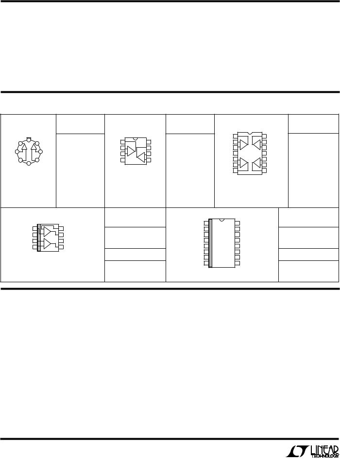
LT1013/LT1014
Quad Precision Op Amp (LT1014)
Dual Precision Op Amp (LT1013)
DESCRIPTIOU
TheLT ®1014isthefirstprecisionquadoperationalamplifier which directly upgrades designs in the industry standard 14-pin DIP LM324/LM348/OP-11/4156 pin configuration. It is no longer necessary to compromise specifications, while saving board space and cost, as compared to single operational amplifiers.
The LT1014’s low offset voltage of 50mV, drift of 0.3mV/°C, offset current of 0.15nA, gain of 8 million, common-mode rejection of 117dB and power supply rejection of 120dB qualify it as four truly precision operational amplifiers. Particularly important is the low offset voltage, since no offset null terminals are provided in the quad configuration. Although supply current is only 350mA per amplifier, a new output stage design sources and sinks in excess of 20mA of load current, while retaining high voltage gain.
APPLICATIOUS
■Battery-Powered Precision Instrumentation Strain Gauge Signal Conditioners Thermocouple Amplifiers Instrumentation Amplifiers
■4mA–20mA Current Loop Transmitters
■Multiple Limit Threshold Detection
■Active Filters
■Multiple Gain Blocks
, LTC and LT are registered trademarks of Linear Technology Corporation.
Similarly, the LT1013 is the first precision dual op amp in the 8-pin industry standard configuration, upgrading the performance of such popular devices as the MC1458/ 1558, LM158 and OP-221. The LT1013’s specifications are similar to (even somewhat better than) the LT1014’s.
Both the LT1013 and LT1014 can be operated off a single 5V power supply: input common-mode range includes ground; the output can also swing to within a few millivolts of ground. Crossover distortion, so apparent on previous single-supply designs, is eliminated. A full set of specifications is provided with ±15V and single 5V supplies.
3 Channel Thermocouple Thermometer |
LT1014 Distribution of Offset Voltage |
|
|
|
|
4k |
|
|
1M |
|
|
|
|
3k |
299k |
|
|
|
|
|
|
|
|
|
+5V |
|
|
|
|
|
+5V |
|
|
|
|
LT1004 |
|
YSI 44007 |
2 |
– |
4 |
|
|
|
|
|
|
1.2V |
1684Ω |
5kΩ |
|
|
1 |
OUTPUT A |
|
|
|
+ |
12 |
|
AT 25°C |
3 |
LT1014 |
UNITS |
|||
|
|
|
|
10mV/°C |
||||||
|
|
|
|
|
|
|
|
|||
|
|
|
|
|
|
+ |
|
|
|
|
14 |
|
|
|
|
|
11 |
|
|
OF |
|
LT1014 |
|
|
|
|
|
|
|
|||
|
13 |
260Ω |
1.8k |
|
|
1M |
|
|
NUMBER |
|
|
– |
|
|
|
|
|||||
|
|
|
|
|
|
|
||||
|
|
|
|
|
|
|
|
|
||
|
|
|
|
|
|
|
|
|
|
|
|
|
|
|
4k |
6 |
– |
|
|
|
|
|
|
|
|
|
|
|
|
|
||
USE TYPE K THERMOCOUPLES. ALL RESISTORS = 1% FILM. |
LT1014 |
7 |
OUTPUT B |
||
COLD JUNCTION COMPENSATION ACCURATE |
|
10mV/°C |
|||
5 |
|
||||
TO ±1°C FROM 0°C |
|
60°C. |
|
|
|
|
+ |
|
|
||
USE 4TH AMPLIFIER FOR OUTPUT C. |
|
|
|
||
700
VS = ±15V
600TA = 25°C 425 LT1014s
(1700 OP AMPS)
500TESTED FROM THREE RUNS
400 J PACKAGE
300 |
|
|
|
|
|
|
200 |
|
|
|
|
|
|
100 |
|
|
|
|
|
|
0 |
|
|
0 |
100 |
200 |
300 |
–300 |
–200 |
–100 |
INPUT OFFSET VOLTAGE ( V)
1
LT1013/LT1014 |
|
|
|
|
|
|
|
|
|
|
|
|
|
|
|
|
|||||||
ABSOLUTE WAXIWUW RATINGSU |
|
|
|
|
|
|
|
|
|
|
|
||||||||||||
Supply Voltage ...................................................... ±22V |
Lead Temperature (Soldering, 10 sec.)................. 300°C |
||||||||||||||||||||||
Differential Input Voltage ....................................... ±30V |
Operating Temperature Range |
|
|
|
|||||||||||||||||||
Input Voltage ............... Equal to Positive Supply Voltage |
LT1013AM/LT1013M/ |
|
|
|
|
|
|||||||||||||||||
|
|
|
|
|
............5V Below Negative Supply Voltage |
LT1014AM/LT1014M ...................... – 55 °C to 125°C |
|||||||||||||||||
Output Short-Circuit Duration .......................... Indefinite |
LT1013AC/LT1013C/LT1013D |
|
|||||||||||||||||||||
Storage Temperature Range |
|
|
|
|
|
|
LT1014AC/LT1014C/LT1014D ................. 0°C to 70°C |
||||||||||||||||
All Grades ......................................... – 65°C to 150°C |
LT1013I/ LT1014I ............................... – 40°C to 85°C |
||||||||||||||||||||||
PACKAGE/ORDER IUFORWATIOU |
|
|
|
|
|
|
|
|
|
|
|||||||||||||
|
|
|
|
|
|
ORDER PART |
|
|
|
|
|
|
ORDER PART |
|
|
|
|
|
|
|
ORDER PART |
||
|
|
TOP VIEW |
|
|
NUMBER |
|
|
|
|
|
|
NUMBER |
|
|
|
TOP VIEW |
|
|
|
|
NUMBER |
||
|
|
|
|
|
|
|
|
|
|
|
|
|
|
|
|
|
|
||||||
|
|
V+ |
|
|
|
LT1013AMH |
|
|
TOP VIEW |
|
|
|
LT1013AMJ8 |
OUTPUT A |
1 |
|
|
14 |
OUTPUT D |
LT1014AMJ |
|||
OUTPUT A |
1 |
8 |
|
7 |
OUTPUT B |
|
OUTPUT A |
1 |
|
|
8 |
V + |
–IN A |
2 |
– |
– |
13 |
–IN D |
|||||
|
|
|
|
|
|
|
LT1013MH |
|
|
|
|
|
|
LT1013MJ8 |
|
|
A |
D |
|
|
|
LT1014MJ |
|
|
|
A |
|
B |
6 –IN B |
|
–IN A |
2 |
–A |
|
7 |
OUTPUT B |
+IN A |
3 |
+ |
+ |
12 |
+IN D |
|||||
–IN A 2 |
– |
+ |
|
+ – |
|
|
|
|
|
|
V + |
4 |
|
|
11 |
V |
– |
||||||
|
|
|
|
|
LT1013ACH |
+IN A |
3 |
+ |
– |
6 |
–IN B |
LT1013ACJ8 |
|
|
|
LT1014ACJ |
|||||||
+IN A |
3 |
|
|
5 |
+IN B |
|
V – |
4 |
B |
5 |
+IN B |
+IN B |
5 |
+ |
+ |
10 |
+IN C |
||||||
|
|
|
|
+ |
|||||||||||||||||||
|
|
4 |
|
|
|
|
LT1013CH |
|
|
|
|
|
|
LT1013CJ8 |
|
|
6 |
B |
C |
9 |
–IN C |
LT1014CJ |
|
|
|
|
|
|
|
|
|
|
|
|
|
|
–IN B |
– |
– |
||||||||
|
|
V–(CASE) |
|
|
|
|
J PACKAGE |
|
|
|
|||||||||||||
|
|
|
|
|
|
|
|
|
OUTPUT B |
7 |
|
|
8 |
OUTPUT C |
|||||||||
|
H PACKAGE |
|
|
|
|
8-LEAD CERAMIC DIP |
|
LT1013ACN8 |
|
|
LT1014ACN |
||||||||||||
|
|
|
|
|
|
|
|
|
|
|
|
|
|
|
|
|
|||||||
8-LEAD TO-5 METAL CAN |
|
|
|
|
N PACKAGE |
|
|
|
|
J PACKAGE |
|
|
|
||||||||||
|
|
|
|
|
|
|
|
|
8-LEAD PLASTIC DIP |
|
LT1013CN8 |
|
|
|
|
|
LT1014CN |
||||||
|
|
|
|
|
|
|
|
|
|
|
14-LEAD CERAMIC DIP |
|
|
||||||||||
|
|
|
|
|
|
|
|
|
|
|
|
|
|
|
|
|
|||||||
|
|
|
|
|
|
|
|
|
|
|
|
|
|
|
|
N PACKAGE |
|
|
|
||||
|
|
|
|
|
|
|
|
|
|
|
|
|
|
LT1013DN8 |
|
|
|
|
|
LT1014DN |
|||
|
|
|
|
|
|
|
|
|
|
|
|
|
|
|
14-LEAD PLASTIC DIP |
|
|
||||||
|
|
|
|
|
|
|
|
|
|
|
|
|
|
|
|
|
|
|
|
|
|||
|
|
|
|
|
|
|
|
|
|
|
|
|
|
LT1013IN8 |
|
|
|
|
|
|
|
|
LT1014IN |
|
|
|
|
|
|
|
|
ORDER PART |
|
|
TOP VIEW |
|
|
|
|
|
|
ORDER PART |
|||||
|
|
|
|
|
TOP VIEW |
|
|
|
NUMBER |
|
OUTPUT A |
1 |
|
16 |
OUTPUT D |
|
|
|
|
NUMBER |
|||
|
|
|
|
|
|
|
|
|
|
|
|
|
|
|
|||||||||
|
|
+INA |
1 |
|
8 |
–INA |
|
|
–IN A |
2 |
|
15 |
|
|
|
|
|
||||||
|
|
– |
LT1013DS8 |
|
|
–IN D |
|
|
|
|
LT1014DS |
||||||||||||
|
|
V |
– |
2 |
+ |
7 |
OUTA |
|
+IN A |
3 |
|
14 |
+IN D |
|
|
|
|
||||||
|
|
|
|
|
|
|
|
|
|
||||||||||||||
|
|
+INB |
3 |
+ |
6 |
V+ |
LT1013IS8 |
|
|
V+ |
4 |
|
13 |
V– |
|
|
|
|
LT1014IS |
||||
|
|
–INB |
4 |
– |
5 |
OUTB |
|
|
+IN B |
5 |
|
12 |
+IN C |
|
|
|
|
||||||
|
|
|
|
|
|
|
|
|
|
|
|
|
|
||||||||||
|
|
|
|
|
SO PACKAGE |
|
|
PART MARKING |
–IN B |
6 |
|
11 |
–IN C |
|
|
|
|
PART MARKING |
|||||
|
|
|
|
|
|
|
OUTPUT B |
7 |
|
10 |
OUTPUT C |
|
|
|
|
||||||||
|
|
|
|
8-LEAD PLASTIC SOIC |
|
|
|
|
|
||||||||||||||
NOTE: THIS PIN CONFIGURATION DIFFERS FROM |
|
|
1013 |
|
|
|
NC |
8 |
|
9 |
NC |
|
|
|
|
LT1014DS |
|||||||
THE STANDARD 8-PIN DUAL-IN-LINE CONFIGURATION |
|
|
|
|
|
|
|
|
|
|
|
|
|
|
|||||||||
|
|
|
|
|
|
|
|
|
|
|
|
|
|
|
SO PACKAGE |
|
|
|
|
|
|
||
|
|
|
|
|
|
|
|
|
|
1013I |
|
|
|
16-LEAD PLASTIC SOIC |
|
|
|
|
|
LT1014IS |
|||
|
|
|
|
|
|
|
|
|
|
|
|
|
|
|
|
|
|
|
|
|
|||
ELECTRICAL CHARACTERISTICS VS = ±15V, VCM = 0V, TA = 25°C unless otherwise noted
|
|
|
|
LT1013AM/AC |
|
|
LT1013C/D/I/M |
|
|
|
|
|
|
|
SYMBOL |
PARAMETER |
CONDITIONS |
|
LT1014AM/AC |
|
|
LT1014C/D/I/M |
|
UNITS |
|||||
|
|
|
MIN |
TYP |
MAX |
MIN |
TYP |
MAX |
|
|
|
|
|
|
VOS |
Input Offset Voltage |
LT1013 |
— |
40 |
150 |
— |
60 |
300 |
|
mV |
||||
|
|
LT1014 |
— |
50 |
180 |
— |
60 |
300 |
|
mV |
||||
|
|
LT1013D/I, LT1014D/I |
— |
— |
— |
— |
200 |
800 |
|
mV |
||||
|
Long Term Input Offset Voltage |
|
— |
0.4 |
— |
— |
0.5 |
— |
mV/Mo. |
|||||
|
Stability |
|
|
|
|
|
|
|
|
|
|
|
|
|
ISO |
Input Offset Current |
|
— |
0.15 |
0.8 |
— |
0.2 |
1.5 |
nA |
|||||
IB |
Input Bias Current |
|
— |
12 |
20 |
— |
15 |
30 |
|
nA |
||||
en |
Input Noise Voltage |
0.1Hz to 10Hz |
— |
0.55 |
— |
— |
0.55 |
— |
mVp-p |
|||||
en |
Input Noise Voltage Density |
fO = 10Hz |
— |
24 |
— |
— |
24 |
— |
nV/Ö |
|
|
|||
Hz |
||||||||||||||
|
|
fO = 1000Hz |
— |
22 |
— |
— |
22 |
— |
nV/Ö |
Hz |
|
|||
in |
Input Noise Current Density |
fO = 10Hz |
— |
0.07 |
— |
— |
0.07 |
— |
pA/Ö |
|
|
|
||
Hz |
||||||||||||||
2

LT1013/LT1014
ELECTRICAL CHARACTERISTICS
VS = ±15V, VCM = 0V, TA = 25°C unless otherwise noted
|
|
|
|
LT1013AM/AC |
|
|
LT1013C/D/I/M |
|
|
SYMBOL |
PARAMETER |
CONDITIONS |
|
LT1014AM/AC |
|
|
LT1014C/D/I/M |
|
UNITS |
|
|
|
MIN |
TYP |
MAX |
MIN |
TYP |
MAX |
|
|
|
|
|
|
|
|
|
|
|
|
Input Resistance – Differential |
(Note 1) |
100 |
400 |
— |
70 |
300 |
— |
MΩ |
|
Common-Mode |
|
— |
5 |
— |
— |
4 |
— |
GΩ |
|
|
|
|
|
|
|
|
|
|
AVOL |
Large Signal Voltage Gain |
VO = ±10V, RL = 2k |
1.5 |
8.0 |
— |
1.2 |
7.0 |
— |
V/μV |
|
|
VO = ±10V, RL = 600Ω |
0.8 |
2.5 |
— |
0.5 |
2.0 |
— |
V/μV |
|
Input Voltage Range |
|
+13.5 |
+13.8 |
— |
+13.5 |
+13.8 |
— |
V |
|
|
|
– 15.0 |
– 15.3 |
— |
– 15.0 |
– 15.3 |
— |
V |
CMRR |
Common-Mode Rejection Ratio |
VCM = +13.5V, – 15.0V |
100 |
117 |
— |
97 |
114 |
— |
dB |
PSRR |
Power Supply Rejection Ratio |
VS = ±2V to ±18V |
103 |
120 |
— |
100 |
117 |
— |
dB |
|
Channel Separation |
VO = ±10V, RL = 2k |
123 |
140 |
— |
120 |
137 |
— |
dB |
VOUT |
Output Voltage Swing |
RL = 2k |
±13 |
±14 |
— |
±12.5 |
±14 |
— |
V |
|
Slew Rate |
|
0.2 |
0.4 |
— |
0.2 |
0.4 |
— |
V/μs |
IS |
Supply Current |
Per Amplifier |
— |
0.35 |
0.50 |
— |
0.35 |
0.55 |
mA |
Note 1: This parameter is guaranteed by design and is not tested. Typical parameters are defined as the 60% yield of parameter distributions of individual amplifiers; i.e., out of 100 LT1014s (or 100 LT1013s) typically 240 op amps (or 120 ) will be better than the indicated specification.
ELECTRICAL CHARACTERISTICS
V |
+ |
= + 5V, V |
S |
– = 0V, V |
= 1.4V, V |
= 0V, T = 25°C unless otherwise noted |
|
|
|
|
|
||||
|
S |
|
|
OUT |
CM |
|
A |
|
|
|
|
|
|
|
|
|
|
|
|
|
|
|
|
|
|
LT1013AM/AC |
|
|
LT1013C/D/I/M |
|
|
SYMBOL |
PARAMETER |
|
|
CONDITIONS |
|
LT1014AM/AC |
|
|
LT1014C/D/I/M |
|
UNITS |
||||
|
|
|
|
|
|
|
|
|
MIN |
TYP |
MAX |
MIN |
TYP |
MAX |
|
|
|
|
|
|
|
|
|
|
|
|
|
||||
VOS |
|
Input Offset Voltage |
|
LT1013 |
— |
60 |
250 |
— |
90 |
450 |
μV |
||||
|
|
|
|
|
|
|
|
LT1014 |
— |
70 |
280 |
— |
90 |
450 |
μV |
|
|
|
|
|
|
|
|
LT1013D/I, LT1014D/I |
— |
— |
— |
— |
250 |
950 |
μV |
|
|
|
|
|
|
|
|
|
|
|
|
||||
IOS |
|
Input Offset Current |
|
|
— |
0.2 |
1.3 |
— |
0.3 |
2.0 |
nA |
||||
IB |
|
|
Input Bias Current |
|
|
— |
15 |
35 |
— |
18 |
50 |
nA |
|||
AVOL |
|
Large Signal Voltage Gain |
|
VO = 5mV to 4V, RL = 500Ω |
— |
1.0 |
— |
— |
1.0 |
— |
V/μV |
||||
|
|
|
Input Voltage Range |
|
|
+ 3.5 |
+3.8 |
— |
+3.5 |
+ 3.8 |
— |
V |
|||
|
|
|
|
|
|
|
|
|
0 |
– 0.3 |
— |
0 |
– 0.3 |
— |
V |
|
|
|
|
|
|
|
|
|
|
|
|||||
VOUT |
Output Voltage Swing |
|
Output Low, No Load |
— |
15 |
25 |
— |
15 |
25 |
mV |
|||||
|
|
|
|
|
|
|
|
Output Low, 600Ω to Ground |
— |
5 |
10 |
— |
5 |
10 |
mV |
|
|
|
|
|
|
|
|
Output Low, ISINK = 1mA |
— |
220 |
350 |
— |
220 |
350 |
mV |
|
|
|
|
|
|
|
|
Output High, No Load |
4.0 |
4.4 |
— |
4.0 |
4.4 |
— |
V |
|
|
|
|
|
|
|
|
Output High, 600Ω to Ground |
3.4 |
4.0 |
— |
3.4 |
4.0 |
— |
V |
|
|
|
|
|
|
|
|
|
|
|
|
|
|
||
IS |
|
|
Supply Current |
|
|
Per Amplifier |
— |
0.31 |
0.45 |
— |
0.32 |
0.50 |
mA |
||
3

LT1013/LT1014
ELECTRICAL CHARACTERISTICS VS = ±15V, VCM = 0V, – 55°C ≤ TA ≤ 125°C unless otherwise noted
SYMBOL |
PARAMETER |
CONDITIONS |
|
LT1013AM |
|
|
LT1014AM |
LT1013M/LT1014M |
UNITS |
||||
|
MIN |
TYP |
MAX |
MIN |
TYP |
MAX |
MIN |
TYP |
MAX |
||||
|
|
|
|
|
|
|
|
|
|
|
|
|
|
VOS |
Input Offset Voltage |
VS = +5V, 0V; VO = +1.4V |
● |
— |
80 |
300 |
— |
90 |
350 |
— |
110 |
550 |
μV |
|
|
– 55°C ≤ TA ≤ 100°C |
● |
— |
80 |
450 |
— |
90 |
480 |
— |
100 |
750 |
μV |
|
|
VCM = 0.1V, TA = 125°C |
|
— |
120 |
450 |
— |
150 |
480 |
— |
200 |
750 |
μV |
|
|
VCM = 0V, TA = 125°C |
|
— |
250 |
900 |
— |
300 |
960 |
— |
400 |
1500 |
μV |
|
Input Offset Voltage Drift |
(Note 2) |
● |
— |
0.4 |
2.0 |
— |
0.4 |
2.0 |
— |
0.5 |
2.5 |
μV/°C |
IOS |
Input Offset Current |
|
● |
— |
0.3 |
2.5 |
— |
0.3 |
2.8 |
— |
0.4 |
5.0 |
nA |
|
|
VS = +5V, 0V; VO = +1.4V |
● |
— |
0.6 |
6.0 |
— |
0.7 |
7.0 |
— |
0.9 |
10.0 |
nA |
IB |
Input Bias Current |
|
● |
— |
15 |
30 |
— |
15 |
30 |
— |
18 |
45 |
nA |
|
|
VS = +5V, 0V; VO = +1.4V |
● |
— |
20 |
80 |
— |
25 |
90 |
— |
28 |
120 |
nA |
AVOL |
Large Signal Voltage Gain |
VO = ±10V, RL = 2k |
● |
0.5 |
2.0 |
— |
0.4 |
2.0 |
— |
0.25 |
2.0 |
— |
V/μV |
CMRR |
Common-Mode Rejection |
VCM = +13.0V, – 14.9V |
● |
97 |
114 |
— |
96 |
114 |
— |
94 |
113 |
— |
dB |
PSRR |
Power Supply Rejection |
VS = ±2V to ±18V |
● |
100 |
117 |
— |
100 |
117 |
— |
97 |
116 |
— |
dB |
|
Ratio |
|
|
|
|
|
|
|
|
|
|
|
|
VOUT |
Output Voltage Swing |
RL = 2k |
● |
±12 |
±13.8 |
— |
±12 |
±13.8 |
— |
±11.5 |
±13.8 |
— |
V |
|
|
VS = +5V, 0V |
|
|
|
|
|
|
|
|
|
|
|
|
|
RL = 600Ω to Ground |
|
— |
6 |
15 |
— |
6 |
15 |
— |
6 |
18 |
mV |
|
|
Output Low |
● |
||||||||||
|
|
Output High |
● |
3.2 |
3.8 |
— |
3.2 |
3.8 |
— |
3.1 |
3.8 |
— |
V |
IS |
Supply Current |
|
● |
— |
0.38 |
0.60 |
— |
0.38 |
0.60 |
— |
0.38 |
0.7 |
mA |
|
Per Amplifier |
VS = +5V, 0V; VO = +1.4V |
● |
— |
0.34 |
0.55 |
— |
0.34 |
0.55 |
— |
0.34 |
0.65 |
mA |
ELECTRICAL CHARACTERISTICS
VS = ±15V, VCM = 0V, –40°C ≤ TA ≤ 85°C for LT1013I, LT1014I, 0°C ≤ TA ≤ 70°C for LT1013C, LT1013D, LT1014C, LT1014D unless otherwise noted
SYMBOL |
PARAMETER |
CONDITIONS |
|
|
LT1013AC |
LT1014AC |
|
LT1013C/D/I |
UNITS |
|||||
|
|
|
LT1014C/D/I |
|||||||||||
|
|
|
|
|
|
|
|
|||||||
|
|
|
|
|
MIN |
TYP |
MAX |
MIN |
TYP |
MAX |
MIN |
TYP |
MAX |
|
|
|
|
|
|
|
|
|
|
|
|
|
|
|
|
VOS |
Input Offset Voltage |
|
|
● |
— |
55 |
240 |
— |
65 |
270 |
— |
80 |
400 |
μV |
|
|
LT1013D/I, LT1014D/I |
|
● |
— |
— |
— |
— |
— |
— |
— |
230 |
1000 |
μV |
|
|
VS = +5V, 0V; VO = 1.4V |
|
● |
— |
75 |
350 |
— |
85 |
380 |
— |
110 |
570 |
μV |
|
|
LT1013D/I, LT1014D/I |
|
|
|
|
|
|
|
|
|
|
|
μV |
|
|
VS = +5V, 0V; VO = 1.4V |
|
● |
— |
— |
— |
— |
— |
— |
— |
280 |
1200 |
|
|
Average Input Offset |
(Note 2) |
|
● |
— |
0.3 |
2.0 |
— |
0.3 |
2.0 |
— |
0.4 |
2.5 |
μV/°C |
|
Voltage Drift |
LT1013D/I, LT1014D/I |
|
● |
— |
— |
— |
— |
— |
— |
— |
0.7 |
5.0 |
μV/°C |
IOS |
Input Offset Current |
|
|
● |
— |
0.2 |
1.5 |
— |
0.2 |
1.7 |
— |
0.3 |
2.8 |
nA |
|
|
VS = +5V, 0V; VO = 1.4V |
|
● |
— |
0.4 |
3.5 |
— |
0.4 |
4.0 |
— |
0.5 |
6.0 |
nA |
IB |
Input Bias Current |
|
|
● |
— |
13 |
25 |
— |
13 |
25 |
— |
16 |
38 |
nA |
|
|
VS = +5V, 0V; VO = 1.4V |
|
● |
— |
18 |
55 |
— |
20 |
60 |
— |
24 |
90 |
nA |
AVOL |
Large Signal Voltage Gain |
VO = ±10V, RL = 2k |
|
● |
1.0 |
5.0 |
— |
1.0 |
5.0 |
— |
0.7 |
4.0 |
— |
V/μV |
CMRR |
Common-Mode Rejection |
VCM = +13.0V, – 15.0V |
|
● |
98 |
116 |
— |
98 |
116 |
— |
94 |
113 |
— |
dB |
|
Ratio |
|
|
|
|
|
|
|
|
|
|
|
|
|
PSRR |
Power Supply Rejection |
VS = ±2V to ±18V |
|
● |
101 |
119 |
— |
101 |
119 |
— |
97 |
116 |
— |
dB |
|
Ratio |
|
|
|
|
|
|
|
|
|
|
|
|
|
VOUT |
Output Voltage Swing |
RL = 2k |
|
● |
±12.5 |
±13.9 |
— |
±12.5 |
±13.9 |
— |
±12.0 |
±13.9 |
— |
V |
|
|
VS = +5V, 0V; RL = 600Ω |
|
|
— |
6 |
13 |
— |
6 |
13 |
— |
6 |
13 |
mV |
|
|
Output Low |
|
● |
||||||||||
|
|
Output High |
|
● |
3.3 |
3.9 |
— |
3.3 |
3.9 |
— |
3.2 |
3.9 |
— |
V |
IS |
Supply Current per Amplifier |
|
|
● |
— |
0.36 |
0.55 |
— |
0.36 |
0.55 |
— |
0.37 |
0.60 |
mA |
|
|
VS = +5V, 0V; VO = 1.4V |
|
● |
— |
0.32 |
0.50 |
— |
0.32 |
0.50 |
— |
0.34 |
0.55 |
mA |
Note 2: This parameter is not 100% tested. |
The ● denotes specifications which apply over the full operating temperature range. |
|||||||||||||
4

LT1013/LT1014
TYPICAL PERFORWAUCE CHARACTERISTICS
Offset Voltage Drift with |
|
|
Temperature of Representative |
Offset Voltage vs Balanced |
|
Units |
Source Resistance |
Warm-Up Drift |
INPUT OFFSET VOLTAGE (µV)
VS = ±15V
200
100
0
–100
–200
–50 |
–25 |
0 |
25 |
50 |
75 |
100 |
125 |
TEMPERATURE (°C)
INPUT OFFSET VOLTAGE (mV)
10 |
|
|
|
|
|
|
|
5 |
|
|
|
|
|
|
|
|
|
|
|
|
|
|
VS = ±15V |
|
|
|
|
|
|
VS = 5V, 0V, –55°C TO 125°C |
µV) |
4 |
TA = 25°C |
|
|
|
|
||||
|
|
|
|
|
|
|
( |
|
|
|
|
|
|
1 |
VS = ±15V, 0V, –55°C TO 125°C |
|
VOLTAGE |
3 |
|
|
|
|
|
||||
|
|
|
|
|
|
|
|
||||||
|
|
|
|
|
|
OFFSET |
|
|
|
|
|
|
|
|
VS = 5V, 0V, 25°C |
|
|
|
|
LT1013 METAL CAN (H) PACKAGE |
|
||||||
|
|
|
|
|
|
|
|||||||
|
|
|
|
|
2 |
|
|
|
|
|
|||
|
|
|
|
|
|
|
IN |
|
|
|
|
|
|
0.1 |
|
|
|
|
|
|
|
|
|
LT1014 |
|
|
|
VS = ±15V, 0V, 25°C |
|
|
CHANGE |
|
|
|
|
|
|||||
|
|
|
|
LT1013 CERDIP (J) PACKAGE |
|
||||||||
|
|
|
|
RS |
+ |
|
|
1 |
|
|
|
|
|
|
|
|
|
|
|
|
|
|
|
|
|
||
|
|
|
|
RS |
– |
|
|
|
|
|
|
|
|
0.01 |
|
|
|
|
|
|
|
0 |
1 |
|
3 |
|
|
1k |
3k |
10k |
30k |
100k 300k |
1M |
3M |
10M |
0 |
2 |
4 |
5 |
||
|
BALANCED SOURCE RESISTANCE (W) |
|
|
TIME AFTER POWER ON (MINUTES) |
|
||||||||
COMMON-MODE REJECTION RATIO (dB)
Common-Mode Rejection Ratio vs Frequency
120 |
|
|
|
|
|
|
|
|
|
|
|
|
|
|
|
|
|
|
|
|
|
|
|
|
|
TA |
= 25°C |
|
|
100 |
|
|
|
|
|
|
|
|
|
|
|
|
|
|
|
|
|
|
|
80 |
|
|
|
|
|
|
|
|
|
|
VS = 5V, 0V |
|
VS = ±15V |
|
|
||||
|
|
|
|
|
|||||
60 |
|
|
|
|
|
|
|
|
|
|
|
|
|
|
|
|
|
|
|
40
20
0
10 |
100 |
1k |
10k |
100k |
1M |
|
|
FREQUENCY (Hz) |
|
|
|
POWER SUPPLY REJECTION RATIO (dB)
Power Supply Rejection Ratio vs Frequency
120
100 |
|
|
|
|
|
|
|
|
|
|
|
|
|
|
|
|
|
|
|
|
|
|
||||
80 |
|
|
NEGATIVE |
|
POSITIVE |
|
||
|
|
SUPPLY |
|
|
SUPPLY |
|
||
|
|
|
|
|
||||
60 |
|
|
|
|
|
|
|
|
|
|
|
|
|
|
|
|
|
40 |
|
|
|
|
|
|
|
|
|
|
|
|
|
|
|
|
|
|
|
|
|
|
|
|
||
20 |
|
VS = ±15V |
+ 1VP-P SINE WAVE |
|
|
|||
|
TA = 25°C |
|
|
|
||||
|
|
|
|
|||||
0
0.11 10 100 1k 10k 100k 1M
FREQUENCY (Hz)
0.1Hz to 10Hz Noise
TA = 25°C
VS = ±2V TO ±18V
NOISE VOLTAGE (200nV/DIV)
0 |
2 |
4 |
6 |
8 |
10 |
TIME (SECONDS)
Noise Spectrum
|
|
1000 |
|
|
|
|
|
|
|
|
|
|
|
|
|
|
|
|
|
|
|
|
|
|
|
|
|
|
|
||
|
|
|
|
|
|
|
TA = 25°C |
|
|
|
|
|
|
|
|
|
|
|
|
|
|
|
|
|
|
|
|
||||
|
(nV/ÖHz) |
|
(fA/ÖHz) |
300 |
|
|
VS = ±2V TO ±18V |
|
|
|
|
|
|
|
|
|
|
|
|
|
|
||||||||||
|
|
|
|
|
|
|
|
|
|
|
|
|
|
|
|
|
|
||||||||||||||
|
|
|
|
|
|
|
|
|
|
|
|
|
|
|
|
|
|
|
|
|
|
|
|
|
|
|
|
|
|||
|
|
|
|
|
|
|
|
|
|
|
|
|
|
|
|
|
|
|
|
|
|
|
|
|
|
|
|
|
|||
|
|
|
|
|
|
|
|
|
|
|
|
|
|
|
|
|
|
|
|
|
|
|
|
|
|
|
|
|
|
|
|
|
DENSITY |
|
DENSITY |
100 |
|
|
|
|
|
|
|
|
|
|
|
|
|
|
|
|
|
|
|
|
|
|
|
|
|
|
|
|
NOISE |
|
NOISE |
|
|
|
|
|
|
|
|
|
|
|
|
|
|
|
|
|
|
|
|
|
|
|
|
|
|
|
|
|
|
|
|
|
|
|
|
|
|
|
|
|
CURRENT |
|
|
|
NOISE |
|
|
|
|
|
|
|
|
||||||
|
|
|
|
|
|
|
|
|
|
|
|
|
|
|
|
|
|
|
|
|
|
|
|
|
|
||||||
|
VOLTAGE |
|
CURRENT |
|
|
|
|
|
|
|
|
|
|
|
|
|
|
|
|
|
|
|
|
|
|
|
|
|
|
|
|
|
|
30 |
|
|
|
|
VOLTAGE NOISE |
|
|
|
|
|
|
|
|
|
|
|
|
||||||||||||
|
|
|
|
|
|
|
|
|
|
|
|
|
|
|
|
|
|
|
|
||||||||||||
|
|
|
|
|
|
|
|
|
|
|
|
|
|
|
|
|
|
|
|
|
|
|
|
|
|
|
|
|
|
|
|
|
|
|
|
|
|
|
1/f CORNER 2Hz |
|
|
|
|
|
|
|
|
|
|
|
|
|
|
|
|
||||||||
|
|
|
|
10 |
|
|
|
|
|
|
|
|
|
|
|
|
|
|
|
|
|
|
|
|
|
|
|
|
|
|
|
|
|
|
|
|
|
10 |
|
|
|
|
|
|
|
100 |
|
|
|
|
|
|
1k |
||||||||||
|
|
|
|
1 |
|
|
|
|
|
|
|
|
|
|
|
|
|
|
|||||||||||||
FREQUENCY (Hz)
NUMBER OF UNITS
10Hz Voltage Noise |
|
|
|
|
|
|
||||||||||||||||
Distribution |
|
|
|
|
|
|
|
|
|
|
|
|
|
|
|
|||||||
200 |
|
|
|
|
|
|
|
|
|
|
|
|
|
|
|
|
|
|
|
|
|
|
|
|
|
|
|
|
|
|
|
|
|
|
|
|
|
|
|
|
|
|
|
|
|
180 |
|
|
|
|
|
|
|
|
|
|
|
VS = |
±15V |
|
|
|
|
|
|
|||
|
|
|
|
|
|
|
|
|
|
|
TA = 25°C |
|
|
|
|
|
|
|||||
|
|
|
|
|
|
|
|
|
|
|
|
|
|
|
|
|
|
|||||
160 |
|
|
|
|
|
|
|
|
|
|
|
328 UNITS TESTED |
|
|
||||||||
|
|
|
|
|
|
|
|
|
|
|
|
|
||||||||||
140 |
|
|
|
|
|
|
|
|
|
|
|
FROM THREE RUNS |
|
|
||||||||
|
|
|
|
|
|
|
|
|
|
|
|
|
|
|
|
|
|
|
|
|
|
|
|
|
|
|
|
|
|
|
|
|
|
|
|
|
|
|
|
|
|
|
|
|
|
120 |
|
|
|
|
|
|
|
|
|
|
|
|
|
|
|
|
|
|
|
|
|
|
|
|
|
|
|
|
|
|
|
|
|
|
|
|
|
|
|
|
|
|
|
|
|
100 |
|
|
|
|
|
|
|
|
|
|
|
|
|
|
|
|
|
|
|
|
|
|
|
|
|
|
|
|
|
|
|
|
|
|
|
|
|
|
|
|
|
|
|
|
|
80 |
|
|
|
|
|
|
|
|
|
|
|
|
|
|
|
|
|
|
|
|
|
|
|
|
|
|
|
|
|
|
|
|
|
|
|
|
|
|
|
|
|
|
|
|
|
|
|
|
|
|
|
|
|
|
|
|
|
|
|
|
|
|
|
|
|
|
|
|
60 |
|
|
|
|
|
|
|
|
|
|
|
|
|
|
|
|
|
|
|
|
|
|
|
|
|
|
|
|
|
|
|
|
|
|
|
|
|
|
|
|
|
|
|
|
|
40 |
|
|
|
|
|
|
|
|
|
|
|
|
|
|
|
|
|
|
|
|
|
|
|
|
|
|
|
|
|
|
|
|
|
|
|
|
|
|
|
|
|
|
|
|
|
20 |
|
|
|
|
|
|
|
|
|
|
|
|
|
|
|
|
|
|
|
|
|
|
|
|
|
|
|
|
|
|
|
|
|
|
|
|
|
|
|
|
|
|
|
|
|
0 |
|
|
|
|
|
|
|
|
|
|
|
|
|
|
|
|
|
|
|
|
|
|
10 |
|
20 |
|
|
30 |
40 |
|
|
50 |
|
|
60 |
||||||||||
VOLTAGE NOISE DENSITY (nV/ÖHz)
SUPPLY CURRENT PER AMPLIFIER (µA)
Supply Current vs Temperature
460
420
380 |
|
|
|
|
|
|
|
|
|
|
|
|
|
|
|
|
|
|
|
|
|
|
|
|
|
|
|
|
VS = ±15V |
|
|
|
|
|
|
340 |
|
|
|
|
|
|
|
|
|
|
|
|
|
|
|
|
|
|
|
|
|
|
|
|
|
|
|
VS = 5V, 0V |
|
|
|
|
|||
300 |
|
|
|
|
|
|
|
|
|
|
|
|
|
|
|
|
|
|
|
|
|
|
|
260 |
|
|
|
|
|
|
|
|
|
|
|
|
|
|
|
|
|
|
|
|
|
|
|
|
|
|
25 |
50 |
|
|
|
125 |
|||
–50 |
–25 |
0 |
|
75 |
100 |
||||||
TEMPERATURE (°C)
5

LT1013/LT1014
TYPICAL PERFORWAUCE CHARACTERISTICS
Input Bias Current vs |
Input Offset Current vs |
Common-Mode Voltage |
Temperature |
+5V,0V (V) |
4 |
|
|
|
|
|
10 |
15V=± (V) |
|
1.0 |
|
|
|
|
|
|
|
|
|
|
5 |
TA = 25°C |
|
|
|
|
15 |
|
|
|
|
|
|
|
|
|
|
|
|
|
|
|
|
|
|
|
|
|
VCM = 0V |
|
|
|
|
|
|
|
|
||
= |
|
|
|
|
|
|
|
S |
CURRENTOFFSETINPUT(nA) |
0.8 |
|
|
|
|
|
|
|
|
|
S |
|
|
|
|
|
|
|
VOLTAGE,INPUTMODE-COMMONV |
|
|
|
|
|
|
|
|
|
|
|
VOLTAGE,INPUTMODE-COMMONV |
3 |
|
|
|
|
|
5 |
|
|
|
|
|
|
|
|
|
|
||
|
|
|
|
|
|
|
|
|
|
|
|
|
|
|
|
|
|
||
|
|
|
|
|
|
|
|
|
|
0.6 |
|
|
|
|
|
|
|
|
|
|
2 |
VS = ±15V |
VS = 5V, 0V |
|
0 |
|
|
|
|
|
|
|
|
|
|
|
|
||
|
1 |
|
|
|
|
|
–5 |
|
|
0.4 |
|
|
|
|
|
|
2 |
|
|
|
|
|
|
|
|
|
|
|
|
|
|
|
|
|
|
||||
|
|
|
|
|
|
|
|
|
|
|
|
|
VS = 5V, 0V |
|
± |
.5V |
|
||
|
|
|
|
|
|
|
|
|
|
|
|
|
|
|
|
||||
|
|
|
|
|
|
|
|
|
|
|
|
|
|
= |
|
|
|
||
|
|
|
|
|
|
|
|
|
|
|
|
|
|
|
VS |
|
|
|
|
|
0 |
|
|
|
|
|
–10 |
|
|
0.2 |
|
|
|
|
|
|
|
|
|
|
|
|
|
|
|
|
|
|
|
|
|
|
|
|
|
|
|
||
|
|
|
|
|
|
|
|
|
|
|
|
|
VS = ±15V |
|
|
|
|
|
|
|
–1 |
|
|
|
|
|
–15 |
|
|
0 |
|
|
|
|
|
|
|
|
|
|
0 |
–5 |
–10 |
–15 |
–20 |
–25 |
–30 |
|
|
–50 |
–25 |
0 |
25 |
50 |
75 |
|
100 |
125 |
|
INPUT BIAS CURRENT (nA) |
TEMPERATURE (°C) |
Input Bias Current vs
Temperature
|
–30 |
VCM = 0V |
|
|
|
|
|
|
|
|
|
|
|
|
|
|
|
|
|
(nA) |
–25 |
|
|
|
|
|
|
|
|
|
|
|
|
|
|
|
|
|
|
CURRENT |
–20 |
|
|
|
|
|
|
|
|
|
|
|
VS = 5V, 0V |
|
|
2.5V |
|||
–15 |
|
|
|
|
|
VS |
=± |
|
|
|
|
|
|
|
|
|
|||
BIAS |
–10 |
|
|
VS = ±15V |
|
|
|
|
|
INPUT |
|
|
|
|
|
|
|||
|
|
|
|
|
|
|
|
||
|
|
|
|
|
|
|
|
|
|
|
–5 |
|
|
|
|
|
|
|
|
|
0 |
–25 |
0 |
25 |
50 |
75 |
|
100 |
125 |
|
–50 |
|
|||||||
TEMPERATURE (°C)
Output Saturation vs Sink
Current vs Temperature
|
10 |
|
|
|
|
|
|
|
|
|
|
|
|
|
|
|
|
|
|
|
|
|
|
|
|
|
V |
+ = 5V TO 30V |
|
|
|
|
|
|
|
|
|
|
|
|
|
|
|
||||
(V) |
|
|
V– = 0V |
|
|
|
|
|
|
|
|
|
|
|
|
|
|
|
|
|
|
||
|
|
|
|
|
|
|
|
|
|
|
|
|
|
|
|
|
|
|
|||||
|
|
|
|
|
|
|
|
|
|
|
|
|
|
|
|
|
|
|
|
|
|
|
|
|
|
|
|
|
|
|
|
|
|
|
|
|
|
|
|
|
|||||||
|
|
|
|
|
|
|
ISINK = 10mA |
|
|
|
|
|
|
|
|||||||||
|
|
|
|
|
|
|
|
|
|
|
|
|
|
||||||||||
VOLTAGE |
1 |
|
|
|
|
|
|
|
|
|
|
|
|
|
|
|
|
|
|
|
|
|
|
|
|
|
|
|
|
|
|
|
|
|
|
|
|
|
|
|
|
|
|
|
|
||
|
|
|
|
|
|
|
|
|
|
|
|
|
|
|
|
|
|
|
|
|
|
|
|
|
|
|
|
|
|
|
|
|
|
|
|
|
|
|
|
|
|
|
|
|
|
|
|
|
|
|
|
|
|
|
|
|
|
|
|
|
|
|
|
|
|
|
|
|
|
|
|
SATURATION |
|
|
|
|
|
|
|
ISINK = 5mA |
|
|
|
|
|
|
|
|
|
||||||
|
|
|
|
|
|
|
|
|
|
|
|
|
|
|
|
||||||||
|
|
|
|
|
|
|
|
|
|
|
|
|
|
|
|
|
|
|
|
|
|
|
|
|
|
|
|
|
|
|
|
|
|
|
|
|
|
|
|
|
|
|
|
|
|
|
|
|
|
|
|
|
|
|
|
|
|
|
|
|
|
|
|
|
|
|
|
|
|
|
|
0.1 |
|
|
|
|
|
|
ISINK = 1mA |
|
|
|
|
|
|
|
|||||||||
|
|
|
|
|
|
|
|
|
|
|
|
|
|
||||||||||
|
|
|
|
|
|
|
|
|
|
|
|
|
|
|
|
|
|
|
|
|
|
|
|
|
|
|
|
|
|
|
|
|
|
|
|
|
|
|
|
|
|
|
|
|
|
|
|
|
|
|
|
|
|
|
|
|
|
|
|
|
|
|
|
|
|
|
|
|
|
|
|
|
|
|
|
|
|
|
|
ISINK = 100 A |
|
|
|
|
|
|
|||||||||
|
|
|
|
|
|
|
|
|
|
|
|
|
|
||||||||||
|
|
|
|
|
|
|
|
|
|
|
|
|
|
||||||||||
|
|
|
|
|
|
|
|
ISINK = 10 A |
|
|
|
|
|
|
|
||||||||
|
|
|
|
|
|
|
|
|
|
|
|
|
|
|
|
||||||||
|
|
|
|
|
|
|
|
|
|
|
|
|
|
|
|||||||||
|
|
|
|
|
|
|
|
|
|
|
|
|
|
|
|
|
|
|
|||||
|
|
|
|
|
|
|
|
|
|
|
|
|
|
|
|
|
|
|
|
|
|||
|
0.01 |
|
|
|
|
|
|
|
|
ISINK = 0 |
|
|
|
|
|
|
|
|
|
|
|||
|
|
|
|
|
|
|
|
|
|
|
|
|
|
|
|
||||||||
|
|
|
|
|
|
|
|
|
|
|
|
|
|
|
|
|
|
|
|
|
|
|
|
|
|
|
|
|
|
|
|
|
|
|
|
|
|
|
|
|
|
|
|
|
|
|
|
|
–50 |
–25 |
0 |
25 |
50 |
|
|
|
|
75 |
100 |
125 |
|||||||||||
|
|
|
|
|
|
|
TEMPERATURE (°C) |
|
|
|
|
||||||||||||
Small Signal Transient |
Large Signal Transient |
Response, VS = ±15V |
Response, VS = ±15V |
20mV/DIV |
5V/DIV |
AV = +1 2μs/DIV AV = +1 50μs/DIV
Small Signal Transient
Response, VS = 5V, 0V
100mV
50mV
0
AV = +1 |
20μs/DIV |
RL = 600Ω TO GROUND |
|
INPUT = 0V TO 100mV PULSE |
|
Large Signal Transient |
|
Large Signal Transient |
|
Response, VS = 5V, 0V |
|
Response, VS = 5V, 0V |
|
4V |
|
4V |
|
|
|
|
|
2V |
|
2V |
|
|
|
|
|
0V |
|
0V |
|
|
|
|
|
AV = +1 |
10μs/DIV |
AV = +1 |
10μs/DIV |
RL = 4.7k TO 5V |
|
NO LOAD |
|
INPUT = 0V TO 4V PULSE |
|
INPUT = 0V TO 4V PULSE |
|
6
 Loading...