


8200
Table of contents
 Loading...
EDH 8200UE
Show/Hide Bookmarks
00406193
Manual
S
= G l obal Drive
Frequ ency inv erters 8200

This Manual is valid for 82XX controllers as of version:
Show/Hide Bookmarks
33.820X- E- 1x. 1x ( 8201- 8204)
33.8202- E- 1x. 1x -V002 R educedassem blydept h(8202)
33.821X- E- 0x. 1x ( 8211- 8218)
33.821X- E- 1x. 2x ( 8211- 8218)
33.821X- C- 1x. 2x -V003 Col dplate (8215- 8218)
33.821X- E- 3a. 3x -V020 HVAC (8211 - 8218)
33.822X- E- 0x. 0x ( 8221- 8227)
33.822X- C- 1x. 2x -V003 Col dplate (8221- 8222)
33.822X- E- 3a. 3x -V020 HVAC (8221 - 8227)
33.824X- E- 1x. 1x ( 8241- 8246)
33.824X- C- 1x. 1x -V003 Col dplate (8241- 8246)
33.824X- E- 3a. 3x -V020 HVAC (8241 - 8246)
Type
Design:
B = Module
C= Coldplate
E = Built-in unitIP 20
Hardware version and index
Softwareversionandindex
Variant
Explanation
Edition of: 01/1999
revised
Contents of the Manual
Show/Hide Bookmarks
Part Contents Material
A T able of contents
Preface and general information
Safetyinform atio n
B T echnical data
In stallation
C Commissioning
Durin goper ation
D Configuration 406184 01/99
D1 Code table for series “Standard” 406185 01/99
D2 Code table for series “HV AC” 406186 01/99
E Troubleshooting and
fault elimin atio n
Maintenance
F Net work of sever aldriv es 406188 01/99
G Ap p licatio nofbrake un its 393658 12/96 Operat i ngIn structionsforbrakeunit8250
H Au to mation 404788 11/98 Operating Instructions for fieldbus mo dule 2102
I Accesso riesandm otors 406189 01/99 Overvi ew
K Selectionhelp
Applicatio nexam ples
L Signal-flowcharts 406191 01/99
M Glossary
Table of keywords
N
O
P
number
406181 01/99
406182 01/99
406183 01/99
406187 01/99
399907 02/98 Operating Instructions for regenerative power supply
394036 01/97 Op eratingInstru c t i onsforbrakeun i t9350
393434 12/96 Operating Instructions for fieldbus mo dule 2111
394179 01/97 Operating Instructions for fieldbus mo dule 2131
402381 06/98 Operating Instructions for fieldbus mo dule 2171/2172
391883 08/96 Operating Instructions PTC input module 8274
391882 08/96 Op eratingInstru c t i onsI/O mo dule8275
402956 11/96 Flyer: PC software Global Drive Control
403236 12/96 Catalog:Frequ encyinverter8200
401950 11/96 Flyer: Three-phase AC motors
406190 01/99
406192 01/99
Edition of Note
un i t9340
820X/821X
Show/Hide Bookmarks
Lenze
Postfach 101352 ,31763 HAM E LN
822X/824X
+U G -U G
L1 L2 L3
PAR2 0VLVIM AXDBTEMP
PAR1
SET
SH
PRG
LO A D
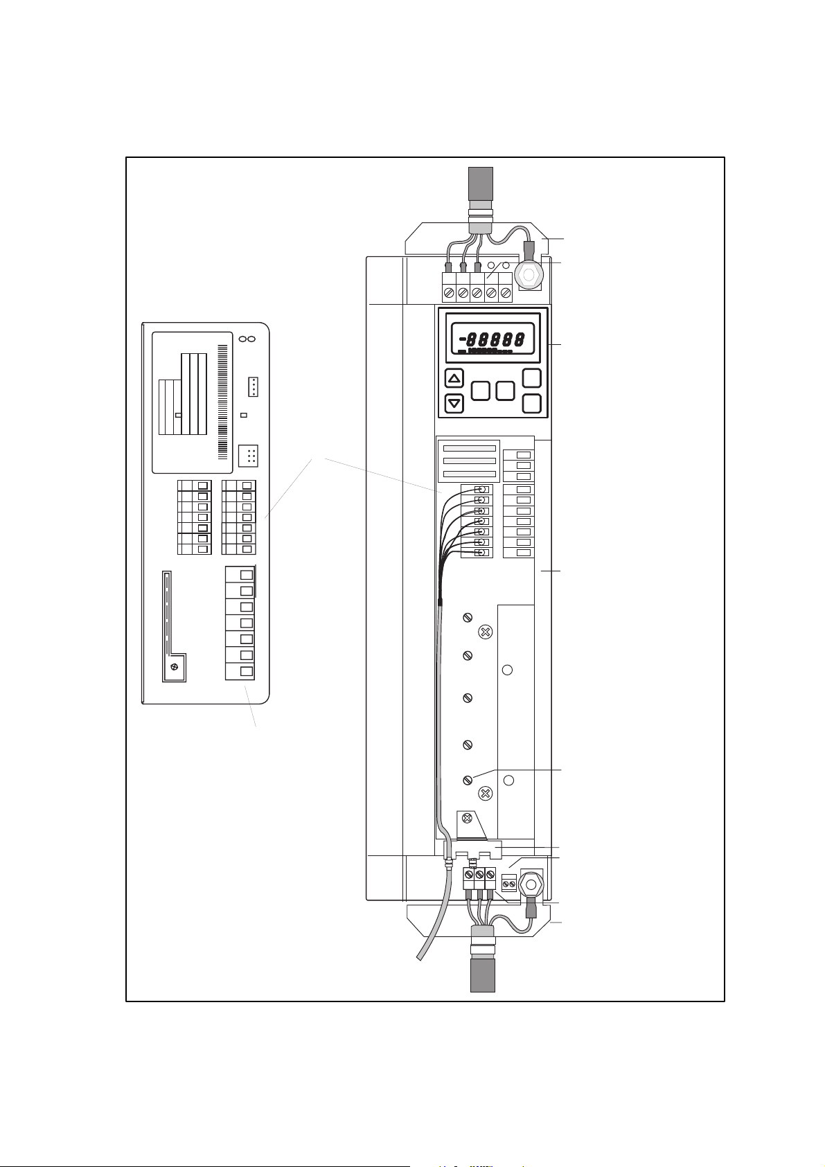
Screen-sheet m ains connection
M ains connection and
D C connection
PE
A
%
D etachable operating m odule,
Hz
as alternative
STP
RUN
Fieldbus
INTERBUS
Typ
Id .-N R
F e rt.- N r
Serien-Nr.
Eingang1
Eingang2
C ontrol Term inals
62
7
8
9
K12
K21
K22
K24
20
E1 28
E2
E3
K11
E4
39
K14
C ontrol term inals
M ains-/M otor connection
Screen connection
Screen-sheet control connections
PE
Therm al-contact connection
W
U
V
UVW
T1 T2
M otor connection
Screen-sheet m otor cables

Contents
Show/Hide Bookmarks
Part A
1 Preface and general information 1-1...............................
1.1 Howto use this Manual 1-1...........................................
1.1.1 Terminology used 1-1.......................................
1.2 Scope of delivery 1-1................................................
1.3 Legalregulations 1-3................................................
1.4 ECDi rectives/D eclarationofConformity 1-4................................
1.4.1 What is the purpose of EC directives? 1-4.........................
1.4.2 What does the CE mark imply? 1-4.............................
1.4.3 EC Low-V oltage Directive 1-5.................................
1.4.4 EC Directive Electromagnetic Compatibility 1-7.....................
1.4.5 ECMachi neryDirect i ve 1-11...................................
2 Safety i nformation 2-1..........................................
2.1 Generalsaf etyin formation 2-1.........................................
2.2 Layout of the safety information 2-2.....................................
2.3 Residualhazards 2-2................................................
8200SHB0199
i

Contents
Show/Hide Bookmarks
Part B
3 Technical data 3-1.............................................
3.1 Overview of types 3-1...............................................
3.2 Featu res 3-2......................................................
3.3 General data/application conditions 3-4...................................
3.4 Rated data (Operation with 150 % overload) 3-5.............................
3.4.1 Types8201 to8204 3-5.....................................
3.4.2 Types8211 to8214 3-6.....................................
3.4.3 Types8215 to8218 3-8.....................................
3.4.4 Types8221 to8224 3-10.....................................
3.4.5 Types8225 to8227 3-12.....................................
3.4.6 Types8241 to8243 3-14.....................................
3.4.7 Types8244 to8246 3-16.....................................
3.5 Rated data (Operation with 120 % overload) 3-18.............................
3.5.1 Operating conditions 3-18.....................................
3.5.2 Types821X 3-18...........................................
3.5.3 Types822X 3-19...........................................
3.5.4 Types824X 3-20...........................................
3.6 Fusesandcabl ecross-sections 3-21.....................................
3.6.1 Operation of controllers in UL-approved systems 3-21.................
3.6.1.1 Protectionof th emotorcabl es 3-21...................
3.6.2 Si ngl ed r i ves w i t h150 %ov er l oad 3-22...........................
3.6.3 Si ngl ed r i ves w i t h120 %ov er l oad 3-23...........................
3.7 Analog plug-in module 8279I B 3-24......................................
3.7.1 Features 3-24.............................................
3.8 Dim ensions 3-25....................................................
3.8.1 Analog plug-in module 3-25...................................
8200SHB0199ii

Contents
Show/Hide Bookmarks
4 Installation 4-1................................................
4.1 Mechanical installation 4-1............................................
4.1.1 Important notes 4-1........................................
4.1.2 Standard assembly with fixing rails or fixing brackets 4-3..............
4.1.2.1 Types 8201 to8204 4-3..........................
4.1.2.2 Type 8202-V002(reduc edassem blydept h) 4-3..........
4.1.2.3 Types 8211 to8214 4-4..........................
4.1.2.4 Types 8215 to8218 4-5..........................
4.1.2.5 Types 8221 to8227 4-6..........................
4.1.2.6 Types 8241 to8246 4-7..........................
4.1.3 DIN-railass embl y 4-8.......................................
4.1.3.1 Types 8201 to8204 4-8..........................
4.1.3.2 Types 8211 to8214 4-9..........................
4.1.4 Assemblywith thermally separated power stage
(”push-through technique”) 4-10................................
4.1.4.1 Types 8215 to8218 4-11..........................
4.1.4.2 Types 8221 to8227 4-12..........................
4.1.4.3 Types 8241 to8246 4-13..........................
4.1.5 Assemblyofthe vari an t82XX-V003”coldplate” 4-14.................
4.1.5.1 General 4-14...................................
4.1.5.2 Demandsonthe cooler 4-15........................
4.1.5.3 Thermal performance of the system 4-16...............
4.1.5.4 Assemb l ypr ep ar ations 4-17........................
4.1.5.5 Assemb l yof821X-C-V003 4-18.....................
4.1.5.6 Assemb l yof822X-C-V003 4-21.....................
4.1.5.7 Assemb l yof824X-C-V003 4-22.....................
4.1.6 Assemblywi thm ainsfilter 4-23.................................
4.1.7 Assembly of the analog plug-in module 8279IB 4-24..................
4.2 Electrical in stallation 4-25.............................................
4.2.1 Oper ator’ ssafety 4-25.......................................
4.2.2 Pr otecti ono fthe controll ers 4-26...............................
4.2.3 Motor protection 4-26.......................................
4.2.4 Mains types/mains conditions 4-27..............................
4.2.5 Combination with compensation equipment 4-27.....................
4.2.6 Specification of the cables used 4-27.............................
4.2.7 Power connections 4-28......................................
4.2.7.1 Mains connection 4-28............................
4.2.7.2 Motor connection 4-29............................
4.2.7.3 Connection of a brake unit 4-34......................
4.2.7.4 Connection plan 820X 4-35.........................
4.2.7.5 Connection plan 821X 4-36.........................
4.2.7.6 Connection plan 822X/824X 4-37....................
4.2.8 Control connections 4-38.....................................
4.2.8.1 C ontrolcables 4-38..............................
4.2.8.2 Assignment of the control terminals 4-38...............
4.2.8.3 Connection diagrams 4-41.........................
4.2.8.4 Connection diagrams: Analog plug-in module 4-42........
4.3 Installation of a CE-typical drive system 4-43................................
8200SHB0199
iii

Contents
Show/Hide Bookmarks
Part C
5 Commissioning 5-1............................................
5.1 Before switching on 5-1..............................................
5.2 Short commissioning (factory setting) 5-2..................................
5.2.1 Switch-on sequence 5-2.....................................
5.2.2 Factory setting of the most important drive parameters 5-2............
5.3 Adapt machine data 5-3..............................................
5.3.1 Determine speed range (fdmin, fdmax) 5-3........................
5.3.2 Settingofacceleration andd eceler ationtimes( Tir, Tif) 5-4.............
5.3.3 Setting of current limit values (I maxlimits) 5-5......................
5.4 Optimisation of the operating behaviour 5-6................................
5.4.1 Select control mode 5-6.....................................
5.4.2 Optimising operating modes 5-8...............................
5.4.2.1 Optimising motor-current control (C014 = -4-) 5-8.......
5.4.2.2 Optimise V/f-characteristic control with auto boost
(C014 = -0-/-1-) 5-10............................
5.4.2.3 Optimise V/f-characteristic control with constant Vmin boost
(C014 = -2-/-3-) 5-12............................
5.4.2.4 Norm alisationofan application datum 5-15.............
5.4.3 Operation with PIDcontroller 5-16...............................
5.5 Ap plication examples for PI Dcontrollers 5-18................................
5.5.1 Pumpapplication with pressure control 5-18........................
5.5.2 Pum papplication with level control 5-21...........................
5.5.3 Dancer-position control ( line drive) 5-23...........................
5.5.4 Air conditioning system 5-26...................................
6 During operation 6-1...........................................
6.1 Operating information 6-1............................................
6.1.1 General 6-1..............................................
6.1.2 822X /824X 6-2...........................................
6.1.3 8218-V003 6-2...........................................
6.2 Display of the controller status 6-2......................................
8200SHB0199iv

Contents
Show/Hide Bookmarks
Part D
7 Configuration 7-1..............................................
7.1 8201BB operatingmodule 7-2.........................................
7.2 Structure of the operating program 7-4...................................
7.2.1 Oper ati nglevel 7-4........................................
7.2.2 Code level 7-4............................................
7.2.3 Parameterlevel 7-5........................................
7.3 Change and store parameters 7-5.......................................
7.3.1 Chan ge andstor eparameter swi t hthe8201BB operatingmodule 7-6.....
7.3.2 Change and store parameters with fieldbus modules. 7-8..............
7.3.3 Dynamic parameter change 7-8...............................
7.4 Operating functions 7-9..............................................
7.4.1 Operating mode 7-9........................................
7.4.2 Working with parameter sets 7-10...............................
7.4.3 Change parameter set via DC-bus voltage 7-12.....................
7.4.3.1 AC-motorbrakingbymeansofparameter setch angeover 7-12
7.4.3.2 Automatic parameter set changeover for controlled
deceleration in the event of mains failure 7-13...........
7.5 Control functions 7-15................................................
7.5.1 Speed range (fdmin, fdmax) 7-15...............................
7.5.2 Accelerationanddecelerat iontimesTi r, Tif 7-16.....................
7.5.3 Current limit values (I m ax limitvalues) 7-17........................
7.5.4 Current limitation controller (I m ax controller) 7-18....................
7.5.5 Control m ode 7-19.........................................
7.5.6 V /fch ar act eristi c 7-22.......................................
7.5.6.1 V /f-ratedfreq uencyfdr 7-22........................
7.5.6.2 V minsetti ng 7-24................................
7.5.7 Configuration 7-26..........................................
7.5.8 Motor data detection 7-27....................................
7.5.9 Running optimisation 7-28....................................
7.5.9.1 Sl i pcompensati on 7-28...........................
7.5.9.2 Chopper frequency 7-29...........................
7.5.9.3 Oscillation damping 7-31..........................
7.5.9.4 Ramp function generator S-shape 7-32................
7.5.9.5 Ski pfreq uenci es 7-33.............................
7.5.10 PIDcont rol l eras processcont rol l er 7-34..........................
7.5.10.1 R eset integral component and influence 7-38............
7.5.10.2 Setpoint selection for the process controller 7-38..........
7.5.10.3 Frequency precontrol 7-39.........................
7.5.10.4 Fr equen cysett i ngrange 7-39.......................
7.5.11 Setpoint input 7-40.........................................
7.5.11.1 Analog setpoint input 7-40.........................
7.5.11.2 Setpoint input using the keypad 7-42..................
7.5.11.3 Setpoint input via JOG frequencies 7-43................
7.5.11.4 Setpoint input via function ”Motor potentiometer” 7-44......
7.5.11.5 Setpoint input via of the function ”Motor potentiometer in
combin ation withJOG value” 7-46....................
7.5.11.6 Setpoint su m 7-47...............................
8200SHB0199
v

Contents
Show/Hide Bookmarks
7.5.12 Con t r ollerenabl e RFR 7-48....................................
7.5.13 Start conditions/flying-restart circuit 7-49..........................
7.5.14 Function of the inputs to be configured block by block 7-50.............
7.5.14.1 Level inversion for digital inputs 7-52..................
7.5.14.2 Priority mask for digital inputs 7-53...................
7.5.14.3 Change of the direction of rotation (CW/CCW) 7-54........
7.5.14.4 Q uickstopQS P 7-55.............................
7.5.14.5 DC-in jectio nbr ake(DCB) 7-56.......................
7.5.14.6 Parametersetchan geov erPAR 7-58..................
7.5.14.7 TRIPset 7-58..................................
7.5.14.8 Manual/rem ote chan geover 7-59.....................
7.5.14.9 Digital frequency input 7-60.........................
7.5.15 In direct torque limitation 7-61..................................
7.6 Display functions 7-62................................................
7.6.1 Displ ayvalues 7-62.........................................
7.6.2 Switch-on display 7-62.......................................
7.6.3 Normalisation of an application datum 7-63........................
7.6.4 Elapsed operating time meter 7-64..............................
7.6.5 Software versionandcontrollertype 7-64..........................
7.7 Monitoring functions 7-65.............................................
7.7.1 Relay outputs 7-65.........................................
7.7.2 Analog output 7-69.........................................
7.7.3 Thermal motor monitoring 7-71.................................
7.7.3.1 I 2x t monitorin g 7-71.............................
7.7.3.2 PTC input 7-72.................................
7.7.4 Motor-phase failure detection 7-73..............................
Part D1
7.8 Code table for “Standard” series 7-77.....................................
Part D2
7.9 Code table for “HV AC” series 7-85.......................................
8200SHB0199vi

Contents
Show/Hide Bookmarks
Part E
8 Troubleshooting and fault elimination 8-1...........................
8.1 T roubleshooting 8-1.................................................
8.1.1 Display at the controller 8-1..................................
8.1.2 Display at the operating module 8-1.............................
8.1.3 Maloperation of the drive 8-2.................................
8.2 Fault analysis wi ththe historybuffer 8-2..................................
8.3 Fault messages 8-2.................................................
8.4 Reset of fault messages 8-4...........................................
9 Maintenance 9-1..............................................
9.1 Maintenance services 9-1............................................
9.2 Service addresses 9-2...............................................
Part F
10 Network of several drives 10-1....................................
10.1 Funct i on 10-1......................................................
10.2 Conditions for trouble-free network operation 10-2............................
10.2.1 Possible combinations 10-2...................................
10.2.2 Mains connection 10-3.......................................
10.2.2.1 C ab le protection/cab l ecross-section 10-3..............
10.2.2.2 Main scho k e/m ainsfilter 10-3.......................
10.2.2.3 C ont r ollerprotection 10-3..........................
10.2.3 DC-bus connection 10-4......................................
10.2.4 Fusesandcablecro ss-sections fo ra networ kofseveraldr iv es 10-6.......
10.2.5 Prot ection innetworksofs everaldri ves 10-7.......................
10.3 Selecti onbasics 10-9................................................
10.3.1 Conditions 10-9............................................
10.3.2 Selecti onexample fo r4 drives 10-12..............................
10.3.2.1 Supplyonly via controllers 10-12......................
10.3.2.2 Supplyby means of 934Xsupply and feedback module 10-13.
10.4 Central supply 10-14..................................................
10.4.1 Central supply of 820X 10-14...................................
10.4.2 Central supply via 934Xfor821X/822X /824X/93XX 10-15...............
10.5 Decentral supply 10-16................................................
10.5.1 Decentral supply for 820X 10-16.................................
10.5.2 Central supply for 821X/822X /824X/93X X/934X 10-17.................
See also table of contents of the attached Operating Instructions
8200SHB0199
vii

Contents
Show/Hide Bookmarks
Part G
11 Application of brake units
See: Table of contents of the attached Operating Instructions
Part H
12 Automation
See: Table of contents of the attached Operating Instructions
Part I
13 Accessories (Survey) 13-1........................................
13.1 Access oriesforall ty pes 13-1...........................................
13.2 Softw ar e 13-1.....................................................
13.3 Type-specificaccessories 13-2..........................................
13.3.1 T ypes820X 13-2...........................................
13.3.2 T ypes821X 13-3...........................................
13.3.3 T ypes822X 13-4...........................................
13.3.4 T ypes824X 13-5...........................................
Part K
14 Selection help 14-1.............................................
15 Application examples 15-1.......................................
15.1 Pum papplicationwithpressure control 15-1................................
15.2 Pum papplication with level control 15-4...................................
15.3 Dancer-positioncontrol(line drive) 15-6....................................
15.4 Air conditioning system 15-8...........................................
8200SHB0199viii

Contents
Show/Hide Bookmarks
Part L
16 Signal-flow charts 16-1..........................................
16.1 Sig nal-flowchartfortypes820X 16-2.....................................
16.1.1 Con t r olst r uctu r e 16-2.......................................
16.1.2 Inver t ercon trol 16-3........................................
16.1.3 Mo nitorings 16-3...........................................
16.2 Sig nal-flowchartsfortypes 821X/822X/824X 16-4............................
16.2.1 Control structure control mode V/f control 16-4......................
16.2.2 Control structure control mode motor current control 16-5..............
16.2.3 Inver t ercon trol 16-6........................................
16.2.4 Mo nitorings 16-6...........................................
16.3 Sig nal-flowchartsfortypes 821X/822X/824X-H VAC 16-7.......................
16.3.1 Processandspeedco ntroll erforC005 = -0- 16-7...................
16.3.2 Processandspeedco ntroll erforC005 = -1- ... -7- 16-8...............
Part M
17 Gl ossary 17-1..................................................
18 Table of keywords 18-1..........................................
8200SHB0199
ix

Contents
Show/Hide Bookmarks
8200SHB0199x

EDS8200U--A
Show/Hide Bookmarks
00406181
Manual
Part A
Table of contents
Preface and general information
Safety information
= G l obal Drive
Frequ ency inv erters 8200

This Manual is valid for 82XX controllers as of version:
Show/Hide Bookmarks
33.820X- E - 1x. 1x (8201- 8204)
33.8202- E- 1x. 1x -V002 Redu c edassem blydep t h(8202)
33.821X- E - 0x. 1x (8211- 8218)
33.821X- E - 1x. 2x (8211- 8218)
33.821X- C- 1x. 2x -V003 Coldplate(8215- 8218)
33.821X- E - 3a. 3x -V020 HVAC (8211 - 8218)
33.822X- E - 0x. 0x (8221- 8227)
33.822X- C- 1x. 2x -V003 Coldplate(8221- 8222)
33.822X- E - 3a. 3x -V020 HVAC (8221 - 8227)
33.824X- E - 1x. 1x (8241- 8246)
33.824X- C- 1x. 1x -V003 Coldplate(8241- 8246)
33.824X- E - 3a. 3x -V020 HVAC (8241 - 8246)
Type
Design:
B = Module
C= Coldplate
E = Built-in unitIP 20
Hardware version and index
Softwareversionandindex
Variant
Explanation
Edition of: 01/1999
revised
Preface and general information
Show/Hide Bookmarks
1 Preface and general information
1.1 How to use this Manual
- This Manual completes the Operating Instructions for 82XXfrequency
inverters.
- It contains the Operating Instructions and additional information on planning,
adaptability and the accessories valid at the time of printing.
- In case of doubt, refer to the Operating Instructions delivered with the
82XXfrequency inverters.
- The Manual is a help to select and adapt the 82XXfrequency inverters and
the accessories to ensure safe and trouble-free operation. It contains safety
information which must be observed.
- The Manual must always be in a complete and perfectly readable state.
1.1.1 Terminology used
Term In the following text used for
82XX Anyfrequencyinvert erof the series8200, 8210, 8220, 8240
Controllers 82XX frequency inverter
Drive system Driv esystem swith82XXfrequencyinvertersand other Lenze drivecomp o nen ts
1.2 Scope of delivery
Scope of delivery Important
-
1 82XXfrequency inverter
-
1 Operating Instructions
-
1 accesso rykit (comp o n en tsandpieces
fo rmechanicalandelectricalinstallation)
Afterrecepti onofthedelivery, checkim mediatelywhetherthe scope
of supply matches the accompanying papers. Lenze does not accept
anyliability for deficiencies claimedsubs equ ently.
Claim
-
visible transport damage immediately to the forwarder.
-
visib ledeficiencies/incom pletenessimmediatelytoyou rLenze
rep resent ative.
8200SHB0199
1-1
Preface and general information
Show/Hide Bookmarks
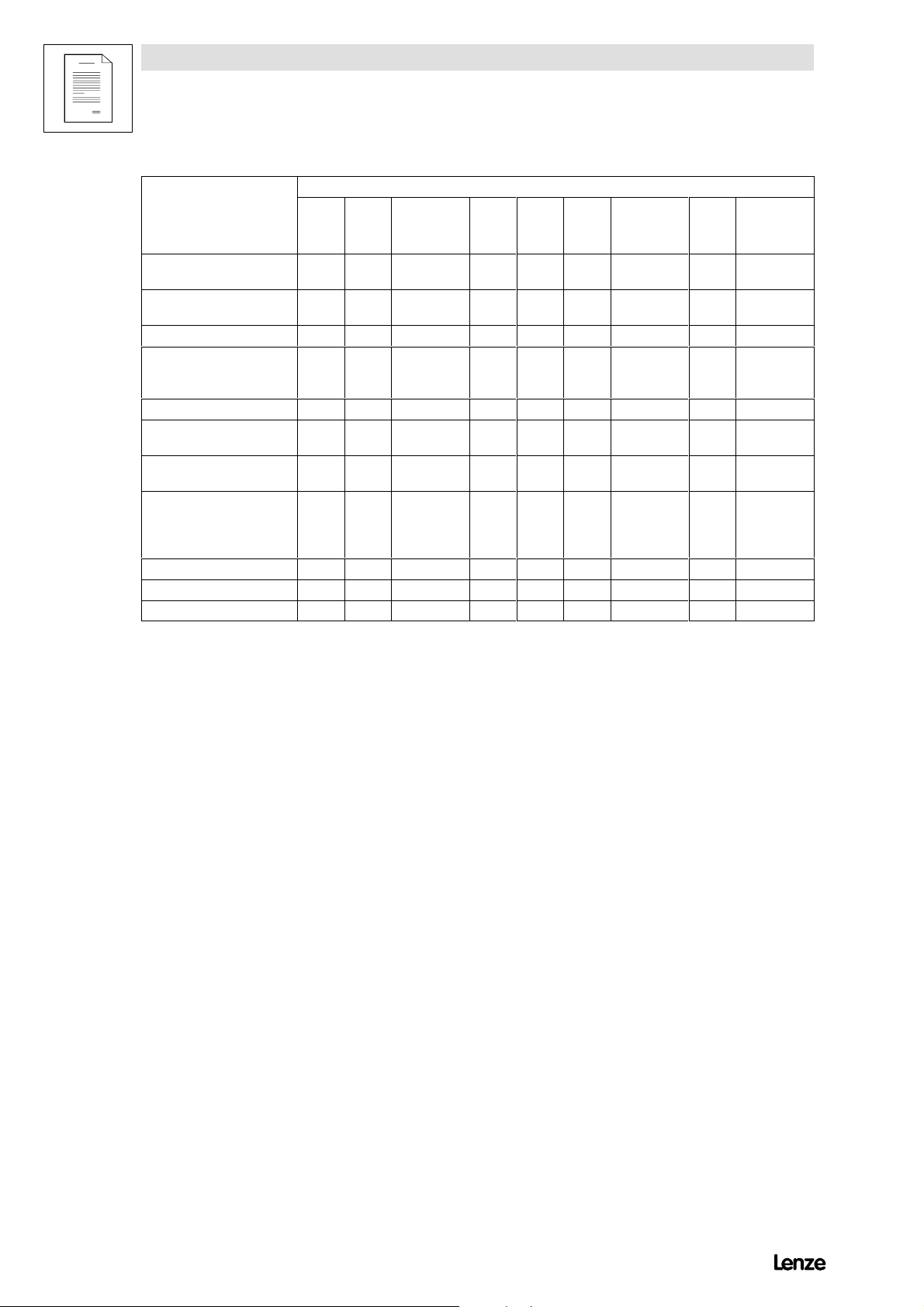
Accessorykit
820X 821X 821X-V003 8221
8222
8223
7-pole socket connectors for
contr o lcables
3-pole socket connectors for
relay output K2
Fixingrails 2 2 2 - - - - 2 Fixing units incl. screws for
fixingthe inverter tothe
housing
PGdiaphragm gland 21 - - - 1 1 1 1 - Screensheetfo rcont rol
cables incl. fixingscrew
Screensheetfo rmo t orcable
incl. two fixing screws
Hexagon nuts incl. washers
and spring-lock washers for
the electrical connectio nof
thepowerstage
Heat-conducting paste - - 1 tube - - - 1 tube - 1 tube
Gasket - - 1 - - - 1 - 1
Tightening frame - - 1 - - - 2 - 2
2 2 2 2 2 2 2 2 2
- - - 1 1 1 1 1 1
- - - 4 4 - - - -
- - - 1 1 1 1 1 1
- - - 1 1 1 1 1 1
- - - 8M6 8M8 8M10 8M6 - -
8224
8225
8226
8227
8221-V003
8222-V003
824X 824X-V003
8200SHB01991-2
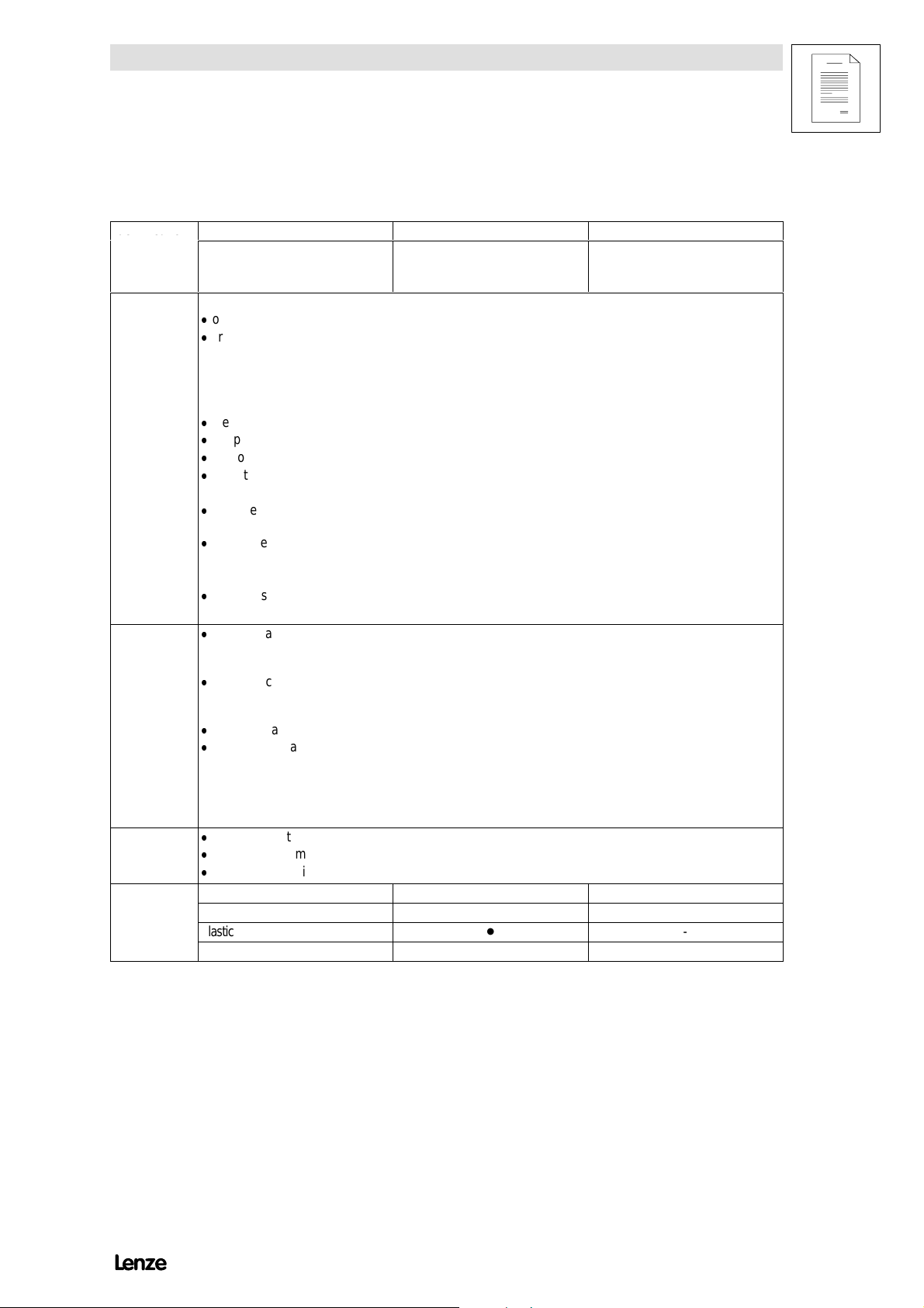
1.3 Legal regulations
Identificatio
n
Disposa
l
Show/Hide Bookmarks
Preface and general information
Identification
Application
as directed
Liability
Warranty
Disposal
Nameplate CE-identification Manufacturer
Lenze controllers are unambiguously
designated bythe contents of the
nameplate.
Conforms to the EC Low Voltage
Directive
Lenze GmbH &Co KG
Postfac h101352
D-31763Hameln
82XX frequency inverter
-
operate the controller only under the conditions prescribed in these operating instructions.
-
are components
- foropenandclo sedloopedco ntrol ofvariable speeddriveswithasynchro nous standardm otors,relu c t ance
motors, PMsynchronous motors with asynchronous damper cage,
- for installation into a machine,
- used for assembly together with other components to forma machine.
-
are electric units for the installation into control cabinets or similar enclosed operating housing.
-
comply with the requirements of the Low-Voltage Directive.
-
are not machines for the purpose of the Machinery Directive.
-
are not to be used as domestic appliances, but only for industrial purposes.
Drivesystems with 82XX frequency inverters
-
meetthe ECElectrom agn etic Comp atibilityDirective ifthey are installed accordin gto the guidelinesof CE-typical
drive systems.
-
can be used
- on public and no n-pu b licmains,
- in industrial as well as residential and commercial premises.
-
The user is responsible for the compliance of his application with the EC directives.
Any other use shall be deemed inappropriate!
-
The information, data, and notes in these instructions met the state of the art at the time of printing. Claims on
m odif icatio nsreferringto cont roll erswh i chhavealread ybeensuppli edcannot be derivedfromtheinformation,
illustratio n s,and description s.
-
The specifications, processes, and circuitry described in these instructions are for guidance only and mustbe
adapted to yo u row nspecific application. Lenze doesnottake respo n sib ilityfor thesuitabilityof the pro cessand
circuit proposals.
-
The specifications in these instructions describe the product features without guaranteeing them.
-
Lenzedoesnotaccept anyliabilityfordamageand operatinginterference causedby:
- disregarding the operating instructions
- unauthorised modifications to the controller
- operating errors
- improper working onand with the controller
-
Warrantyco ndit i ons :SeeSalesandDeliveryCond i tionsofLenze G mbH&Co KG .
-
Warrantyclaims mustbe made toLenze immediatel yafterdetecti ngthedefici encyorfault.
-
Thewarrantyisvoidin all cases w hereliability claims cannot be mad e.
Material Recycle Dispose
Metal - Plastic - Assembled PCBs - -
8200SHB0199
1-3

Preface and general information
Show/Hide Bookmarks
1.4 EC Directives/Declaration of Conformity
1.4.1 What is the purpose of EC directives?
EC directives are issued by the European Council and are intended for the
determinationofcommon technicalrequirements (harmonisation)and certification
procedures within the European Community. A t the moment, there are 21 EC
directivesofproduct ranges.Thedirectivesareor willbeconverted to nationallaws
of the member states. A certification issued by one member state is valid
automatically without any further approval in all other member states.
The texts of the directive are restricted to the essential requirements. Technical
details are or will be determined by European harmonised standards.
1.4.2 What does the CE mark imply?
After a verification, the conformity according to the EC directives is certified by
affixing a CE mark. Within the EC there are no commercial barriers for a product
withthe CEmark.
The enclosure of a conformity certification is not necessary according to most
directives. Therefore, the customer is not able to appreciate which of the 21 EC
directivesapplies to a product andwhichharmonised standardsareconsidered
in the conformity verification.
Controllers on their own with the CE mark exclusively correspond to the Low
Voltage Directive. For the compliance with the EMC Directive only general
recommendations have been issued so far. The CE conformity of the installed
machine remains the responsibility of the user. For the installation of CE-typical
drivesystems,LenzehasalreadyprovedtheCEconformitytotheEMCDirective.
8200SHB01991-4

Preface and general information
Show/Hide Bookmarks
1.4.3 EC Low-Voltage Directive
(73/23/EEC)
amended by: CE Mark Directive (93/68/EEC)
General
- The Low-Voltage Directive is effective for all electrical equipment for use
with a rated voltage between 50 V and 1000 V AC and between 75 V and
1500 V DC, and under normal ambient conditions. The use of e.g. electrica l
equipment in explosive atmospheres and electrical parts in passenger and
goods lifts are excepted.
- The objective of the Low Voltage Directive is to ensure that only electrical
equipment which does not endanger the safety of persons or animals is
placed on the market. It should also be designed to conserve material
assets.
8200SHB0199
1-5
Preface and general information
Show/Hide Bookmarks
EC Declaration of Conformity ’95
for the purpose of the EC Low-Voltage Directive (73/23/EEC)
amended by: CE Mark Directive (93/68/EEC)
820X/821X/822X/824X controllers are developed, designed, and manufactured
incompliance with the abovementioned ECDirective under thesole responsibility
of
Lenze GmbH & Co KG, Postfach 10 13 52, D-31763 Hameln
Standards considered:
Standard
DINV DE0160 5.88 +A1/ 4.89 +A2 /10.88
DINEN50178
Classificati onVDE0160 / 11.94
DINV DE0100 S tand ardsfor theinstallation of powerinstallations
EN60529 IP degrees of protection
IEC 249 / 1 10/86, IEC249 / 2-15 / 12/89 Base material for printed circuits
IEC 326 / 1 10/90, EN60097 / 9.93 Prin tedcircuits, printed boards
DINV DE0110 /1-2 /1/89 /20/ 8/90 Creepacedistancesandclearan c es
Electronic equipment for use in electrical power
installations
Hameln, 01 October, 1995
________________
(i.V.Loy)
Product Manager
8200SHB01991-6

Preface and general information
Show/Hide Bookmarks
1.4.4 EC Directive Electromagnetic Compatibility
(89/336/EEC)
amended by: F irst Amendment Directive (92/31/EEC)
CEMark Directive(93/68/EEC)
General
- The EC Electromagnetic Compatibility Directive is effective for ”devices”
which may cause electromagnetic interference or the operation of which
may be impaired by such interference.
- The aim is to limit the generation of electromagnetic interference so that an
operation without interference to radio and telecommunication systems and
other equipment is possible. The devices must also show an appropriate
resistance against electromagnetic interference to ensure the application as
directed.
- Controllers cannot be driven in stand-alone operation and therefore the
controllers cannot be evaluated on their own in terms of EMC. Only after the
integration of the controllers into a drive system, can this system be tested
concerning the objectives of the EC EMC Directive and the compliance with
the ”Law about the Electromagnetic Compatibility of Devices”.
- Lenze has verified the conformity of controllers integrated into certain
defined drive systems. In the following these systems are called ”CE-typical
drivesystems”.
The following configurations can now be selected by the user:
- The user himself can determine the system components and their
integration into the drive system and is then held responsible for the
conformityof the drive.
- The user can select the CE-typcial drive systems for which the
manufacturer has already proved the conformity.
8200SHB0199
1-7
Preface and general information
Show/Hide Bookmarks
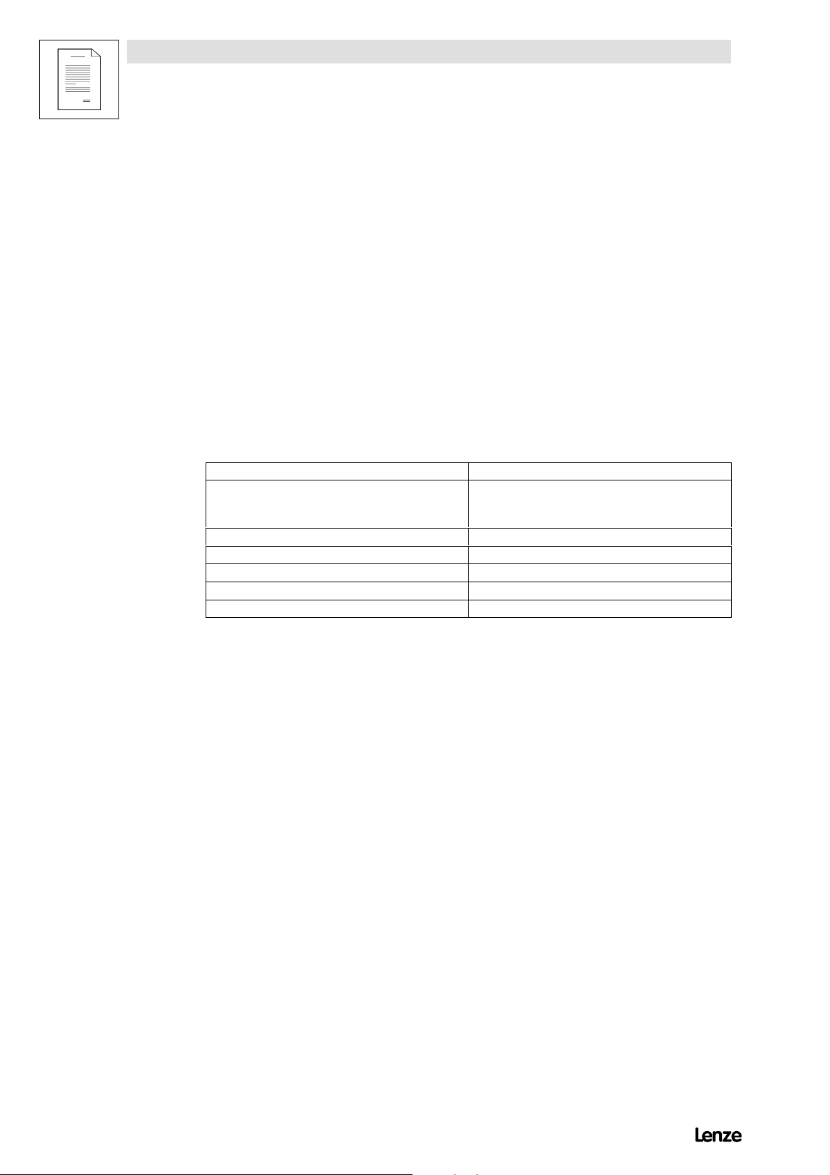
Components of the CE-typical drive system
System component Specification
Contr o ller 820X/821X/822X/824Xcontro l l er s
For type designation see inner cover page
RFIfilter For data and data assignment, see chapter ”Accessories ”
Mains choke For data and data assignment, see chapter ”Accessories”
Mainsfilters For data and data assignment, see chapter ”Accessories”
Motor cable Screenedpowercable withtinned E-CUbraidwitha m inimumof 85 % optical
Mainscable betw eenRFIfilter
and controller
Contr o lcables Screen edsignal cable typeLIYCY
Motor Standard three-phase AC asynchronous motor
Accesso r ies Forratedaccessories ,seeinnercoverpage.
- Controller, RFI filter and mains choke are mounted on one assembly board.
cov erag e
As fromcable length 300 mm:
Screenedpow ercable withtinnedE-CUbraid witha minimumof 85 % optical
cov erag e
Lenzetype DXRA or similar
- The system components are functionally wired according to chapter 4,
”Electrical installation”.
Application as directed/Scope of application
- The820X/821X/822X/824X controllers areintended for the useincontrol
cabinets.
- The820X/821X/822X/824X controllers aredirected as components for the
control of variable-speed drives with three-phase AC motors to be
assembled together with other components to form a drivesystem.
The drive systems are intended for installation into a machine or for the
constructiontogetherwith other components to form a machine or a plant.
- Drive syste mswith the 820X/821X/822X/824X controllers, which are
installed according to the guidelines of CE-typical drive systems,
correspond to the EC EMC Directive and the standards mentioned below.
- The CE-typical drive systems are suitable for the operation on public and
non-public mains.
- The CE-typical drive systems are provided for the operation in industrial
premises as well as in residential and commercial areas.
- Because of the earth-potential reference of the RF I filters, the described
CE-typical drive systems are not suitable for the connection to IT-mains
(mains without earth-reference potential).
8200SHB01991-8
- The controllers are not domestic appliances, but they are intended as a part
of drivesystems for commercialuse.
Preface and general information
Show/Hide Bookmarks
EC Declaration of Conformity ’95 for the purpose of the EC
Directive
on Electromagnetic Compatibility (89/336/EEC)
amended by: F irst Amendment Directive (92/31/EEC)
CEMark Directive(93/68/EEC)
820X/821X/822X/824Xcontrollerscannot be driven in stand-alone operation for
the purpose of the R egulation about Electromagnetic Compatibility (EMVG of
9/11/92 and 1. EMVGÄndG of 08 August, 1995). The EMC can only be verified
when thecontroller isintegrated into a drive system.
Lenze GmbH & Co KG, Postfach 10 13 52, D-31763 Hameln
declaresthat thedescribed ”CE-typicaldrivesystems” withthe controllersof the
types 820X/821X/822X/824X comply with the above mentioned EC Directive.
Theconformity evalua tion is based on the working paper of the product standard
for drive systems:
IEC 22G-W G4 5/94 EMC product standard including specific test methods for power drive systems”
Generic standardsconsidered:
Generic standard
EN50081-1 /92 Generic standard for the emission of noise
Part 1: Residential area, commercial premises, and small businesses
EN50081-2 /93
(u sedinadditionto the
requirements of IEC 22G)
prEN50082-2 3/94 Generic standard for noise immunity
Generic standard for the emission of noise
Part 2: Industrial premises
The emission of noise in industrial premises is not limited in IEC 22G.
Part 2: Industrial premises
The requirements of noise immunity for residential areas were not considered
since they are less strict.
8200SHB0199
1-9
Preface and general information
Show/Hide Bookmarks
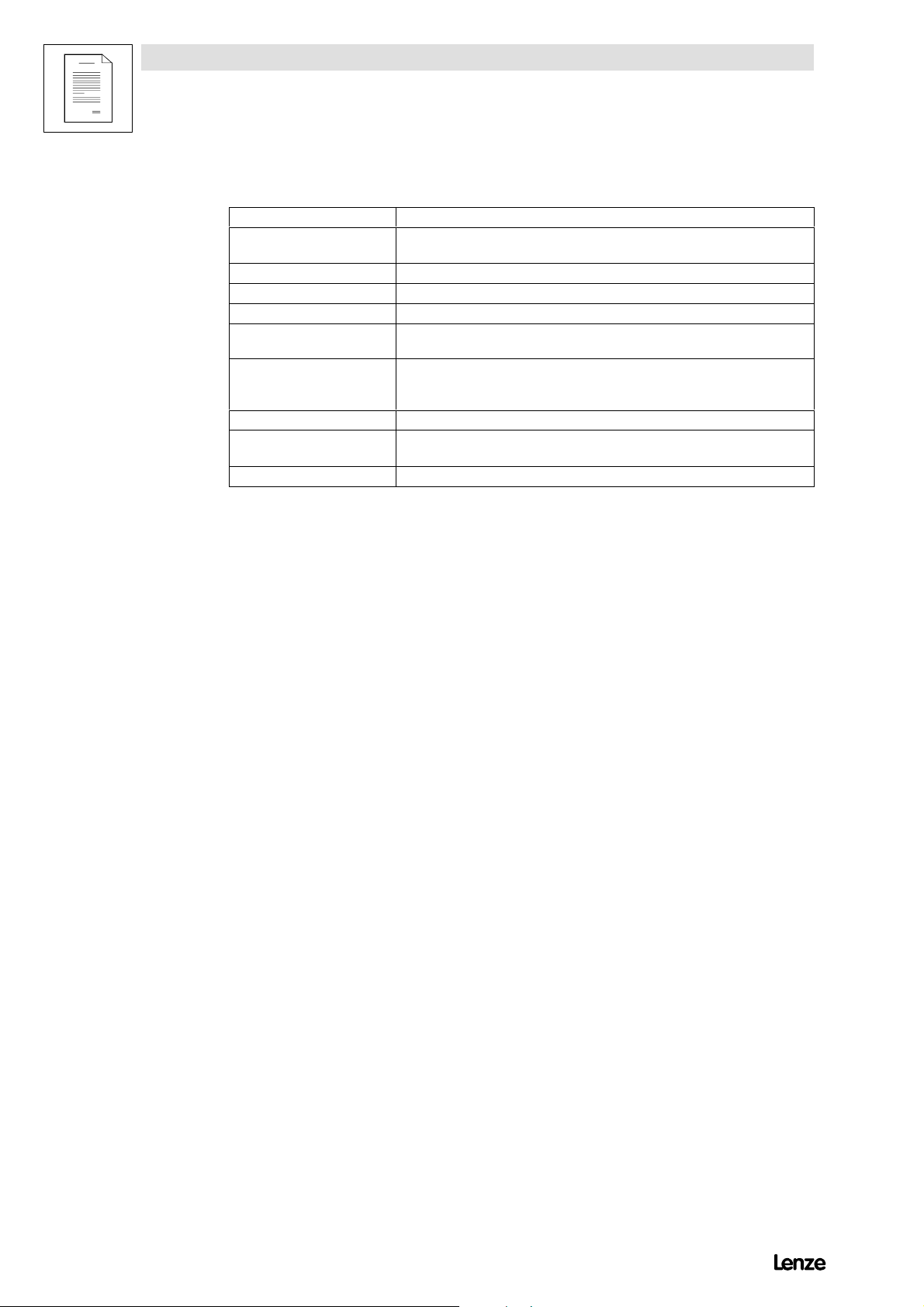
Considered basic standards for the test of noise emission:
Basic standard Test Limit value
EN55022 7/92 R adio interference housing and mains
EN55011 7/92
(u sedinadditionto the
requirements of IEC 22G)
IEC 801-2 /91 Electrostatic discharge
IEC 1000-4-3 Electromagnetic fields
ENV50140 /93 High-frequency field
IEC 801-4 /88 Fast transients
IEC 801-5 Surge test
Freq uencyrange0.15 - 1000MHz
Radio interference housing and mains
Freq uencyrange0.15 - 1000MHz
The emission of noise in industrial premises is not
limitedin IEC22G.
on housing and heat sink
Freq uencyrange26 - 1000 MHz
Freq uencyrange80 - 1000 MHz,
80 % amplitude modulated
Fixed frequency
900 MH zwith200 Hz, 100 %modulated
burst on power terminals
Burst on bus and control cables Severity 4
Mainscables
Class B
for use in residential areas
and commercial premises
Class A
foruse in
industrial premesis
Severity 3
6 kV with contact discharge
8 kV air discharge
Severity 3
10 V/m
Severity 3
10 V/m
10 V/m
Severity 3
2kV/5kHz
2kV/5kHz
In stallatio nclass 3
Hameln, 01 October, 1995
________________
(i.V.Loy)
Product Manager
8200SHB01991-10

Preface and general information
Show/Hide Bookmarks
1.4.5 EC MachineryDirective
(89/392/EEC)
amended by: First Amendment Directive(91/368/EEC)
Second Amendment Directive (93/44/EE C)
CEMark Directive(93/68/EEC)
General
For the purpose of the Machinery Directive, ”machinery” means an assembly of
linked parts or components, at least one of which moves, with the appropriate
actuators, control and power circuits, etc., joined together for a specific
application, in particular for the processing, treatment, moving or packaging of a
material.
8200SHB0199
1-11

Preface and general information
Show/Hide Bookmarks
EC Manufacturer’s Declaration
for the purpose of the EC Machinery Directive (98/392/EEC)
amended by: First Amendment Directive (91/368/EE C)
Second Amendment Directive (93/44/EE C)
CE Mark Directive (93/68/EEC)
The 820X/821X /822X/824X controllers were developed, designed, and
manufactured under the sole responsibility of
Lenze GmbH & Co KG, Postfach 10 13 52, D-31763 Hameln
Commissioning of the controllers is prohibited until it is proven that the machine
in which they are to be installed corresponds to the EC Machinery Directive.
Hameln, 01 October, 1995
________________
(i.V.Loy)
Product Manager
8200SHB01991-12
2 Safety information
Show/Hide Bookmarks
2.1 General safety information
Safety and application notesfor controllers
(to: Low-V oltage Directive 73/23/EEC)
Safety information
1. General
Dur in goperatio n , drive controllersmay have, accordin gtotheir
ty pe o fprot ec t i on,live,bar e,inso me casesalsomovab l eor
rotatingpartsaswellashotsurfaces.
Non-authorised removal of the required cover, inappropriate use,
inc orr ectinstall ationoroperatio n, creates theris kofsevereinjury
toper sonsordamagetomaterialasset s.
Further information can be obtained from the documentation.
All operations concerning transport, installation, and
commis sioningas w el las maintenancemustbecarriedoutby
qualified, skilled perso n nel(I E C364 and CENEL ECHD384 orDI N
VDE0100 and IECrep ort664 or DI NVD E0110 andnati onal
regulations for the prevention of accidents mustbe observed).
Accord in gtothisbasic safetyinformationqualifiedskilled
perso nn elare person swh oare familiarwiththe erection,
assembly , comm issioning, and operation of the product and who
have the qualifications necessary for their occupation.
2. Application as directed
Drive controllers are components which are designed for
installati oninelectr i calsyst ems o rmachi nery.
W heninstallingin machin es,com missio n ingof thedrive
contr o llers( i.e. the starting of operationas directed)is pro h ib ited
until it is proven that the machine corresponds to the regulations
oftheECDirectiv e89/392/EEC( MachineryDirect i ve); EN60204
must be observed.
Com missio n ing(i.e. startingof operationas directed) is on ly
allowedwh enthere is com p liancewiththe EM CDirectiv e
( 89/336/EEC).
The drive controllers meet the requirements of the LowVoltage
Directiv e73/23/EEC.Theharmonis edstand ardsoftheEN50178/
DINV DE0160 seriestog et her withEN60439-1/DINVD E0660
part500 andEN60146/DINV DE0558 areappl i cable to drive
controllers.
The technical data and information on the connection conditions
m ustbeobt ai nedfromthenameplat eandthe docu mentationand
m ustbeobservedin all cas es.
3. Transport, storage
Notes on transport, storage and appropriate handling must be
observed.
Climaticcondit ionsmust be observedaccor dingto EN50178.
4. Erection
The devices must be erected and cooled according to the
regulations of the corresponding documentation.
The drive controllers must be protected from inappropriate loads.
Particularly during transport and handling, components must not
be bent and/or isolating distances mustnot be changed. Touching
ofelectron i cco mpon entsandco ntactsmust be av oided.
Driv econtro llerscon tainelectrostaticallysensitivecomp o n ents
which can easily be damaged by inappropriate handling. Electrical
compon entsmustnot be damaged ordest royedmechanic al l y
(health risks are possible!).
5. Electrical connection
W henwo r kingon live drivecontro llers ,the validnational
regulations for the prevention of accidents ( e.g. VBG4)must be
observed.
Th eelectr i c alinstall at i onm ustbecarriedoutacco rdingtothe
appropriate regulations (e.g. cable cross-sections, fuses, PE
connection). More detailed information is included in the
documentation.
No tesconcernin gthe installationin compliancewithEMC- such
as screening, grounding, arrangement of filters and laying of
cables - are included in the documentation of the drive controllers.
These notes mustalso be observed in all cases for drive
controllers with the CE mark. The compliance with the required
limitvaluesdemandedbythe EMClegislationis the respon sib ility
ofthem anufac t urerofth esy stemormachine.
6. Operation
Systems where drive controllers are installed must be equipped, if
necessary, with additional monitoring and protective devices
according to the valid safety regulations, e.g. law on technical
tools, regulations for the prevention of accidents, etc.
Mo d ification softhe driv econtrollersby theoperatingsoftw are are
allowed.
After disconnecting the drive controllers from the supply voltage,
live parts of the controller and power connections must not be
touched immediately, because of possibly charged capacitors. For
this, observe the corresponding labels on the drive controllers.
During operation, all covers and doors must be closed.
7.Maintenance and servicing
The manufacturer’s documentation must be observed.
This safety information must be kept!
The product-specific safety and application notes in these Operating Instructions must also be observed!
8200SHB0199
2-1
Safety information
Show/Hide Bookmarks
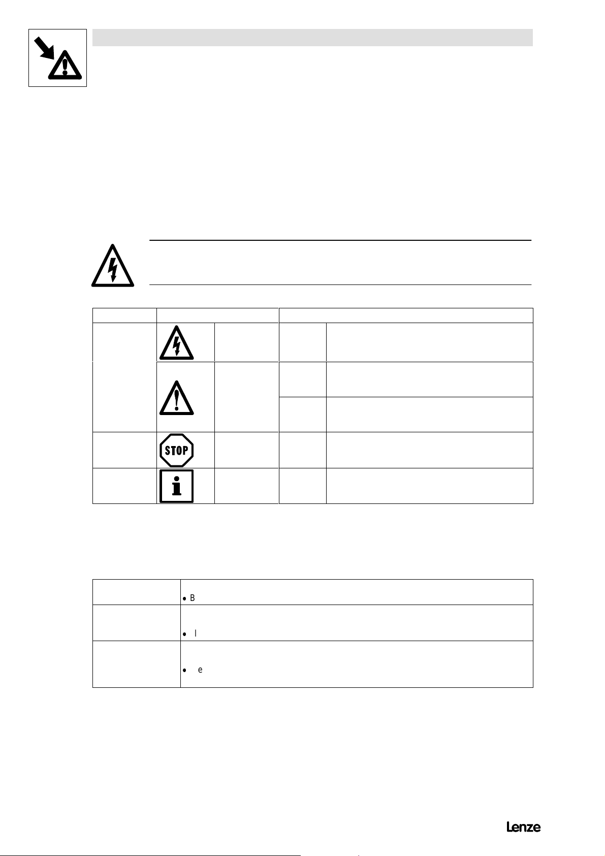
2.2 Layout of the safet y information
- All safety information has a uniform layout:
- The icon characterises the type of danger.
- The signal word characterises the severity of danger.
- The note describes the danger and suggests how to avoid the danger.
Signal word
Note
Icons used Signal words
Warning of
danger to
persons
Warning of
damage to
material
Other notes Note! Designates a general, useful note.
Warning of
hazardous
electr i c alvolt age
Warning of a
general danger
Danger! Warns of impending dangeU .
Consequences if disregarded:
Deat horsevere injur i es.
Warning! Warns of potential,very hazardous situations.
Possible consequences if disregarded:
Deat horsevere injur i es.
Caution! Warns of potential,hazardous situations .
Possible consequences if disregarded:
Light or minor injuries.
Stop! Warns of potential damage to material .
Possible consequences if disregarded:
Dam ageof the contro ller/driv e systemorits enviro n ment
Ifthisnote is obs erved , handlingof the contr o ller/driv e
systemis easier.
.
2.3 Residual hazards
Operator’s safety After mains disconnection, the power terminals U, V, Wand +UG,-UGremainliv efo rat least3 minutes .
Protection of devices Cyclic connection and disconnection of the controller supply voltage at L1, L2, L3 or +UG,+UGmay
Overspeeds Drive systems can reach dangerous overspeeds (e.g. setting high field frequencies for motorsand
8200SHB01992-2
-
Before working onthe controller, check that no voltage is applied to the power terminals.
overload the internal input current limit.
-
Allow at least 3 minutes between disconnection and reconnection.
machines which are not suitable):
-
The controllers do not offer any protection against these operating conditions. Use additional
com po n entsforthis.
Loading...