


EDB82MV752
.5eI
Ä.5eIä
L
Operating Instructions
Global Drive
8200 motec frequency inverter
0.25 kW ... 7.5 kW

This documentation is valid for 8200 motec controllers as of version
E82MV |
xxx |
_ |
x |
B xxx |
XX XX |
3x |
Type
Power
(e.g. 152 = 15 ´ 102 W = 1.5 kW)
(e.g. 113 = 11 ´ 103 W = 11 kW)
Voltage class 2 = 240 V
4 = 400 V/500 V
Device version
Hardware version
Software version
When 8200 motec controllers are operated together with Lenze motors or Lenze geared motors, these instructions are only valid together with the operating instructions for the motors and geared motors.
In the event of service, please state the exact type designation. The function module used can either be identified through the keypad, the PC , or by means of the nameplate stuck on the carrier housing. Moreover, each function module is clearly designated (e.g. STANDARD" for standard I/O).
What is new / what has changed in the Operating Instructions?
Material num- |
Edition |
|
Important |
Contents |
|
ber |
|
|
|
|
|
|
|
|
|
|
|
00402783 |
1.0 |
07/98 |
TD00 |
1. edition |
First edition for pilot series |
|
|
|
|
|
|
00404604 |
2.0 |
11/98 |
TD00 |
2. edition |
Complete revision for series |
|
|
|
|
Replaces |
All chapters: error correction and complete editorial revision |
|
|
|
|
402783 |
|
|
|
|
|
|
|
00422543 |
3.0 |
09/01 |
TD02 |
3. edition |
Extended by frequency inverter 0.25 kW/0.37 kW and 3 kW ... 7.5 kW, |
|
|
|
|
Replaces |
Chapter 3 Technical data": extended by powers 0.25/0.37 kW u. 3..7.5 kW |
|
|
|
|
404604 |
Chapter. 5 Commissioning": extended by step for step commissioning |
|
|
|
|
|
Chapter 12 Accessories": extended and updated |
|
|
|
|
|
All chapters: update, error correction and complete editorial revision |
|
|
|
|
|
|
00459196 |
4.0 |
11/02 |
TD01 |
4. edition |
Change of company name |
|
|
|
|
Replaces |
|
|
|
|
|
422543 |
|
|
|
|
|
|
|
|
4.1 |
02/03 |
TD15 |
Replaces |
Chapter 11 "Braking operation": update |
|
|
|
|
459196 |
|
|
|
|
|
|
|
13206840 |
5.1 |
07/07 |
TD14 |
5. edition |
Extended by device version with electronic switching output K1 |
|
|
|
|
|
Chapter 4.2.1.5, 8, 11.2: update |
|
|
|
|
|
Chapter 4.2.2.5: removed; chapter 4.2.4.4: reference to Communication Manual |
|
|
|
|
|
Chapter 5.4 − 5.5: internal reorganisation |
|
|
|
|
|
Chapter 11.3.2 u 11.3.3: update of brake resistor data |
|
|
|
|
|
Chapter 14: signal flow diagrams (without AIF) updated/newly arranged and code table |
|
|
|
|
|
updated according to SW 3.7 |
|
|
|
|
|
Layout corrections: |
|
|
|
|
|
Chapter 13.1: Table of the application−specific configuration: |
|
|
|
|
|
− Correction of mixed up example values in code 412/1 and 412/5 |
|
|
|
|
|
− Supplement of code 0415 |
|
|
|
|
|
|
E2006 Lenze Drive Systems GmbH
No part of this documentation may be copied or made available without the explicit written approval of Lenze Drive Systems GmbH.
We have compiled all information in this documentation with great care and have checked them with regard to compliance with the hardware and software described. Nevertheless, we cannot entirely exclude deviations. We do not accept legal responsibility or liability for damage possibly resulting therefrom. We will include necessary amendments in the subsequent editions.
Version |
5.2 |
08/2007 |

Contents
1 Preface and general information . |
. . . . . . . . . . . . . . . . . . . . . . . . . . . . . . . . . . . . . . . . . . |
1−1 |
|
1.1 |
The 8200 motec frequency inverter . . |
. . . . . . . . . . . . . . . . . . . . . . . . . . . . . . . . . . . . . . . . . . . . . . . . . . |
1−1 |
1.2 |
About these Operating Instructions ... |
. . . . . . . . . . . . . . . . . . . . . . . . . . . . . . . . . . . . . . . . . . . . . . . . . . |
1−1 |
1.3 |
Terminology used . . . . . . . . . . . . . . . . |
. . . . . . . . . . . . . . . . . . . . . . . . . . . . . . . . . . . . . . . . . . . . . . . . . |
1−1 |
1.4 |
Legal regulations . . . . . . . . . . . . . . . . |
. . . . . . . . . . . . . . . . . . . . . . . . . . . . . . . . . . . . . . . . . . . . . . . . . |
1−2 |
2 Safety information . . . . . . . . . . . . . . . . . . . . . . . . . . . . . . . . . . . . . . . . . . . . . . . . . . . . . . |
2−1 |
|
2.1 |
General safety and application instructions for Lenze controllers . . . . . . . . . . . . . . . . . . . . . . . . . . . . . . |
2−1 |
2.2 |
General safety and application instructions for Lenze motors . . . . . . . . . . . . . . . . . . . . . . . . . . . . . . . . . |
2−3 |
2.3 |
Residual hazards . . . . . . . . . . . . . . . . . . . . . . . . . . . . . . . . . . . . . . . . . . . . . . . . . . . . . . . . . . . . . . . . . |
2−5 |
2.4 |
Layout of the safety information . . . . . . . . . . . . . . . . . . . . . . . . . . . . . . . . . . . . . . . . . . . . . . . . . . . . . . |
2−5 |
3 Technical data . . . . . . . . . . . . . . . . . . . . . . . . . . . . . . . . . . . . . . . . . . . . . . . . . . . . . . . . . |
3−1 |
||
3.1 |
General data/operating conditions . . . . . . . . . . . . . . . . . . . . . . . . . . . . . . . . . . . . . . . . . . . . . . . . . . . . . |
3−1 |
|
3.2 |
Rated data at a mains voltage of 230 V . . . . . . . . . . . . . . . . . . . . . . . . . . . . . . . . . . . . . . . . . . . . . . . . . |
3−5 |
|
|
3.2.1 |
Operation with rated power (normal operation) . . . . . . . . . . . . . . . . . . . . . . . . . . . . . . . . . . . . |
3−5 |
|
3.2.2 |
Operation with increased rated power . . . . . . . . . . . . . . . . . . . . . . . . . . . . . . . . . . . . . . . . . . |
3−6 |
3.3 |
Rated data at a mains voltage of 400/500 V . . . . . . . . . . . . . . . . . . . . . . . . . . . . . . . . . . . . . . . . . . . . . |
3−7 |
|
|
3.3.1 |
Operation with rated power (normal operation) . . . . . . . . . . . . . . . . . . . . . . . . . . . . . . . . . . . . |
3−7 |
|
3.3.2 |
Operation with increased rated power . . . . . . . . . . . . . . . . . . . . . . . . . . . . . . . . . . . . . . . . . . |
3−9 |
4 Installation |
. . . . . . . . |
. . . . . . . . . . . . . . . . . . . . . . . . . . . . . . . . . . . . . . . . . . . . . . . . . . . . |
4−1 |
|
4.1 |
Mechanical installation . . . . . . . . . . . . . . . . . . . . . . . . . . . . . . . . . . . . . . . . . . . . . . . . . . . . . . . . . . . . . |
4−1 |
||
|
4.1.1 |
Important notes . . . . . . . . . . . . . . . . . . . . . . . . . . . . . . . . . . . . . . . . . . . . . . . . . . . . . . . . . . . |
4−1 |
|
|
4.1.2 |
Mechanical design . . . . . . . . . . . . . . . . . . . . . . . . . . . . . . . . . . . . . . . . . . . . . . . . . . . . . . . . |
4−1 |
|
|
4.1.3 |
Dimensions |
. . . . . . . . . . . . . . . . . . . . . . . . . . . . . . . . . . . . . . . . . . . . . . . . . . . . . . . . . . . . . . |
4−2 |
4.2 |
Electrical |
installation . |
. . . . . . . . . . . . . . . . . . . . . . . . . . . . . . . . . . . . . . . . . . . . . . . . . . . . . . . . . . . . . |
4−3 |
|
4.2.1 |
Important notes . . . . . . . . . . . . . . . . . . . . . . . . . . . . . . . . . . . . . . . . . . . . . . . . . . . . . . . . . . . |
4−3 |
|
|
|
4.2.1.1 |
Protection of persons . . . . . . . . . . . . . . . . . . . . . . . . . . . . . . . . . . . . . . . . . . . . . |
4−3 |
|
|
4.2.1.2 |
Motor protection . . . . . . . . . . . . . . . . . . . . . . . . . . . . . . . . . . . . . . . . . . . . . . . . . |
4−3 |
|
|
4.2.1.3 |
Mains types/mains conditions . . . . . . . . . . . . . . . . . . . . . . . . . . . . . . . . . . . . . . . |
4−4 |
|
|
4.2.1.4 |
Operation on public supply systems (compliance with EN 61000−3−2) . . . . . . . . . . |
4−4 |
|
|
4.2.1.5 |
Operation with earth−leakage circuit breaker . . . . . . . . . . . . . . . . . . . . . . . . . . . . |
4−5 |
|
|
4.2.1.6 |
Interaction with compensation equipment . . . . . . . . . . . . . . . . . . . . . . . . . . . . . . |
4−5 |
|
|
4.2.1.7 |
Specification of the cables used . . . . . . . . . . . . . . . . . . . . . . . . . . . . . . . . . . . . . |
4−6 |
|
4.2.2 |
Installation according to EMC . . . . . . . . . . . . . . . . . . . . . . . . . . . . . . . . . . . . . . . . . . . . . . . . . |
4−7 |
|
|
|
4.2.2.1 |
Assembly . . . . . . . . . . . . . . . . . . . . . . . . . . . . . . . . . . . . . . . . . . . . . . . . . . . . . . |
4−7 |
|
|
4.2.2.2 |
Filters . . . . . . . . . . . . . . . . . . . . . . . . . . . . . . . . . . . . . . . . . . . . . . . . . . . . . . . . |
4−7 |
|
|
4.2.2.3 |
Shielding . . . . . . . . . . . . . . . . . . . . . . . . . . . . . . . . . . . . . . . . . . . . . . . . . . . . . . |
4−7 |
|
|
4.2.2.4 |
Earthing . . . . . . . . . . . . . . . . . . . . . . . . . . . . . . . . . . . . . . . . . . . . . . . . . . . . . . . |
4−7 |
|
4.2.3 |
Power connections . . . . . . . . . . . . . . . . . . . . . . . . . . . . . . . . . . . . . . . . . . . . . . . . . . . . . . . . |
4−8 |
|
|
4.2.4 |
Control connections . . . . . . . . . . . . . . . . . . . . . . . . . . . . . . . . . . . . . . . . . . . . . . . . . . . . . . . . |
4−8 |
|
|
|
4.2.4.1 |
Mounting/dismounting the I/O function module . . . . . . . . . . . . . . . . . . . . . . . . . . |
4−8 |
|
|
4.2.4.2 |
Terminal assignment − standard I/O E82ZAFSC001 . . . . . . . . . . . . . . . . . . . . . . . . |
4−9 |
|
|
4.2.4.3 |
Terminal assignment − application I/O E82ZAFAC001 . . . . . . . . . . . . . . . . . . . . . . |
4−12 |
|
|
4.2.4.4 |
Wiring of bus function modules . . . . . . . . . . . . . . . . . . . . . . . . . . . . . . . . . . . . . . |
4−16 |
L
EDB82MV752 EN 5.2 |
i |

Contents
5 Commissioning . . . . . . . . . . . . . . . . . . . . . . . . . . . . . . . . . . . . . . . . . . . . . . . . . . . . . . . . |
5−1 |
||
5.1 |
Before you start . . . . . . . . . . . . . . . . . . . . . . . . . . . . . . . . . . . . . . . . . . . . . . . . . . . . . . . . . . . . . . . . . . |
5−1 |
|
5.2 |
Before switching on . . . . . . . . . . . . . . . . . . . . . . . . . . . . . . . . . . . . . . . . . . . . . . . . . . . . . . . . . . . . . . |
5−1 |
|
|
5.2.1 |
Menu structure . . . . . . . . . . . . . . . . . . . . . . . . . . . . . . . . . . . . . . . . . . . . . . . . . . . . . . . . . . . |
5−2 |
|
5.2.2 |
Changing and saving parameters . . . . . . . . . . . . . . . . . . . . . . . . . . . . . . . . . . . . . . . . . . . . . . |
5−3 |
5.3 |
Selection of the correct control mode . . . . . . . . . . . . . . . . . . . . . . . . . . . . . . . . . . . . . . . . . . . . . . . . . . |
5−4 |
|
5.4 |
Commissioning − V/f characteristic control . . . . . . . . . . . . . . . . . . . . . . . . . . . . . . . . . . . . . . . . . . . . . . |
5−6 |
|
|
5.4.1 |
Commissioning without function module . . . . . . . . . . . . . . . . . . . . . . . . . . . . . . . . . . . . . . . . . |
5−6 |
|
5.4.2 |
Commissioning with standard I/O function module . . . . . . . . . . . . . . . . . . . . . . . . . . . . . . . . . |
5−8 |
5.5 |
Commissioning − vector control . . . . . . . . . . . . . . . . . . . . . . . . . . . . . . . . . . . . . . . . . . . . . . . . . . . . . . |
5−10 |
|
|
5.5.1 |
Commissioning without function module . . . . . . . . . . . . . . . . . . . . . . . . . . . . . . . . . . . . . . . . . |
5−10 |
|
5.5.2 |
Commissioning with standard I/O function module . . . . . . . . . . . . . . . . . . . . . . . . . . . . . . . . . |
5−12 |
|
5.5.3 |
Vector control optimisation . . . . . . . . . . . . . . . . . . . . . . . . . . . . . . . . . . . . . . . . . . . . . . . . . . . |
5−14 |
6 Parameter setting . . . . . . . . . . . . . . . . . . . . . . . . . . . . . . . . . . . . . . . . . . . . . . . . . . . . . . |
6−1 |
|
6.1 |
General information . . . . . . . . . . . . . . . . . . . . . . . . . . . . . . . . . . . . . . . . . . . . . . . . . . . . . . . . . . . . . . . |
6−1 |
6.2 |
Parameter setting via keypad . . . . . . . . . . . . . . . . . . . . . . . . . . . . . . . . . . . . . . . . . . . . . . . . . . . . . . . . |
6−2 |
6.2.1 |
Installation/commissioning . . . . . . . . . . . . . . . . . . . . . . . . . . . . . . . . . . . . . . . . . . . . . . . . . . . |
6−2 |
|
6.2.2 |
Displays and functions . . . . . . . . . . . . . . . . . . . . . . . . . . . . . . . . . . . . . . . . . . . . . . . . . . . . . . |
6−2 |
|
6.2.3 |
Menu structure . . . . . . . . . . . . . . . . . . . . . . . . . . . . . . . . . . . . . . . . . . . . . . . . . . . . . . . . . . . |
6−4 |
|
6.2.4 |
Changing and saving parameters using the keypad . . . . . . . . . . . . . . . . . . . . . . . . . . . . . . . . . |
6−5 |
|
6.2.5 |
Change parameter set . . . . . . . . . . . . . . . . . . . . . . . . . . . . . . . . . . . . . . . . . . . . . . . . . . . . . . |
6−5 |
|
6.2.6 |
Remote parameterisation of system bus nodes . . . . . . . . . . . . . . . . . . . . . . . . . . . . . . . . . . . . |
6−6 |
|
6.2.7 |
Change entries in the user menu . . . . . . . . . . . . . . . . . . . . . . . . . . . . . . . . . . . . . . . . . . . . . . |
6−6 |
|
6.2.8 |
Activation of password protection . . . . . . . . . . . . . . . . . . . . . . . . . . . . . . . . . . . . . . . . . . . . . . |
6−7 |
|
6.3 Parameter setting using the LECOM−A (RS232) communication module . . . . . . . . . . . . . . . . . . . . . . . . . |
6−9 |
||
6.3.1 |
Technical data . . . . . . . . . . . . . . . . . . . . . . . . . . . . . . . . . . . . . . . . . . . . . . . . . . . . . . . . . . . . |
6−9 |
|
|
6.3.1.1 |
General data/operating conditions . . . . . . . . . . . . . . . . . . . . . . . . . . . . . . . . . . . . |
6−9 |
|
6.3.1.2 |
Communication times . . . . . . . . . . . . . . . . . . . . . . . . . . . . . . . . . . . . . . . . . . . . . |
6−10 |
6.3.2 |
Wiring to a host (PC or PLC) . . . . . . . . . . . . . . . . . . . . . . . . . . . . . . . . . . . . . . . . . . . . . . . . . . |
6−11 |
|
|
6.3.2.1 |
Notes on self−made PC system cables . . . . . . . . . . . . . . . . . . . . . . . . . . . . . . . . . |
6−11 |
6.3.3 |
Parameter setting using LECOM−A (RS232) . . . . . . . . . . . . . . . . . . . . . . . . . . . . . . . . . . . . . . . |
6−12 |
|
6.3.4 |
Additional codes for LECOM−A (RS232) . . . . . . . . . . . . . . . . . . . . . . . . . . . . . . . . . . . . . . . . . . |
6−12 |
|
6.3.5 |
Troubleshooting and fault elimination LECOM−A (RS232) . . . . . . . . . . . . . . . . . . . . . . . . . . . . . |
6−16 |
|
7 Function library . . . . . . . . . . . . . . . . . . . . . . . . . . . . . . . . . . . . . . . . . . . . . . . . . . . . . . . . |
7−1 |
||
7.1 |
Operating mode . . . . . . . . . . . . . . . . . . . . . . . . . . . . . . . . . . . . . . . . . . . . . . . . . . . . . . . . . . . . . . . . . |
7−2 |
|
|
7.1.1 |
V/f characteristic control . . . . . . . . . . . . . . . . . . . . . . . . . . . . . . . . . . . . . . . . . . . . . . . . . . . |
7−4 |
|
7.1.2 |
Vector control . . . . . . . . . . . . . . . . . . . . . . . . . . . . . . . . . . . . . . . . . . . . . . . . . . . . . . . . . . . |
7−8 |
|
7.1.3 |
Sensorless torque control with speed limitation . . . . . . . . . . . . . . . . . . . . . . . . . . . . . . . . . . . |
7−10 |
7.2 |
Optimising the operating behaviour . . . . . . . . . . . . . . . . . . . . . . . . . . . . . . . . . . . . . . . . . . . . . . . . . . . |
7−13 |
|
|
7.2.1 |
Slip compensation . . . . . . . . . . . . . . . . . . . . . . . . . . . . . . . . . . . . . . . . . . . . . . . . . . . . . . . . |
7−13 |
|
7.2.2 |
Inverter switching frequency . . . . . . . . . . . . . . . . . . . . . . . . . . . . . . . . . . . . . . . . . . . . . . . . . |
7−14 |
|
7.2.3 |
Oscillation damping . . . . . . . . . . . . . . . . . . . . . . . . . . . . . . . . . . . . . . . . . . . . . . . . . . . . . . . |
7−16 |
|
7.2.4 |
Skip frequencies . . . . . . . . . . . . . . . . . . . . . . . . . . . . . . . . . . . . . . . . . . . . . . . . . . . . . . . . . |
7−17 |
7.3 |
Behaviour in the event of mains switching, mains failure or controller inhibit . . . . . . . . . . . . . . . . . . . . . |
7−18 |
|
ii |
EDB82MV752 EN 5.2 |
L |
Contents
|
7.3.1 |
Start conditions/flying−restart circuit . . . . . . . . . . . . . . . . . . . . . . . . . . . . . . . . . . . . . . . . . . . |
7−18 |
|
7.3.2 |
Controlled deceleration after mains failure/mains disconnection . . . . . . . . . . . . . . . . . . . . . . . |
7−19 |
|
7.3.3 |
Controller inhibit . . . . . . . . . . . . . . . . . . . . . . . . . . . . . . . . . . . . . . . . . . . . . . . . . . . . . . . . . . |
7−20 |
7.4 |
Limit value setting . . . . . . . . . . . . . . . . . . . . . . . . . . . . . . . . . . . . . . . . . . . . . . . . . . . . . . . . . . . . . . . |
7−21 |
|
|
7.4.1 |
Speed range . . . . . . . . . . . . . . . . . . . . . . . . . . . . . . . . . . . . . . . . . . . . . . . . . . . . . . . . . . . . . |
7−21 |
|
7.4.2 |
Current limits . . . . . . . . . . . . . . . . . . . . . . . . . . . . . . . . . . . . . . . . . . . . . . . . . . . . . . . . . . . |
7−23 |
7.5 |
Acceleration, deceleration, braking, stopping . . . . . . . . . . . . . . . . . . . . . . . . . . . . . . . . . . . . . . . . . . . . |
7−24 |
|
|
7.5.1 |
Setting of acceleration times, deceleration times and S−shaped ramps . . . . . . . . . . . . . . . . . . |
7−24 |
|
7.5.2 |
Quick stop . . . . . . . . . . . . . . . . . . . . . . . . . . . . . . . . . . . . . . . . . . . . . . . . . . . . . . . . . . . . . . . |
7−27 |
|
7.5.3 |
Change of direction of rotation . . . . . . . . . . . . . . . . . . . . . . . . . . . . . . . . . . . . . . . . . . . . . . . |
7−28 |
|
7.5.4 |
DC braking (DCB) . . . . . . . . . . . . . . . . . . . . . . . . . . . . . . . . . . . . . . . . . . . . . . . . . . . . . . . . . |
7−30 |
|
7.5.5 |
AC motor braking . . . . . . . . . . . . . . . . . . . . . . . . . . . . . . . . . . . . . . . . . . . . . . . . . . . . . . . . . |
7−31 |
7.6 |
Configuration of analog and digital setpoints and actual values . . . . . . . . . . . . . . . . . . . . . . . . . . . . . . |
7−32 |
|
|
7.6.1 |
Setpoint source selection . . . . . . . . . . . . . . . . . . . . . . . . . . . . . . . . . . . . . . . . . . . . . . . . . . . |
7−32 |
|
7.6.2 |
Analog setpoints via terminal . . . . . . . . . . . . . . . . . . . . . . . . . . . . . . . . . . . . . . . . . . . . . . . . |
7−34 |
|
7.6.3 |
Digital setpoints via frequency input . . . . . . . . . . . . . . . . . . . . . . . . . . . . . . . . . . . . . . . . . . . |
7−39 |
|
7.6.4 |
Setpoints via function "motor potentiometer" . . . . . . . . . . . . . . . . . . . . . . . . . . . . . . . . . . . . . |
7−41 |
|
7.6.5 |
Setpoints via fixed setpoints (JOG) . . . . . . . . . . . . . . . . . . . . . . . . . . . . . . . . . . . . . . . . . . . . |
7−43 |
|
7.6.6 |
Setpoints via keypad . . . . . . . . . . . . . . . . . . . . . . . . . . . . . . . . . . . . . . . . . . . . . . . . . . . . . . |
7−45 |
|
7.6.7 |
Setpoints via a bus system . . . . . . . . . . . . . . . . . . . . . . . . . . . . . . . . . . . . . . . . . . . . . . . . . . |
7−46 |
|
7.6.8 |
Setpoint changeover (hand/remote changeover) . . . . . . . . . . . . . . . . . . . . . . . . . . . . . . . . . . . |
7−47 |
7.7 |
Automatic detection of motor data . . . . . . . . . . . . . . . . . . . . . . . . . . . . . . . . . . . . . . . . . . . . . . . . . . . . |
7−48 |
|
7.8 |
Process controller . . . . . . . . . . . . . . . . . . . . . . . . . . . . . . . . . . . . . . . . . . . . . . . . . . . . . . . . . . . . . . . . |
7−50 |
|
|
7.8.1 |
Setting of control characteristics . . . . . . . . . . . . . . . . . . . . . . . . . . . . . . . . . . . . . . . . . . . . . . |
7−50 |
|
7.8.2 |
Setpoint selection for the process controller . . . . . . . . . . . . . . . . . . . . . . . . . . . . . . . . . . . . . |
7−53 |
|
7.8.3 |
Actual value selection for the process controller . . . . . . . . . . . . . . . . . . . . . . . . . . . . . . . . . . |
7−54 |
|
7.8.4 |
Switching off process controller functions . . . . . . . . . . . . . . . . . . . . . . . . . . . . . . . . . . . . . . . |
7−55 |
7.9 |
Current−limit controller . . . . . . . . . . . . . . . . . . . . . . . . . . . . . . . . . . . . . . . . . . . . . . . . . . . . . . . . . . . . |
7−56 |
|
7.10 |
Free interconnection of analog signals . . . . . . . . . . . . . . . . . . . . . . . . . . . . . . . . . . . . . . . . . . . . . . . |
7−57 |
|
|
7.10.1 |
Free configuration of analog input signals . . . . . . . . . . . . . . . . . . . . . . . . . . . . . . . . . . . . . . . |
7−57 |
|
7.10.2 |
Free configuration of analog outputs . . . . . . . . . . . . . . . . . . . . . . . . . . . . . . . . . . . . . . . . . . . |
7−59 |
|
7.10.3 |
Free configuration of analog process data output words . . . . . . . . . . . . . . . . . . . . . . . . . . . . . |
7−64 |
7.11 |
Free interconnection of digital signals . . . . . . . . . . . . . . . . . . . . . . . . . . . . . . . . . . . . . . . . . . . . . . . . . |
7−68 |
|
|
7.11.1 |
Free configuration of digital input signals . . . . . . . . . . . . . . . . . . . . . . . . . . . . . . . . . . . . . . . . |
7−68 |
|
7.11.2 |
Free configuration of digital outputs . . . . . . . . . . . . . . . . . . . . . . . . . . . . . . . . . . . . . . . . . . . |
7−73 |
|
7.11.3 |
Free configuration of digital process data output words . . . . . . . . . . . . . . . . . . . . . . . . . . . . . |
7−79 |
7.12 |
Thermal motor monitoring . . . . . . . . . . . . . . . . . . . . . . . . . . . . . . . . . . . . . . . . . . . . . . . . . . . . . . . . . . |
7−82 |
|
|
7.12.1 |
I2t monitoring . . . . . . . . . . . . . . . . . . . . . . . . . . . . . . . . . . . . . . . . . . . . . . . . . . . . . . . . . . . . |
7−82 |
|
7.12.2 |
Temperature monitoring of the motor with PTC and earth−fault detection . . . . . . . . . . . . . . . . |
7−84 |
7.13 |
External fault evaluation . . . . . . . . . . . . . . . . . . . . . . . . . . . . . . . . . . . . . . . . . . . . . . . . . . . . . . . . . . . |
7−85 |
|
|
7.13.1 |
External fault detection . . . . . . . . . . . . . . . . . . . . . . . . . . . . . . . . . . . . . . . . . . . . . . . . . . . . . |
7−85 |
|
7.13.2 |
Reset of external faults . . . . . . . . . . . . . . . . . . . . . . . . . . . . . . . . . . . . . . . . . . . . . . . . . . . . . |
7−85 |
7.14 |
Display of operating data, diagnostics . . . . . . . . . . . . . . . . . . . . . . . . . . . . . . . . . . . . . . . . . . . . . . . . . |
7−86 |
|
|
7.14.1 |
Display of operating data . . . . . . . . . . . . . . . . . . . . . . . . . . . . . . . . . . . . . . . . . . . . . . . . . . . |
7−86 |
|
7.14.2 |
Diagnostics . . . . . . . . . . . . . . . . . . . . . . . . . . . . . . . . . . . . . . . . . . . . . . . . . . . . . . . . . . . . . |
7−89 |
L
EDB82MV752 EN 5.2 |
iii |

Contents
|
7.15 |
Parameter set management . . . . . . . . . . . . . . . . . . . . . . . . . . . . . . . . . . . . . . . . . . . . . . . . . . . . . . . . . |
7−91 |
|
|
|
7.15.1 Saving and copying parameter sets . . . . . . . . . . . . . . . . . . . . . . . . . . . . . . . . . . . . . . . . . . . . |
7−91 |
|
|
|
7.15.2 |
Parameter set changeover . . . . . . . . . . . . . . . . . . . . . . . . . . . . . . . . . . . . . . . . . . . . . . . . . . |
7−94 |
|
7.16 |
Individual summary of drive parameters in the user menu . . . . . . . . . . . . . . . . . . . . . . . . . . . . . . . . . . . |
7−95 |
|
8 |
Troubleshooting and fault elimination . . . . . . . . . . . . . . . . . . . . . . . . . . . . . . . . . . . . . . |
8−1 |
||
|
8.1 |
Troubleshooting . . . . . . . . . . . . . . . . . . . . . . . . . . . . . . . . . . . . . . . . . . . . . . . . . . . . . . . . . . . . . . . . . . |
8−1 |
|
|
|
8.1.1 |
Status display (LEDs on the controller) . . . . . . . . . . . . . . . . . . . . . . . . . . . . . . . . . . . . . . . . . . |
8−1 |
|
8.2 |
LEDs on the drive controller (status display) . . . . . . . . . . . . . . . . . . . . . . . . . . . . . . . . . . . . . . . . . . . . . |
8−1 |
|
|
|
8.2.1 |
Error analysis with the history buffer . . . . . . . . . . . . . . . . . . . . . . . . . . . . . . . . . . . . . . . . . . . |
8−1 |
|
8.3 |
Drive performance in case of errors . . . . . . . . . . . . . . . . . . . . . . . . . . . . . . . . . . . . . . . . . . . . . . . . . . . |
8−2 |
|
|
8.4 |
Error elimination . . . . . . . . . . . . . . . . . . . . . . . . . . . . . . . . . . . . . . . . . . . . . . . . . . . . . . . . . . . . . . . . . |
8−3 |
|
|
|
8.4.1 |
Maloperation of the drive . . . . . . . . . . . . . . . . . . . . . . . . . . . . . . . . . . . . . . . . . . . . . . . . . . . |
8−3 |
|
|
8.4.2 |
Fault messages on the keypad or in the parameter setting program Global Drive Control . . . . . |
8−4 |
|
8.5 |
Resetting error messages . . . . . . . . . . . . . . . . . . . . . . . . . . . . . . . . . . . . . . . . . . . . . . . . . . . . . . . . . . |
8−7 |
|
9 |
Automation |
. . . . . . . . . . . . . . . . . . . . . . . . . . . . . . . . . . . . . . . . . . . . . . . . . . . . . . . . . . . |
9−1 |
|
|
9.1 |
System bus function module (CAN) E82ZAFC . . . . . . . . . . . . . . . . . . . . . . . . . . . . . . . . . . . . . . . . . . . . . |
9−1 |
|
10 DC−bus connection . . . . . . . . . . . . . . . . . . . . . . . . . . . . . . . . . . . . . . . . . . . . . . . . . . . . . |
10−1 |
|||
11 |
Braking operation . . . . . . . . . . . . . . . . . . . . . . . . . . . . . . . . . . . . . . . . . . . . . . . . . . . . . . |
11−1 |
||
|
11.1 |
Braking operation without additional measures . . . . . . . . . . . . . . . . . . . . . . . . . . . . . . . . . . . . . . . . . . . |
11−1 |
|
|
11.2 |
Braking operation with external brake resistor . . . . . . . . . . . . . . . . . . . . . . . . . . . . . . . . . . . . . . . . . . . . |
11−1 |
|
|
|
11.2.1 Selection of brake resistors . . . . . . . . . . . . . . . . . . . . . . . . . . . . . . . . . . . . . . . . . . . . . . . . . . |
11−1 |
|
|
|
11.2.2 Rated data of the integrated brake transistor . . . . . . . . . . . . . . . . . . . . . . . . . . . . . . . . . . . . . |
11−2 |
|
|
|
11.2.3 Rated data of Lenze brake resistors . . . . . . . . . . . . . . . . . . . . . . . . . . . . . . . . . . . . . . . . . . . . |
11−3 |
|
12 Accessories |
. . . . . . . . . . . . . . . . . . . . . . . . . . . . . . . . . . . . . . . . . . . . . . . . . . . . . . . . . . . |
12−1 |
||
13 Application examples . . . . . . . . . . . . . . . . . . . . . . . . . . . . . . . . . . . . . . . . . . . . . . . . . . . |
13−1 |
|||
|
13.1 |
Pressure control . . . . . . . . . . . . . . . . . . . . . . . . . . . . . . . . . . . . . . . . . . . . . . . . . . . . . . . . . . . . . . . . . . |
13−1 |
|
|
|
13.1.1 Example 1: Simple pressure control with fixed setpoint selection . . . . . . . . . . . . . . . . . . . . . . . |
13−5 |
|
|
|
13.1.2 Example 2: Simple pressure control with changeable setpoint selection . . . . . . . . . . . . . . . . . . |
13−7 |
|
|
13.2 |
Operation with mid−frequency motors . . . . . . . . . . . . . . . . . . . . . . . . . . . . . . . . . . . . . . . . . . . . . . . . . . |
13−9 |
|
|
13.3 |
Speed control . . . . . . . . . . . . . . . . . . . . . . . . . . . . . . . . . . . . . . . . . . . . . . . . . . . . . . . . . . . . . . . . . . . |
13−10 |
|
|
13.4 |
Group drive (operation with several motors) . . . . . . . . . . . . . . . . . . . . . . . . . . . . . . . . . . . . . . . . . . . . . . |
13−13 |
|
|
13.5 |
Setpoint summation (base and additional load operation) . . . . . . . . . . . . . . . . . . . . . . . . . . . . . . . . . . . . |
13−14 |
|
|
13.6 |
Power control (torque limitation) . . . . . . . . . . . . . . . . . . . . . . . . . . . . . . . . . . . . . . . . . . . . . . . . . . . . . . |
13−15 |
|
14 Appendix . |
. . . . . . . . . . . . . . . . . . . . . . . . . . . . . . . . . . . . . . . . . . . . . . . . . . . . . . . . . . . . |
14−1 |
||
|
14.1 |
Signal flow diagrams . . . . . . . . . . . . . . . . . . . . . . . . . . . . . . . . . . . . . . . . . . . . . . . . . . . . . . . . . . . . |
14−1 |
|
|
14.2 |
Overview of signal processing of standard I/O . . . . . . . . . . . . . . . . . . . . . . . . . . . . . . . . . . . . . . . . . . . . |
14−2 |
|
|
|
14.2.1 Controller with standard I/O . . . . . . . . . . . . . . . . . . . . . . . . . . . . . . . . . . . . . . . . . . . . . . . . . . |
14−2 |
|
iv |
EDB82MV752 EN 5.2 |
L |

Contents
14.3 |
Signal processing in the standard I/O function blocks . |
. . . . . . . . . . . . . . . . . . . . . . . . . . . . . . . . . . . . . |
14−3 |
|
|
14.3.1 Speed setpoint conditioning (NSET1) . . . . . . |
. . . . . . . . . . . . . . . . . . . . . . . . . . . . . . . . . . . . . |
14−3 |
|
|
14.3.2 Process controller and setpoint processing (PCTRL1) . . . . . . . . . . . . . . . . . . . . . . . . . . . . . . . . |
14−4 |
||
|
14.3.3 |
Motor control (MCTRL1) . . . . . . . . . . . . . . . . |
. . . . . . . . . . . . . . . . . . . . . . . . . . . . . . . . . . . . . |
14−5 |
14.4 |
Overview of signal processing of the application I/O . . |
. . . . . . . . . . . . . . . . . . . . . . . . . . . . . . . . . . . . . |
14−6 |
|
|
14.4.1 Controller with application I/O . . . . . . . . . . . |
. . . . . . . . . . . . . . . . . . . . . . . . . . . . . . . . . . . . . |
14−6 |
|
14.5 |
Signal processing in the application I/O function blocks |
. . . . . . . . . . . . . . . . . . . . . . . . . . . . . . . . . . . . . |
14−7 |
|
|
14.5.1 Speed setpoint conditioning (NSET1) . . . . . . |
. . . . . . . . . . . . . . . . . . . . . . . . . . . . . . . . . . . . . |
14−7 |
|
|
14.5.2 Process controller and setpoint processing (PCTRL1) with Application I/O . . . . . . . . . . . . . . . . . |
14−8 |
||
|
14.5.3 Motor control (MCTRL1) with Application I/O . |
. . . . . . . . . . . . . . . . . . . . . . . . . . . . . . . . . . . . . |
14−9 |
|
14.6 |
Code table . . . . . . . . . . . . . . . . . . . . . . . . . . . . . . . . . |
. . . . . . . . . . . . . . . . . . . . . . . . . . . . . . . . . . . . . |
14−10 |
|
14.7 |
Table of attributes . . . . . . . . . . . . . . . . . . . . . . . . . . . |
. . . . . . . . . . . . . . . . . . . . . . . . . . . . . . . . . . . . . |
14−51 |
|
|
14.7.1 |
Standard devices in the power range 0.25 ... |
7.5 kW with standard I/O . . . . . . . . . . . . . . . . . . |
14−52 |
|
14.7.2 |
Standard devices in the power range 0.25 ... |
7.5 kW with application I/O . . . . . . . . . . . . . . . . |
14−56 |
15 Table of keywords . . . . . . . . . . . . . . . . . . . . . . . |
. . . . . . . . . . . . . . . . . . . . . . . . . . . . . . . |
15−1 |
||
L
EDB82MV752 EN 5.2 |
v |

Preface and general information
1Preface and general information
1.1The 8200 motec frequency inverter
Decentralised drive solutions require a flexible combination of motor/geared motor and frequency inverter.
The concept of the 8200 motec frequency inverter is therefore based on a modular system of matching components. Together with a Lenze geared motor or a Lenze three−phase AC motor the 8200 motec is a highly functional electronic variable speed drive.
As compact drives they can be used for adjusting speeds in different application, such as material handling, HVAC technology, automation, etc. A free combination of input and output signals and parallel operation of two interfaces ensure an individual solution for your drive task.
The 8200 motec frequency inverter is directly mounted onto the motor. Wall mounting of the 8200 motec is also possible.
1.2About these Operating Instructions ...
·These Operating Instructions are intended for all persons who install, set−up and adjust the 8200 motec frequency inverter.
·A chapter informs entirely about a subject:
–You therefore only have to read the chapters you are interested in at the moment.
–The Index helps you to find all information about a certain topic.
·These Instructions are meant as addition to the Mounting Instructions which are part of the delivery package:
–The features and funtions are described in detail.
–Examples describe how to set the parameters for typical applications.
–In case of doubt, the Mounting Instructions delivered together with the 8200 motec frequency inverter apply.
·The Mounting Instructions do not inform about the use together with Lenze geared motors and Lenze motors. The most important data are listed on the nameplates. If necessary,
Operating Instructions can always be ordered from Lenze.
1.3Terminology used
Term |
In the following text used for |
|
|
Controller |
Any frequency inverter, servo inverter or DC controller |
|
|
motec |
Frequency inverter 8200 motec |
|
|
Drive |
8200 motec in combination with a geared motor, a three−phase AC motor and other Lenze drive components |
|
|
AIF |
AutomationInterF ace: Interface for a communication module. Accessible from the outside at the heatsink of the motec. |
|
|
FIF |
F unctionInterF ace: Interface for a function module. Is inside the motec. |
|
|
Cxxxx/y |
Subcode y of code Cxxxx (e.g. C0517/3 = subcode 3 of code C0517) |
|
|
Xk/y |
Terminal y on terminal strip Xk (e. g. X3/28 = terminal 28 on terminal strip X3) |
|
|
L
EDB82MV752 EN 5.2 |
1−1 |

Preface and general information
1.4Legal regulations
Labelling |
Nameplate |
|
CE−identification |
Manufacturer |
|
|
|
|
|
|
|
|
Lenze controllers are unambiguously |
|
Conforms to the EC Low Voltage Directive |
Lenze Drive Systems GmbH |
|
|
designated by the contents of the nameplate. |
|
|
Postfach 10 13 52 |
|
|
|
|
|
|
D−31763 Hameln |
|
|
|
|
||
Application as |
8200 motec frequency inverter and accessories |
|
|||
directed |
· must only be operated under the conditions prescribed in these Operating Instructions. |
|
|||
|
· |
are components |
|
|
|
|
|
– for open and closed loop control of variable speed drives with asynchronous standard motors, reluctance motors, PM synchronous |
|||
|
|
motors with asynchronous damping cage. |
|
|
|
|
|
– for installation into a machine |
|
|
|
|
|
– used for assembly together with other components to form a machine. |
|
||
|
· comply with the requirements of the EC Low−Voltage Directive. |
|
|||
|
· are not machines for the purpose of the EC Machinery Directive. |
|
|||
|
· are not to be used as domestic appliances, but only for industrial purposes. |
|
|||
|
Drives with 8200 motec frequency inverters |
|
|
||
|
· meet the EC Electromagnetic Compatibility Directive if they are installed according to the guidelines of CE−typical drive systems. |
||||
|
· |
can be used |
|
|
|
|
|
– for operation on public and non−public mains |
|
||
|
|
– for operation in industrial premises and residential areas. |
|
||
|
· The user is responsible for the compliance of his application with the EC directives. |
|
|||
|
Any other use shall be deemed inappropriate! |
|
|||
|
|
||||
Liability |
· The information, data, and notes in these instructions met the state of the art at the time of printing. Claims referring to drive systems |
||||
|
|
which have already been supplied cannot be derived from the information, illustrations, and descriptions given in these Operating |
|||
|
|
Instructions. |
|
|
|
|
· The specifications, processes, and circuitry described in these instructions are for guidance only and must be adapted to your own specific |
||||
|
|
application. Lenze does not take responsibility for the suitability of the process and circuit proposals. |
|||
|
· The specifications in these Instructions describe the product features without guaranteeing them. |
||||
|
· Lenze does not accept any liability for damage and operating interference caused by: |
|
|||
|
|
– disregarding the operating instructions |
|
|
|
|
|
– unauthorized modifications to the controller |
|
||
|
|
– operating errors |
|
|
|
|
|
– improper working on and with the controller |
|
||
|
|
|
|||
Warranty |
· Warranty conditions: see Sales and Delivery Conditions of Lenze Drive Systems GmbH. |
|
|||
|
· Warranty claims must be made to Lenze immediately after detecting the deficiency or fault. |
|
|||
|
· The warranty is void in all cases where liability claims cannot be made. |
|
|||
|
|
|
|
||
Disposal |
Material |
|
recycle |
dispose |
|
|
|
|
|
|
|
|
Metal |
|
D |
− |
|
|
|
|
|
|
|
|
Plastic |
|
D |
− |
|
|
|
|
|
|
|
|
Assembled PCBs |
|
− |
D |
|
|
|
|
|
|
|
1−2 |
EDB82MV752 EN 5.2 |
L |

Safety instructions
Lenze controllers
2Safety information
2.1General safety and application instructions for Lenze controllers
(According to: Low−Voltage Directive 73/23/EEC)
General
Depending on their degree of protection, some parts of Lenze controllers (frequency inverters, servo inverters, DC controllers) and their accessory components can be live, moving and rotating during operation. Surfaces can be hot.
Non−authorised removal of the required cover, inappropriate use, incorrect installation or operation, creates the risk of severe injury to persons or damage to material assets.
For more information please see the documentation.
All operations concerning transport, installation, and commissioning as well as maintenance must be carried out by qualified, skilled personnel (IEC 364 and CENELEC HD 384 or DIN VDE 0100 and IEC report 664 or DIN VDE 0110 and national regulations for the prevention of accidents must be observed).
According to this basic safety information, qualified, skilled personnel are persons who are familiar with the assembly, installation, commissioning, and operation of the product and who have the qualifications necessary for their occupation.
Application as directed
Drive controllers are components which are designed for installation in electrical systems or machinery. They are not to be used as domestic appliances, but only for industrial purposes according to
EN 61000−3−2.
When installing drive controllers into machines, commissioning of these controllers (i.e. the starting of operation as directed) is prohibited until it is proven that the machine corresponds to the regulations of the EC Directive 98/37/EC (Machinery Directive); EN 60204 must be observed.
Commissioning (i.e. starting of operation as directed) is only allowed when there is compliance with the EMC Directive (89/336/EEC).
The controllers meet the requirements of the Low−Voltage Directive 73/23/EEC. The harmonised standard EN 61800−5−1 applies to the controllers.
The technical data as well as the connection conditions can be obtained from the nameplate and the documentation. They must be strictly observed.
Warning: The controllers are products which can be installed in drive systems of category C2 according to EN 61800−3. These products can cause radio interference in residential areas. In this case, special measures can be necessary.
Transport, storage
Please observe the notes on transport, storage and appropriate handling.
Observe the climatic conditions according to the technical data.
Installation
The controllers must be installed and cooled according to the instructions given in the corresponding documentation.
Ensure proper handling and avoid mechanical stress. Do not bend any components and do not change any insulation distances during transport or handling. Do not touch any electronic components and contacts.
Controllers contain electrostatically sensitive components, which can easily be damaged by inappropriate handling. Do not damage or destroy any electrical components since this might endanger your health!
L
EDB82MV752 EN 5.2 |
2−1 |
Safety instructions
Lenze controllers
Electrical connection
When working on live controllers, the valid national regulations for the prevention of accidents (e.g. VBG 4) must be observed.
Carry out the electrical installation in compliance with the corresponding regulations (e.g. cable cross−sections, fuses, PE connection). More detailed information is given in the corresponding documentation.
Notes about installation according to EMC regulations (shielding, earthing, filters and cable routing) are included in the documentation. These notes also apply to CE−marked controllers. The compliance with limit values required by the EMC legislation is the responsibility of the manufacturer of the machine or system. The controllers must be installed in housings (e.g. control cabinets) to meet the limit values for radio interferences valid at the site of installation. The housings must enable an EMC−compliant installation. Observe in particular that e.g. the control cabinet doors should have a circumferential metal connection to the housing. Reduce housing openings and cutouts to a minimum.
Lenze controllers can cause a DC current in the protective conductor. If a residual current device (RCD) is used as a protective means in the case of direct or indirect contact, only a residual current device (RCD) of type B may be used on the current supply side of the controller. Otherwise, another protective measure, such as separation from the environment through double or reinforced insulation or disconnection from the mains by means of a transformer must be used.
Operation
If necessary, systems including controllers must be equipped with additional monitoring and protection devices according to the valid safety regulations (e.g. law on technical equipment, regulations for the prevention of accidents). The controller can be adapted to your application. Please observe the corresponding information given in the documentation.
After a controller has been disconnected from the voltage supply, all live components and power connections must not be touched immediately because capacitors can still be charged. Please observe the corresponding stickers on the controller.
All protection covers and doors must be shut during operation.
Note for UL approved systems with integrated controllers: UL warnings are notes that only apply to UL systems. The documentation contains special UL notes.
Safety functions
Special controller variants support safety functions (e.g. "safe torque off", formerly "safe standstill") according to the requirements of Annex I No. 1.2.7 of the EC Directive "Machinery" 98/37/EC, EN 954−1
Category 3 and EN 1037. Strictly observe the notes on the safety functions given in the documentation on the respective variants.
Maintenance and servicing
The controllers do not require any maintenance, if the prescribed conditions of operation are observed.
If the ambient air is polluted, the cooling surfaces of the controller may become dirty or the air vents of the controller may be obstructed. Therefore, clean the cooling surfaces and air vents periodically under these operating conditions. Do not use sharp or pointed tools for this purpose!
Waste disposal
Recycle metal and plastic materials. Ensure professional disposal of assembled PCBs.
The product−specific safety and application notes given in these instructions must be observed!
2−2 |
EDB82MV752 EN 5.2 |
L |

Safety instructions
Lenze low−voltage machinery
2.2General safety and application instructions for Lenze motors
(According to: Low−Voltage Directive 73/23/EEC)
General
Low−voltage machines have hazardous live and rotating parts and possibly also hot surfaces.
Synchronous machines induce voltages at open terminals during operation.
All operations concerning transport, connections, commissioning and maintenance must be carried out by qualified, skilled personnel (EN 50110−1 (VDE 0105−100) and IEC 60364 must be observed).
Inappropriate use creates the risk of severe injury to persons and damage to material assets.
Low−voltage machines may only be operated under the conditions that are indicated in the section
"Application as directed".
The conditions at the place of installation must comply with the data given on the nameplate and in the documentation.
Application as directed
Low−voltage machines are intended for commercial installations. They comply with the harmonised standards of the series EN 60034 (VDE 0530). Their use in potentially explosive atmospheres is prohibited unless they are expressly intended for such use (follow additional instructions).
Low−voltage machines are components for installation into machines as defined in the Machinery Directive 98/37/EC. Commissioning is prohibited until the conformity of the end product with this directive has been established (follow i. a. EN 60204−1).
Low−voltage machines with IP23 protection or less are only intended for outdoor use when applying special protective features.
The integrated brakes must not be used as safety brakes. It cannot be ruled out that factors which cannot be influenced, such as oil ingress due to a defective A−side shaft seal, cause a brake torque reduction.
Transport, storage
Damages must be reported immediately upon receipt to the forwarder; if required, commissioning must be excluded. Tighten screwed−in ring bolts before transport. They are designed for the weight of the low−voltage machines, do not apply extra loads. If necessary, use suitable and adequately dimensioned means of transport (e. g. rope guides).
Remove transport locking devices before commissioning. Reuse them for further transport. When storing low−voltage machines, ensure a dry, dust−free and low−vibration (veff £ 0.2 mm/s) environment (bearing damage while being stored).
Installation
Ensure an even surface, solid foot/flange mounting and exact alignment if a direct clutch is connected. Avoid resonances with the rotational frequency and double mains frequency which may be caused by the assembly. Turn rotor by hand, listen for unusual slipping noises. Check the direction of rotation when the clutch is not active (observe section "Electrical connection").
Use appropriate means to mount or remove belt pulleys and clutches (heating) and cover them with a touch guard. Avoid impermissible belt tensions.
The machines are half−key balanced. The clutch must be half−key balanced, too. The visible jutting out part of the key must be removed.
If required, provide pipe connections. Designs with shaft end at bottom must be protected with a cover which prevents the ingress of foreign particles into the fan. Free circulation of the cooling air must be ensured. The exhaust air − also the exhaust air of other machines next to the drive system
− must not be taken in immediately.
L
EDB82MV752 EN 5.2 |
2−3 |

Safety instructions
Lenze low−voltage machinery
Electrical connection
All operations must only be carried out by qualified and skilled personnel on the low−voltage machine at standstill and deenergised and provided with a safe guard to prevent an unintentional restart.This also applies to auxiliary circuits (e. g. brake, encoder, blower).
Check safe isolation from supply!
If the tolerances specified in EN 60034−1; IEC 34 (VDE 0530−1) − voltage ±5 %, frequency ±2 %, waveform, symmetry − are exceeded, more heat will be generated and the electromagnetic compatibility will be affected.
Observe the data on the nameplate, operating notes, and the connection diagram in the terminal box.
The connection must ensure a continuous and safe electrical supply (no loose wire ends); use appropriate cable terminals. The connection to the PE conductor must be safe. The plug−in connectors must be bolt tightly (to stop).
The clearances between blank, live parts and to earth must not fall below 8 mm at Ur £ 550 V, 10 mm at Ur £ 725 V, 14 mm at Ur £ 1000 V.
The terminal box must be free of foreign particles, dirt and moisture. All unused cable entries and the box itself must be sealed against dust and water.
Commissioning and operation
Before commissioning after longer storage periods, measure insulation resistance. In case of values £ 1 kW per volt of rated voltage, dry winding.
For trial run without output elements, lock the featherkey. Do not deactivate the protective devices, not even in a trial run.
Check the correct operation of the brake before commissioning low−voltage machines with brakes.
Integrated thermal detectors do not provide full protection for the machine. If necessary, limit the maximum current. Parameterise the controller so that the motor will be switched off with I > Ir after a few seconds of operation, especially at the risk of blocking.
Vibrational severities veff £ 3.5 mm/s (Pr £ 15 kW) or 4.5 mm/s (Pr > 15 kW) are acceptable if the clutch is activated.
If deviations from normal operation occur, e.g. increased temperatures, noises, vibrations, find the cause and, if required, contact the manufacturer. In case of doubt, switch off the low−voltage machine.
If the machine is exposed to dirt, clean the air paths regularly.
Shaft sealing rings and roller bearings have a limited service life.
Regrease bearings with relubricating devices while the low−voltage machine is running. Only use the grease recommended by the manufacturer. If the grease drain holes are sealed with a plug, (IP54 drive end; IP23 drive and non−drive end), remove plug before commissioning. Seal bore holes with grease. Replace prelubricated bearings (2Z bearing) after approx. 10,000 h − 20,000 h, at the latest however after 3 − 4 years.
The product−specific safety and application notes given in these instructions must be observed!
2−4 EDB82MV752 EN 5.2
L
Safety instructions
Residual hazards, Layout of the safety instructions
2.3Residual hazards
Protection of |
· Deenergise the motec before you start working on it or open the housing. Wait for at least one minute since the power terminals U, V, W; BR0, |
persons |
BR1, BR2 and the pins of the FIF interface remain live after switching off the mains. |
|
– After opening the motec, check if the power terminals L1, L2, L3; U, V, W; BR0, BR1, BR2, the relay outputs K11, K12, K14, and the pins of |
|
the FIF interface are dead. |
|
– Even if the motec is disconnected from the mains, the relay outputs K11, K12, K14 can be live! |
|
· If you do not use the fail−safe function selection of direction of rotation" via the digital signal DCTRL1−CW/CCW (C0007 = −0− ... −13−, C0410/3 |
|
¹ 255): |
|
– In case of open circuit or failure of the control voltage, the drive may change the direction of rotation. |
|
· If you use the "flying restart circuit" function (C0142 = −2−, −3−) for machines with a low moment of inertia and low friction: |
|
– After controller enable has been effected in the standstill status, the motor may temporarily start up, or change direction of rotation. |
|
· The motec heatsink has an operating temperature > 60 °C: |
|
– Skin contact with the heatsink causes burns. |
|
|
Device |
· 8200 motec 3 ... 7.5 kW (E82MV302_4B, E82MV402_4B, E82MV552_4B, E82MV752_4B): |
protection |
Frequent mains switching (e.g. inching mode via mains contactor) may overload and destroy the input current limitation of the controller: |
|
– Thus, at least three minutes have to pass between two switch−on processes. |
|
· Depending on the controller settings, the connected motor can be overheated: |
|
– e. g. long−time operation of the DC injection brake. |
|
– long−time operation of self−ventilated motors at low speeds. |
|
|
Overspeed |
· Drives can attain dangerous overspeeds (e. g. setting of high output frequencies with regard to motors and machines not qualified for this |
|
purpose): |
–The drive controllers do not provide protection against such operating conditions. For this purpose, apply additional components.
2.4Layout of the safety information
All safety information given in these Operating Instructions has the same layout:
Signal word (characterises the severity of danger)
Note (describes the danger and gives information how to avoid it)
|
Icons used |
Signal words |
|
Warning of danger |
Warning of hazardous |
Danger! |
Warns of impending danger. |
to persons |
electrical voltage |
|
Consequences if disregarded: |
|
|
|
Death or most severe injuries |
|
Warning of a general |
Warning! |
Warns of potential, very hazardous situations. |
|
danger |
|
Possible consequences if disregarded: |
|
|
|
Death or most severe injuries |
|
|
Caution! |
Warns of potential, hazardous situations. |
|
|
|
Possible consequences if disregarded: |
|
|
|
Light or minor injuries |
Warning of damage |
|
Stop! |
Warns of potential damage to material. |
to material |
|
|
Possible consequences if disregarded: |
|
|
|
Damage of the controller/drive system or its environment |
More information |
|
Tip! |
Designates a general, useful note. |
|
|
|
If you observe it, handling of the controller/drive system is made easier. |
L
EDB82MV752 EN 5.2 |
2−5 |

Safety instructions
Residual hazards, Layout of the safety instructions
2−6 EDB82MV752 EN 5.2
L

Technical data
General data/operating conditions
3Technical data
3.1General data/operating conditions
Standards and operating conditions
Conformity |
|
|
CE |
Low−Voltage Directive (73/23/EEC) |
|
|
|
|
|
EMC Directive (93/68/EEC) |
|
|
|
|
|
|
|
Approvals |
|
|
UL 508C |
Underwriter Laboratories (File−No. E132659) |
|
|
|
|
|
Power Conversion Equipment |
|
|
|
|
|
|
|
Vibration resistance |
Acceleration resistant up to 2g (Germanischer Lloyd, general conditions) |
||||
|
|
|
|
|
|
Climatic conditions |
|
|
|
||
|
|
|
|
|
|
Storage |
|
|
IEC/EN 60721−3−1 |
1K3 (−25 °C...+60 °C) |
< 6 months |
|
|
|
|
|
|
|
|
|
|
1K3 (−25 °C...+40 °C) |
> 6 months |
|
|
|
|
|
> 2 years: form the DC bus capacitors |
|
|
|
|
|
|
Transport |
|
|
IEC/EN 60721−3−2 |
2K3 (−25 °C...+70 °C) |
|
|
|
|
|
|
|
Operation |
|
|
IEC/EN 60721−3−3 |
3K3 (−20 °C...+60 °C) |
|
|
|
|
|
At temperatures above +40 °C, the rated output current should be derated by |
|
|
|
|
|
2.5 %/ °C |
|
|
|
|
|
|
|
Permissible installation height |
0 ... 4000 m amsl |
|
|
||
|
|
|
The rated output current should be derated by 5 %/1000 m above 1000 m amsl |
||
|
|
|
|
|
|
Degree of pollution |
VDE 0110 part 2 degree of pollution 2 |
|
|||
|
|
|
|
|
|
Mounting positions |
All mounting positions and mounting alignments are permitted |
|
|||
|
|
|
|
|
|
Free space |
|
|
above |
100 mm |
|
|
|
|
|
|
|
|
|
|
to the sides |
100 mm |
|
|
|
|
|
|
|
DC−bus operation |
not possible |
|
|
||
|
|
|
|
|
|
|
|
|
|
|
|
Mechanical design |
|
|
|
||
|
|
|
|
||
Housing |
|
|
Carrier housing: glass−fiber reinforced plastic, heatsink: die−cast aluminium |
||
|
|
|
|
|
|
Screwed |
E82MV251K2B, E82MV371K2B |
|
4 x M20/ 2 x M16 (thread length 10 mm, without counternut) |
|
|
connections |
|
|
|
|
|
E82MV551K4B, E82MV751K4B |
|
2 x M25/ 4 x M16 (thread length 10 mm, without counternut) |
|
||
|
|
|
1 x M20 for motor cable in case of wall mounting (EMC cable gland, thread length 10 mm, with counternut) |
||
|
|
|
|
||
|
E82MV152K4B, E82MV222K4B |
|
2 x M25/1 x M20/4 x M16 (thread length 10 mm, without counternut) |
||
|
|
|
1 x M20 for motor cable in case of wall mounting (EMC cable gland, thread length 10 mm, with counternut) |
||
|
|
|
|
|
|
|
E82MV302K4B, E82MV402K4B, |
|
3 x M25/4 x M16 (thread length 10 mm, without counternut) |
|
|
|
E82MV552K4B, E82MV752K4B |
|
|
|
|
|
|
|
|
|
|
L
EDB82MV752 EN 5.2 |
3−1 |

Technical data
General data/operating conditions
General electrical data
EMC |
Complies with requirements according to EN 61800−3/A11 |
|
|
|
|
|
|
Noise emission |
Motor mounting |
Complies with the limit classes A and B (for B: at a max. switching |
|
|
|
frequency of 8 kHz ) acc. to EN 61800−3 |
|
|
|
|
|
|
Wall mounting |
Complies with the limit class A acc. to EN 61800−3 |
|
|
|
(up to 10 m shielded motor cable) |
|
|
|
Complies with the limit class B acc. to EN 61800−3 |
|
|
|
(up to 1 m shielded motor cable; at a max. switching frequency of |
|
|
|
8 kHz) |
|
|
|
|
|
Noise immunity |
Requirements |
Standard |
Severities |
|
|
|
|
|
ESD |
EN 61000−4−2 |
3, i. e. 8 kV with air discharge, |
|
|
|
6 kV with contact discharge |
|
|
|
|
|
Cable−guided high frequency |
EN 61000−4−6 |
150 kHz ... 80 MHz, 10 V/m 80 % AM (1kHz) |
|
|
|
|
|
RF interference (housing) |
EN 61000−4−3 |
80 MHz ... 1000 MHz, 10 V/m 80 % AM (1kHz) |
|
|
|
|
|
Burst |
EN 61000−4−4 |
3/4, i. e. 2 kV/5 kHz |
|
|
|
|
|
Surge |
EN 61000−4−5 |
3, i. e. 1.2/50 ms, |
|
(Surge voltage on mains cable) |
|
1 kV phase−phase, 2 kV phase−PE |
|
|
|
|
Insulation resistance |
Overvoltage category III acc. to EN 61800−5−1 |
|
|
|
|
|
|
Discharge current to PE (to EN 61800−5−1) |
> 3.5 mA |
Observe regulations and safety instructions! |
|
|
|
|
|
Enclosure |
IP54 (NEMA 250 type 12) |
when using the fan module |
|
|
|
|
|
|
IP55 (NEMA 250 type 12) |
without fan module and without protective cap on the AIF interface |
|
|
|
|
|
|
IP65 (NEMA 250 type 4) |
without fan module and with protective cap on the AIF interface |
|
|
|
||
Protective measures against |
Short circuit, earth fault, overvoltage, motor stalling, motor overtemperature (input for PTC or thermal contact, |
||
|
I2t monitoring) |
|
|
Protective insulation of control circuits |
Safe mains isolation: |
|
|
|
Double/reinforced insulation to EN 61800−5−1 |
|
|
|
|
|
|
3−2 |
EDB82MV752 EN 5.2 |
L |

Technical data
General data/operating conditions
Open and closed loop control
Open and closed−loop control methods |
V/f characteristic control (linear, quadratic), vector control, torque selection |
|
|
|||
Switching frequency |
|
optionally 2 kHz, 4 kHz, 8 kHz, 16 kHz |
|
|
|
|
Torque behaviour |
Maximum torque |
1.8 x MN for 60 s |
if rated motor power = rated controller power |
|
|
|
|
Setting range |
1 : 10 |
in speed setting range 3 ... 50 Hz, accuracy < 8 % |
|
|
|
|
Torque/speed |
|
|
|
|
|
|
characteristic |
M/MN |
|
|
|
|
|
|
2.0 |
|
|
|
|
|
|
1.8 |
|
|
|
|
|
|
1.0 |
|
|
|
|
|
|
|
500 |
1000 |
1500 |
n [min-1] |
Sensorless speed |
Minimum output |
1.0 Hz (0 ... MN) |
|
|
|
|
control |
frequency |
|
|
|
|
|
|
Setting range |
1 : 50 |
related to 50 Hz and MN |
|
|
|
|
Accuracy |
± 0.5 % |
in speed setting range 3 ... 50 Hz |
|
|
|
|
Smooth running |
± 0.1 Hz |
|
|
||
|
|
|
|
|
||
Output frequency |
Range |
− 650 Hz ... + 650 Hz |
|
|
|
|
|
Absolute resolution |
0.02 Hz |
|
|
|
|
|
Standardised |
Parameter data: 0.01 %, process data: 0.006 % (= 214) |
|
|
|
|
|
resolution |
|
|
|
|
|
Digital setpoint |
Accuracy |
± 0.005 Hz (= ±100 ppm) |
|
|
|
|
selection |
|
|
|
|
|
|
Analog setpoint |
Linearity |
± 0.5 % |
Signal level: 5 V or 10 V |
|
|
|
selection |
Temperature |
+ 0.3 % |
0 ... 60 °C |
|
|
|
|
sensitivity |
|
|
|
|
|
|
Offset |
± 0 % |
|
|
|
|
L
EDB82MV752 EN 5.2 |
3−3 |

Technical data
General data/operating conditions
Inputs and outputs
Analog |
with standard I/O |
1 input, optionally bipolar |
|
inputs/outputs |
|
1 output |
|
|
|
|
|
|
|
with application I/O |
2 inputs, optionally bipolar |
|
|
|
2 outputs |
|
|
|
|
Digital |
with standard I/O |
4 inputs, optionally 1 frequency input, single−track 0 ... 10 kHz / two−track 0...1 kHz; 1 input for controller inhibit |
|
inputs/outputs |
|
1 output |
|
|
|
|
|
|
|
with application I/O |
6 inputs, optionally 1 frequency input, single−track / two−track 0 ... 102.4 kHz; 1 input for controller inhibit |
|
|
|
2 outputs, 1 frequency output 50 Hz ... 10 kHz |
|
|
|
|
Cycle times |
digital inputs |
1 ms |
|
|
|
|
|
|
|
digital outputs |
4 ms |
|
|
|
|
|
|
analog inputs |
2 ms |
|
|
|
|
|
|
analog outputs |
4 ms (smoothing time: t = 10 ms) |
|
|
||
Relay output (device version 151) |
Changeover contact, AC 250 V/3 A, DC 24 V/2 A ... 240 V/0.22 A |
||
|
|
||
digital switching output |
DC 24 V ext./50 mA or DC 20 V int./10 mA |
||
(device versions 152 and 153) |
|
||
|
|
||
Operation in generator mode |
Integrated brake transistor |
||
(monitored internally) |
|
external brake resistors: (^ 11−1 ) |
|
|
|
|
|
3−4 |
EDB82MV752 EN 5.2 |
L |

Technical data
Rated data at 230 V mains voltage
3.2Rated data at a mains voltage of 230 V
3.2.1Operation with rated power (normal operation)
Typical motor power |
|
|
PN [kW] |
0.25 |
|
0.37 |
Three−phase asynchronous motor |
|
|
|
|
|
|
|
PN [hp] |
0.34 |
|
0.5 |
||
(4−pole) |
|
|
|
|||
|
|
|
|
|
|
|
8200 motec |
|
|
Type |
E82MV251_2B |
|
E82MV371_2B |
|
|
|
|
|
|
|
Mains voltage |
|
|
Umains [V] |
1/N/PE AC 180 V − 0 % ... 264 V + 0 % ; |
45 Hz − 0 % ... 65 Hz + 0 % |
|
Data for operation at 1/N/PE AC 230 V |
|
|
|
|
||
|
|
|
|
|
|
|
Rated mains current |
|
|
Imains [A] |
3.4 |
|
5.0 |
Rated output current at |
2 kHz |
|
IN24 [A] 2) |
2.0 |
|
2.9 |
switching frequency |
|
|
|
|||
4 kHz |
|
|
||||
|
|
|
|
|
|
|
|
|
|
|
|
|
|
|
8 kHz |
|
IN8 [A] |
1.7 |
|
2.4 |
|
16 kHz |
|
IN16 [A] |
1.1 |
|
1.6 |
Max. permissible output |
2 kHz |
|
Imax24 [A] |
2.5 |
|
3.6 |
current for 60 s at |
|
|
|
|||
4 kHz |
|
|
||||
switching frequency 1) |
|
|
|
|
|
|
|
|
|
|
|
|
|
8 kHz |
|
Imax8 [A] |
2.5 |
|
3.6 |
|
|
|
|
||||
|
16 kHz |
|
Imax16 [A] |
1.6 |
|
1.4 |
Output voltage |
|
|
UM [V] |
3~ 0 ... Umains / 0 ... 650 Hz |
||
Power loss (operation with IN8) |
|
Pv [W] |
30 |
|
40 |
|
Dimensions |
|
|
L x W x H [mm] |
190 x 138 x 100 |
||
|
|
|
|
|
|
|
Weight |
|
|
m [kg] |
1.8 |
|
1.8 |
|
|
|
|
|
|
|
Bold print = data for operation at a switching frequency of 8 kHz (Lenze setting)
1)Currents for periodic load change: 1 min overcurrent time with Imax and 2 min base load time with 75 % INx
2)Under different operating conditions possible for some types: Operation with increased rated output current with the same load change cycle (^3−6)
Fuses and cable cross−sections
8200 motec |
|
|
|
|
|
Normal operation |
|
|
|
|
|
|
|
|
|
|
|
|
|
|
|
|
|
Installation acc. to EN 60204−1 |
Installation acc. to UL 1) |
|
|||
Type |
|
System |
Fuse |
|
Circuit breaker |
L1, L2, L3, PE |
Fuse |
L1, L2, L3, PE |
FI |
|
[kW] |
|
|
|
|
[mm2] |
|
[AWG] |
|
|
|
|
|
|
|
|
|||
E82MV251_2B |
0.25 |
1/N/PE AC |
M10 A |
|
C10 A |
1.5 |
10 A |
16 |
³ 30 mA 2) |
|
|
180 ... 264 V; |
|
|
|
|
|
|
|
E82MV371_2B |
0.37 |
M10 A |
|
C10 A |
1.5 |
10 A |
16 |
||
45 ... 65 Hz |
|
|
|||||||
|
|
|
|
|
|
|
|
|
|
1)Only use UL−approved cables, fuses, and fuse holders.
UL fuse: voltage 240 V, tripping characteristic "H", "K5" or "CC"
2)Pulse current sensitive or universal−current sensitive earth−leakage circuit breaker Observe national and regional regulations
L
EDB82MV752 EN 5.2 |
3−5 |
Technical data
Rated data at 230 V mains voltage
3.2.2Operation with increased rated power
Under the application conditions described here the controller can be operated in continuous operation with a motor of higher performance. The overload capacity is reduced to 120 %.
·Typical applications:
–Pumps with quadratic load characteristic
–Fan
·Operation is only permissible
–in the mains voltage ranges mentioned
–at a switching frequency of 2 or 4 kHz
–with the prescribed fuses and cable cross−sections
Typical motor power |
|
|
PN [kW] |
0.37 |
|
0.55 |
Three−phase asynchronous motor |
|
|
|
|
|
|
|
PN [hp] |
0.5 |
|
0.75 |
||
(4−pole) |
|
|
|
|||
|
|
|
|
|
|
|
8200 motec |
|
|
Type |
E82MV251_2B |
|
E82MV371_2B |
|
|
|
|
|
|
|
Mains voltage |
|
|
Umains [V] |
1/N/PE AC 180 V − 0 % ... 264 V + 0 % ; |
45 Hz − 0 % ... 65 Hz + 0 % |
|
Data for operation on 1/N/PE AC 230 V |
|
|
|
|
||
|
|
|
|
|
|
|
Rated mains current |
|
|
Imains [A] |
4.1 |
|
6.0 |
Rated output current at |
2 kHz |
|
IN24 [A] |
2.0 |
|
2.9 |
switching frequency |
|
|
|
|||
4 kHz |
|
|
||||
|
|
|
|
|
|
|
|
|
|
|
|
|
|
Max. permissible output |
2 kHz |
|
|
|
|
|
current for 60 s at |
|
|
Imax24 [A] |
2.5 |
|
3.6 |
4 kHz |
|
|
||||
switching frequency 1) |
|
|
|
|
|
|
Output voltage |
|
|
UM [V] |
3~ 0 ... Umains / 0 ... 650 Hz |
||
Power loss (operation with IN24) |
|
Pv [W] |
30 |
|
40 |
|
Dimensions |
|
|
L x W x H [mm] |
190 x 138 x 100 |
||
|
|
|
|
|
|
|
Weight |
|
|
m [kg] |
1.8 |
|
1.8 |
|
|
|
|
|
|
|
1)Currents for periodic load change with 1 min overcurrent time with Imax and 2 min base load time with 75 % INx
Fuses and cable cross−sections
8200 motec |
|
|
|
|
Operation with increased rated power |
|
|
|
||
|
|
|
|
|
|
|
|
|
|
|
|
|
|
|
Installation acc. to EN 60204−1 |
Installation acc. to UL 1) |
|
||||
Type |
|
System |
Fuse |
|
Circuit breaker |
L1, L2, L3, PE |
Fuse |
L1, L2, L3, PE |
FI |
|
|
[kW] |
|
|
|
|
[mm2] |
|
|
[AWG] |
|
|
|
|
|
|
|
|
|
|||
E82MV251_2B |
0.37 |
1/N/PE AC |
M10 A |
|
C10 A |
1.5 |
10 |
A |
16 |
³ 30 mA 2) |
|
|
180 ... 264 V; |
|
|
|
|
|
|
|
|
E82MV371_2B |
0.55 |
M10 A |
|
C10 A |
1.5 |
10 |
A |
16 |
||
45 ... 65 Hz |
|
|
||||||||
|
|
|
|
|
|
|
|
|
|
|
1)Only use UL−approved cables, fuses, and fuse holders.
UL fuse: voltage 240 V, tripping characteristic "H", "K5" or "CC"
2)Pulse current sensitive or universal−current sensitive earth−leakage circuit breaker Observe national and regional regulations
3−6 EDB82MV752 EN 5.2
L

Technical data
Rated data at 400/500 V mains voltage
3.3Rated data at a mains voltage of 400/500 V
3.3.1Operation with rated power (normal operation)
Typical motor power |
|
PN [kW] |
|
0.55 |
|
0.75 |
|
1.5 |
|
|
2.2 |
||||
Three−phase asynchronous motor |
|
|
|
|
|
|
|
|
|
|
|
|
|
|
|
PN [hp] |
|
0.75 |
|
1.0 |
|
2.0 |
|
|
3.0 |
||||||
(4−pole) |
|
|
|
|
|
|
|||||||||
|
|
|
|
|
|
|
|
|
|
|
|
||||
8200 motec |
|
Type |
E82MV551_4B |
E82MV751_4B |
|
E82MV152_4B |
E82MV222_4B |
||||||||
|
|
|
|
|
|
|
|
|
|
|
|
|
|
||
Mains voltage |
|
Umains [V] |
|
|
3/PE AC 320 V − 0 % ... 550 V + 0 % ; |
45 Hz − 0 % ... 65Hz + 0 % |
|
|
|||||||
Data for operation on 3/PE AC |
|
400 V |
|
500 V |
400 V |
|
500 V |
400 V |
|
500 V |
400 V |
|
500 V |
||
|
|
|
|
|
|
|
|
|
|
|
|
|
|
|
|
Rated mains current |
|
Imains [A] |
1.8 |
|
1.4 |
2.4 |
|
1.9 |
|
3.8 |
|
3.0 |
5.5 |
|
4.5 |
Rated output current at |
2 kHz |
IN24 [A] 2) |
2.1 |
|
1.8 |
2.9 |
|
2.4 |
|
4.6 |
|
3.9 |
6.7 |
|
5.6 |
switching frequency |
|
|
|
|
|
|
|||||||||
4 kHz |
|
|
|
|
|
||||||||||
|
|
|
|
|
|
|
|
|
|
|
|
|
|
|
|
|
|
|
|
|
|
|
|
|
|
|
|
|
|
|
|
|
8 kHz |
IN8 [A] |
1.8 |
|
1.6 |
2.4 |
|
2.1 |
|
3.9 |
|
3.5 |
5.6 |
|
5.0 |
|
16 kHz |
IN16 [A] |
1.2 |
|
1.1 |
1.6 |
|
1.4 |
|
2.5 |
|
2.3 |
3.6 |
|
3.2 |
Max. permissible output |
2 kHz |
Imax24 [A] |
2.7 |
|
2.4 |
3.6 |
|
3.2 |
|
5.8 |
|
5.2 |
8.4 |
|
7.6 |
current for 60 s at |
|
|
|
|
|
|
|||||||||
4 kHz |
|
|
|
|
|
||||||||||
switching frequency 1) |
|
|
|
|
|
|
|
|
|
|
|
|
|
|
|
|
|
|
|
|
|
|
|
|
|
|
|
|
|
|
|
8 kHz |
Imax8 [A] |
2.7 |
|
2.4 |
3.6 |
|
3.2 |
|
5.8 |
|
5.2 |
8.4 |
|
7.6 |
|
|
|
|
|
|
|
||||||||||
|
16 kHz |
Imax16 [A] |
1.8 |
|
1.6 |
2.4 |
|
2.1 |
|
3.9 |
|
3.5 |
5.3 |
|
4.8 |
Output voltage |
|
UM [V] |
|
|
|
|
3~ 0 ... Umains / 0 ... 650 Hz |
|
|
|
|
||||
Power loss (operation with IN8) |
Pv [W] |
|
35 |
|
45 |
|
70 |
|
|
95 |
|||||
Dimensions |
|
L x W x H [mm] |
|
|
202 x 156 x 151 |
|
|
|
|
|
230 x 176 x 167 |
|
|
||
|
|
|
|
|
|
|
|
|
|
|
|
||||
Weight |
|
m [kg] |
|
2.8 |
|
2.8 |
|
4.1 |
|
|
4.1 |
||||
|
|
|
|
|
|
|
|
|
|
|
|
|
|
|
|
|
|
|
|
|
|
|
|
|
|
|
|
||||
Typical motor power |
|
PN [kW] |
|
3.0 |
|
4.0 |
|
5.5 |
|
|
7.5 |
||||
Three−phase asynchronous motor |
|
|
|
|
|
|
|
|
|
|
|
|
|
|
|
PN [hp] |
|
4.1 |
|
5.4 |
|
7.5 |
|
|
10.2 |
||||||
(4−pole) |
|
|
|
|
|
|
|||||||||
|
|
|
|
|
|
|
|
||||||||
8200 motec |
|
Type |
E82MV302_4B |
E82MV402_4B |
|
E82MV552_4B |
E82MV752_4B |
||||||||
|
|
|
|
|
|
|
|
|
|
|
|
||||
Mains voltage |
|
Umains [V] |
|
|
3/PE AC 320 V − 0 % ... 550 V + 0 % ; |
45 Hz − 0 % ... 65Hz + 0 % |
|
|
|||||||
Data for operation on 3/PE AC |
|
400 V |
|
500 V |
400 V |
|
500 V |
400 V |
|
500 V |
400 V |
|
500 V |
||
|
|
|
|
|
|
|
|
|
|
|
|
|
|
|
|
Rated mains current |
|
Imains [A] |
9.5 |
|
7.6 |
12.3 |
|
9.8 |
16.8 |
|
13.4 |
21.5 |
|
17.2 |
|
Rated output current at |
2 kHz |
IN24 [A] 2) |
8.8 |
|
7.0 |
11.4 |
|
9.2 |
15.6 |
|
12.5 |
16.5 |
|
13.2 |
|
switching frequency |
|
|
|
|
|
||||||||||
4 kHz |
|
|
|
|
|||||||||||
|
|
|
|
|
|
|
|
|
|
|
|
|
|
|
|
|
8 kHz |
IN8 [A] |
7.3 |
|
5.8 |
9.5 |
|
7.6 |
13.0 |
|
10.4 |
16.5 |
|
13.2 |
|
|
16 kHz |
IN16 [A] |
4.7 |
|
4.2 |
6.1 |
|
5.5 |
8.4 |
|
7.6 |
10.7 |
|
9.6 |
|
Max. permissible output |
2 kHz |
Imax24 [A] |
11.0 |
|
8.7 |
14.2 |
|
11.4 |
19.5 |
|
15.6 |
24.8 |
|
19.8 |
|
current for 60 s at |
|
|
|
|
|
||||||||||
4 kHz |
|
|
|
|
|||||||||||
switching frequency 1) |
|
|
|
|
|
|
|
|
|
|
|
|
|
|
|
|
|
|
|
|
|
|
|
|
|
|
|
|
|
|
|
8 kHz |
Imax8 [A] |
11.0 |
|
8.7 |
14.2 |
|
11.4 |
19.5 |
|
15.6 |
24.8 |
|
19.8 |
||
|
|
|
|
|
|||||||||||
|
16 kHz |
Imax16 [A] |
7.1 |
|
6.4 |
9.1 |
|
8.2 |
12.7 |
|
11.4 |
16.1 |
|
14.5 |
|
Output voltage |
|
UM [V] |
|
|
|
|
3~ 0 ... Umains / 0 ... 650 Hz |
|
|
|
|
||||
Power loss (operation with IN8) |
Pv [W] |
|
14o |
|
180 |
|
230 |
|
|
290 |
|||||
Dimensions |
|
L x W x H [mm] |
|
|
|
325 x 211 x 163 (223**) |
|
|
|
|
|
|
|
||
|
|
|
|
|
|
|
|
|
|
|
|
||||
Weight |
|
m [kg] |
|
9.7 |
|
9.7 |
|
9.7 |
|
|
9.7 |
||||
|
|
|
|
|
|
|
|
|
|
|
|
|
|
|
|
Bold print = data for operation at a switching frequency of 8 kHz (Lenze setting)
1)Currents for periodic load change: 1 min overcurrent time with Imax and 2 min base load time with 75 % INx
2)Under different operating conditions possible for some types: Operation with increases rated output current with the same load change cycle (^3−9)
**for wall mounting or with a supplementary module (E82ZMV)
L
EDB82MV752 EN 5.2 |
3−7 |
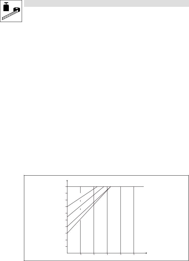
Technical data
Rated data at 400/500 V mains voltage
Fuses and cable cross−sections
8200 motec |
|
|
|
|
|
Normal operation |
|
|
|
|
|
|
|
|
|
|
|
|
|
|
|
|
|
Installation acc. to EN 60204−1 |
Installation acc. to UL 1) |
|
|||
Type |
|
System |
Fuse |
|
Circuit breaker |
L1, L2, L3, PE |
Fuse |
L1, L2, L3, PE |
FI |
|
[kW] |
|
|
|
|
[mm2] |
|
[AWG] |
|
|
|
|
|
|
|
|
|||
E82MV551_4B |
0.55 |
|
M6 A |
|
B6 A |
1 |
5 A |
18 |
|
|
|
|
|
|
|
|
|
|
|
E82MV751_4B |
0.75 |
|
M6 A |
|
B6 A |
1 |
5 A |
18 |
³ 30 mA 2) |
|
|
|
|
|
|
|
|
|
|
E82MV152_4B |
1.5 |
3/PE AC |
M6 A |
|
B6 A |
1 |
5 A |
18 |
|
|
|
||||||||
|
|
|
|
|
|
|
|
|
|
E82MV222_4B |
2.2 |
M10 A |
|
B10 A |
1.5 |
10 A |
16 |
|
|
320 ... 550 V; |
|
|
|||||||
|
|
|
|
|
|
|
|
|
|
E82MV302_4B |
3.0 |
M16 A |
|
B16 A |
2.5 |
15 A |
14 |
|
|
45 ... 65 Hz |
|
|
|||||||
|
|
|
|
|
|
|
|
|
|
E82MV402_4B |
4.0 |
M20 A |
|
B20 A |
4.0 |
20 A |
12 |
³ 300 mA 2) |
|
|
|
||||||||
|
|
|
|
|
|
|
|
|
|
E82MV552_4B |
5.5 |
|
M25 A |
|
B25 A |
4.0 |
25 A |
10 |
|
|
|
|
|||||||
|
|
|
|
|
|
|
|
|
|
E82MV752_4B |
7.5 |
|
M32 A |
|
B32 A |
6.0 |
35 A |
8 |
|
|
|
|
|
|
|
|
|
|
|
1)Only use UL−approved cables, fuses, and fuse holders.
UL fuse: voltage 500 ... 600 V, tripping characteristic "H", "K5" or "CC"
2)Universal−current sensitive earth−leakage circuit breaker
Observe national and regional regulations
Current derating
Depending on the operating conditions and the use of the 8200 motec, the types E82MV302_4B to EMV752_4B may require a reduction of the rated output current in continuous operation:
8200 motec mounted on... |
Current derating |
|
|
...Lenze motor/forced ventilated geared motor |
not required |
|
|
...Lenze motor/self−ventilated geared motor |
see illustration below |
|
|
...Lenze motor/self−ventilated geared motor with E82ZMV supplementary module |
not required |
|
|
...no Lenze motor/geared motor Þ E82ZMV supplementary module is always required |
not required |
|
|
...the wall (wall mounting) Þ E82ZMV supplementary module is always required |
not required |
|
|
I/IN |
|
|
|
|
|
|
|
|
|
|
|
|
|
|
|
|
|
|
|
|
1 |
|
|
|
|
|
|
|
|
|
|
|
|
|
|
|
|
|
|
|
|
0,9 |
|
|
|
|
|
|
|
|
|
|
|
|
|
|
|
|
|
|
|
|
|
|
|
|
|
|
|
|
|
|
|
|
|
|
|
B |
|
|
|
|
|
|
|
|
|
|
|
|
|
|
|
|
|
|
|
4 |
|
|
|
|
|
|
|
|
|
|
|
|
|
|
|
|
|
|
_ |
|
|
|
|
|
|||
|
|
|
|
|
|
|
|
|
|
2 |
|
|
|
|
|
|
||||
|
|
|
|
|
|
|
|
0 |
|
|
|
|
|
|
|
|
|
|||
0,8 |
|
|
|
|
|
|
3 |
|
|
|
|
|
|
|
|
|
|
|
||
|
|
|
|
|
V |
|
|
|
|
|
|
|
|
|
|
|
|
|||
|
|
|
|
|
M |
|
|
|
|
|
|
|
|
|
|
|
|
|
|
|
|
|
|
2 |
|
|
|
|
|
|
|
|
|
|
|
|
|
|
|
||
|
8 |
|
|
|
|
|
|
|
|
|
|
|
|
|
|
|
|
|||
|
E |
|
|
|
|
|
|
|
|
|
|
|
|
B |
|
|
|
|
|
|
|
|
|
|
|
|
|
|
|
|
|
|
|
|
|
|
|
|
|
|
|
|
|
|
|
|
|
|
|
|
|
|
|
|
4 |
|
|
|
|
|
||
0,7 |
|
|
|
|
|
|
|
|
|
|
_ |
|
|
|
|
|
|
|||
|
|
|
|
|
|
|
|
2 |
|
|
|
|
|
|
|
|
||||
|
|
|
|
|
|
|
|
0 |
|
|
|
|
|
|
|
|
|
|
||
|
|
|
|
|
|
|
4 |
|
|
|
|
|
|
|
|
|
|
|
|
|
|
|
|
|
|
|
V |
|
|
|
|
|
|
|
|
|
|
|
|
|
|
|
|
|
|
|
M |
|
|
|
|
|
|
|
|
|
|
|
|
|
|
|
|
|
|
2 |
|
|
|
|
|
|
|
|
|
|
|
|
|
|
|
||
0,6 |
8 |
|
|
|
|
|
|
|
|
|
|
B |
|
|
|
|
|
|||
E |
|
|
|
|
|
|
|
|
|
|
|
|
|
|
|
|
|
|||
|
|
|
|
|
|
|
|
|
|
|
|
|
4 |
|
|
|
|
|
||
|
|
|
|
|
|
|
|
|
|
|
_ |
|
|
|
|
|
|
|
||
|
|
|
|
|
|
|
|
|
2 |
|
|
|
|
|
|
|
|
|
||
|
|
|
|
|
|
|
|
5 |
|
|
|
|
|
|
|
|
|
|
|
|
|
|
|
|
|
|
|
5 |
|
|
|
|
|
B |
|
|
|
|
|
||
|
|
|
|
|
|
V |
|
|
|
|
4 |
|
|
|
|
|
||||
0,5 |
|
|
|
|
M |
|
|
|
|
|
|
|
|
|
|
|
|
|||
|
|
|
|
|
|
|
_ |
|
|
|
|
|
|
|
|
|
||||
|
|
|
2 |
|
|
|
2 |
|
|
|
|
|
|
|
|
|
|
|||
|
8 |
|
|
|
5 |
|
|
|
|
|
|
|
|
|
|
|||||
|
E |
|
|
|
V |
7 |
|
|
|
|
|
|
|
|
|
|
|
|
||
|
|
|
|
|
|
|
|
|
|
|
|
|
|
|
|
|
||||
|
|
|
|
|
M |
|
|
|
|
|
|
|
|
|
|
|
|
|
||
|
|
|
|
|
|
|
|
|
|
|
|
|
|
|
|
|
|
|
||
0,4 |
|
8 |
2 |
|
|
|
|
|
|
|
|
|
|
|
|
|
|
|
||
E |
|
|
|
|
|
|
|
|
|
|
|
|
|
|
|
|
||||
|
|
|
|
|
|
|
|
|
|
|
|
|
|
|
|
|
|
|||
|
|
|
|
|
|
|
|
|
|
|
|
|
|
|
|
|
|
|
|
|
0,3 |
|
|
|
|
|
|
|
|
|
|
|
|
|
|
|
|
|
|
|
|
0,2 |
|
|
|
|
|
|
|
|
|
|
|
|
|
|
|
|
|
|
|
|
0,1 |
|
|
|
|
|
|
|
|
|
|
|
|
|
|
|
|
|
|
|
|
|
|
|
|
|
|
|
|
|
|
|
|
|
|
10 |
20 |
30 |
40 |
50 |
f [Hz] |
|
Fig. 3−1 |
Reduction of the rated output current in continuous operation at 40°C ambient temperature and a switching frequency of |
|
|
4 kHz or 35°C and 8 kHz |
|
|
I |
Reduced output current 8200 motec |
|
IN |
Rated output current 8200 motec at a switching frequency of 4 kHz or 8 kHz |
|
f |
Output frequency 8200 motec [Hz] |
3−8 EDB82MV752 EN 5.2
L

Technical data
Rated data at 400/500 V mains voltage
3.3.2Operation with increased rated power
Under the application conditions described here the controller can be operated in continuous operation with a motor of higher performance. The overload capacity is reduced to 120 %.
·Typical applications:
–Pumps with quadratic load characteristic
–Fan
·Operation is only permissible
–in the mains voltage ranges mentioned
–at a switching frequency of 2 or 4 kHz
–with the prescribed fuses and cable cross−sections
Typical motor power |
|
PN [kW] |
0.75 |
1.1 |
|
2.2 |
|
3.0 |
|
Three−phase asynchronous motor |
|
|
|
|
|
|
|
|
|
PN [hp] |
1.0 |
1.5 |
|
3.0 |
|
4.0 |
|||
(4−pole) |
|
|
|
||||||
|
|
|
|
|
|
|
|
|
|
8200 motec |
|
Type |
E82MV551_4B |
E82MV751_4B |
|
E82MV152_4B |
E82MV222_4B |
||
|
|
|
|
|
|
|
|
|
|
Mains voltage |
|
Umains [V] |
3/PE AC 320 V − 0 % ... 440 V + 0 % ; |
45 Hz − 0 % ... 65Hz + 0 % |
|||||
Data for operation on 3/PE AC |
|
400 V |
|
400 V |
|
400 V |
400 V |
||
|
|
|
|
|
|
|
|
|
|
Rated mains current |
|
Imains [A] |
2.2 |
2.8 |
|
4.6 |
|
6.6 |
|
Rated output current at |
2 kHz |
IN24 [A] |
2.1 |
2.9 |
|
4.6 |
|
6.7 |
|
switching frequency |
|
|
|
||||||
4 kHz |
|
||||||||
|
|
|
|
|
|
|
|
|
|
|
|
|
|
|
|
|
|
|
|
Max. permissible output |
2 kHz |
|
|
|
|
|
|
|
|
current for 60 s at |
|
Imax24 [A] |
2.7 |
3.6 |
|
5.8 |
|
8.4 |
|
4 kHz |
|
||||||||
switching frequency 1) |
|
|
|
|
|
|
|
|
|
Output voltage |
|
UM [V] |
|
|
3~ 0 ... Umains / 0 ... 650 Hz |
|
|||
Power loss (operation with IN8) |
Pv [W] |
35 |
45 |
|
70 |
|
95 |
||
Dimensions |
|
L x W x H [mm] |
202 x 156 x 151 |
|
|
230 x 176 x 167 |
|||
|
|
|
|
|
|
|
|
|
|
Weight |
|
m [kg] |
2.8 |
2.8 |
|
4.1 |
|
4.1 |
|
|
|
|
|
|
|
|
|
|
|
|
|
|
|
|
|
|
|
|
|
Typical motor power |
|
PN [kW] |
4 |
|
5.5 |
|
|
7.5 |
|
Three−phase asynchronous motor |
|
|
|
|
|
|
|
|
|
PN [hp] |
5.4 |
|
7.5 |
|
|
10.2 |
|||
(4−pole) |
|
|
|
|
|||||
|
|
|
|
|
|
|
|
||
8200 motec |
|
Type |
E82MV302_4B |
|
E82MV402_4B |
|
E82MV552_4B |
||
|
|
|
|
|
|
|
|||
Mains voltage |
|
Umains [V] |
3/PE AC 320 V − 0 % ... 440 V + 0 % ; |
45 Hz − 0 % ... 65Hz + 0 % |
|||||
Data for operation on 3/PE AC |
|
400 V |
|
400 V |
|
|
400 V |
||
|
|
|
|
|
|
|
|
|
|
Rated mains current |
|
Imains [A] |
11.4 |
|
14.8 |
|
|
20.2 |
|
Rated output current at |
2 kHz |
IN24 [A] |
8.8 |
|
11.4 |
|
|
15.6 |
|
switching frequency |
|
|
|
|
|||||
4 kHz |
|
|
|
||||||
|
|
|
|
|
|
|
|
|
|
|
|
|
|
|
|
|
|
|
|
Max. permissible output |
2 kHz |
|
|
|
|
|
|
|
|
current for 60 s at |
|
Imax24 [A] |
11.0 |
|
14.2 |
|
|
19.5 |
|
4 kHz |
|
|
|
||||||
switching frequency 1) |
|
|
|
|
|
|
|
|
|
Output voltage |
|
UM [V] |
|
|
3~ 0 ... Umains / 0 ... 650 Hz |
|
|||
Power loss (operation with IN8) |
Pv [W] |
140 |
|
180 |
|
|
230 |
||
Dimensions |
|
L x W x H [mm] |
|
|
325 x 211 x 163 (223**) |
|
|||
|
|
|
|
|
|
|
|
||
Weight |
|
m [kg] |
9.7 |
|
9.7 |
|
|
9.7 |
|
|
|
|
|
|
|
|
|
|
|
Bold print = data for operation at a switching frequency of 8 kHz (Lenze setting)
1)Currents for periodic load change with 1 min overcurrent time with Imax and 2 min base load time with 75 % INx
**for wall mounting or with a supplementary module (E82ZMV)
L
EDB82MV752 EN 5.2 |
3−9 |
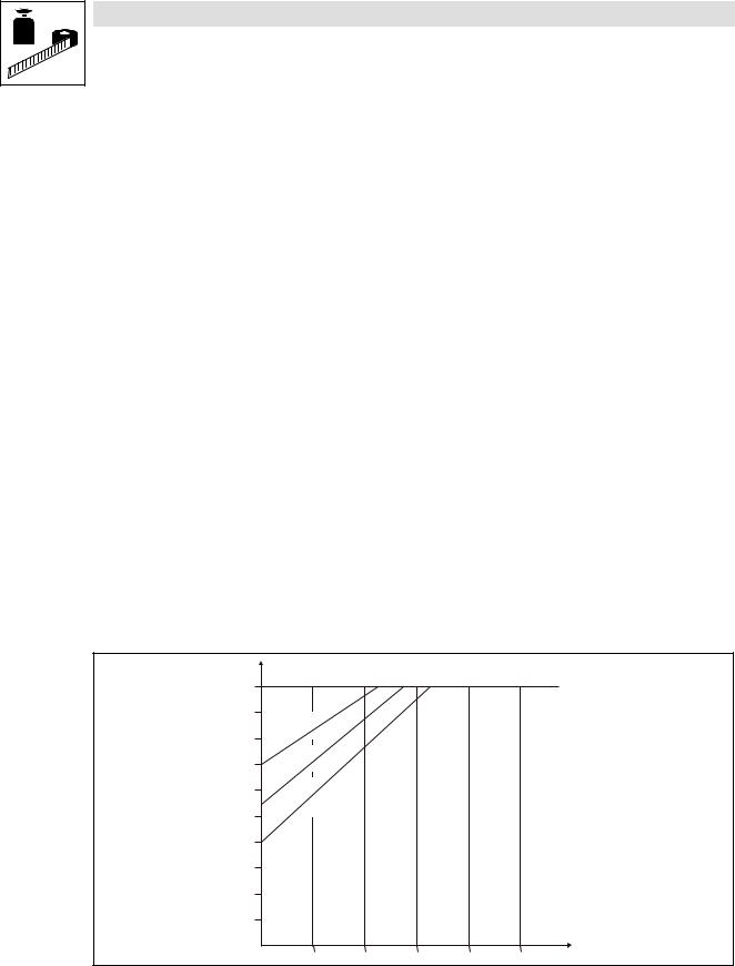
Technical data
Rated data at 400/500 V mains voltage
Fuses and cable cross−sections
8200 motec |
|
|
|
|
Operation with increased rated power |
|
|
|
||
|
|
|
|
|
|
|
|
|
|
|
|
|
|
|
Installation acc. to EN 60204−1 |
Installation acc. to UL 1) |
|
||||
Type |
|
System |
Fuse |
|
Circuit breaker |
L1, L2, L3, PE |
Fuse |
L1, L2, L3, PE |
FI |
|
|
[kW] |
|
|
|
|
[mm2] |
|
|
[AWG] |
|
|
|
|
|
|
|
|
|
|||
E82MV551_4B |
0.75 |
|
M6 A |
|
B6 A |
1 |
5 A |
18 |
|
|
|
|
|
|
|
|
|
|
|
|
|
E82MV751_4B |
1.1 |
|
M6 A |
|
B6 A |
1 |
5 A |
18 |
³ 30 mA 2) |
|
|
|
|
|
|
|
|
|
|
|
|
E82MV152_4B |
2.2 |
3/PE AC |
M10 A |
|
B10 A |
1.5 |
10 |
A |
16 |
|
|
|
|
|
|
|
|
|
|
|
|
E82MV222_4B |
3.0 |
320 ... 440 V; |
M10 A |
|
B10 A |
1.5 |
10 |
A |
16 |
|
E82MV302_4B |
4.0 |
45 ... 65 Hz |
M16 A |
|
B16 A |
2.5 |
15 |
A |
14 |
|
|
|
|
|
|
|
|
|
|
|
³ 300 mA 2) |
E82MV402_4B |
5.5 |
|
M20 A |
|
B20 A |
4.0 |
20 |
A |
12 |
|
E82MV552_4B |
7.5 |
|
M32 A |
|
B32 A |
6.0 |
25 |
A |
10 |
|
|
|
|
|
|
|
|
|
|
|
|
1)Only use UL−approved cables, fuses, and fuse holders.
UL fuse: voltage 500 ... 600 V, tripping characteristic "H", "K5" or "CC"
2)Universal−current sensitive earth−leakage circuit breaker
Observe national and regional regulations
Current derating
Depending on the operating conditions and the use of the 8200 motec, the types E82MV302_4B to EMV552_4B may require a reduction of the rated output current in continuous operation:
8200 motec mounted on... |
Current derating |
|
|
...Lenze motor/forced ventilated geared motor |
not required |
|
|
...Lenze motor/self−ventilated geared motor |
see illustration below |
|
|
...Lenze motor/self−ventilated geared motor with E82ZMV supplementary module |
not required |
|
|
...no Lenze motor/geared motor Þ E82ZMV supplementary module is always required |
not required |
|
|
...the wall (wall mounting) Þ E82ZMV supplementary module is always required |
not required |
I/IN |
|
|
|
|
|
|
|
|
|
|
|
|
|
1 |
|
|
|
|
|
|
|
|
|
|
|
|
|
0,9 |
|
|
|
|
|
|
|
|
|
|
|
|
|
|
|
|
|
|
|
|
|
B |
|
|
|
|
|
|
|
|
|
|
|
|
|
4 |
|
|
|
|
|
|
|
|
|
|
|
_ |
|
|
|
|
|
||
|
|
|
|
|
2 |
|
|
|
|
|
|
||
|
|
|
|
0 |
|
|
|
|
|
|
|
|
|
0,8 |
|
|
|
3 |
|
|
|
|
|
|
|
|
|
|
|
|
V |
|
|
|
|
|
|
|
|
|
|
|
|
|
M |
|
|
|
|
|
|
|
|
|
|
|
|
2 |
|
|
|
|
|
|
|
|
|
|
|
|
8 |
|
|
|
|
|
|
|
|
|
|
|
|
|
E |
|
|
|
|
|
|
B |
|
|
|
|
|
|
|
|
|
|
|
|
|
|
|
|
|
|
|
|
|
|
|
|
|
|
4 |
|
|
|
|
|
|
0,7 |
|
|
|
|
_ |
|
|
|
|
|
|
||
|
|
|
|
2 |
|
|
|
|
|
|
|
||
|
|
|
|
0 |
|
|
|
|
|
|
|
|
|
|
|
|
|
4 |
|
|
|
|
|
|
|
|
|
|
|
|
|
V |
|
|
|
|
|
|
|
|
|
|
|
|
M |
|
|
|
|
|
|
|
|
|
|
|
|
2 |
|
|
|
|
|
|
|
|
|
|
|
0,6 |
8 |
|
|
|
|
|
B |
|
|
|
|
|
|
E |
|
|
|
|
|
|
|
|
|
|
|
||
|
|
|
|
|
|
|
4 |
|
|
|
|
|
|
|
|
|
|
|
_ |
|
|
|
|
|
|
||
|
|
|
|
|
2 |
|
|
|
|
|
|
|
|
|
|
|
|
5 |
|
|
|
|
|
|
|
|
|
|
|
|
|
5 |
|
|
|
|
|
|
|
|
|
0,5 |
|
|
|
V |
|
|
|
|
|
|
|
|
|
|
|
M |
|
|
|
|
|
|
|
|
|
||
|
|
2 |
|
|
|
|
|
|
|
|
|
|
|
|
8 |
|
|
|
|
|
|
|
|
|
|
|
|
|
E |
|
|
|
|
|
|
|
|
|
|
|
|
0,4 |
|
|
|
|
|
|
|
|
|
|
|
|
|
0,3 |
|
|
|
|
|
|
|
|
|
|
|
|
|
0,2 |
|
|
|
|
|
|
|
|
|
|
|
|
|
0,1 |
|
|
|
|
|
|
|
|
|
|
|
|
|
|
|
|
|
|
|
|
|
10 |
20 |
30 |
40 |
50 |
f [Hz] |
Fig. 3−2 |
Reduction of the rated output current in continuous operation at 40°C ambient temperature and a switching frequency of |
|
|
4 kHz |
|
|
I |
Reduced output current 8200 motec |
|
IN |
Rated output current 8200 motec at a switching frequency of 4 kHz |
|
f |
Output frequency 8200 motec [Hz] |
3−10 EDB82MV752 EN 5.2
L

Installation
Mechanical installation − Important notes
4Installation
4.1Mechanical installation
4.1.1Important notes
·The 8200 motec frequency inverter can be used in all operating positions.
·Free space:
–Allow a free space of 100 mm above and below the inverter.
–Ensure unimpeded ventilation of cooling air and outlet of exhaust air.
Tip!
The installation of compact drives, mechanical motor mounting or wall mounting is described in the corresponding Mounting Instructions.
4.1.2Mechanical design
Type |
Cable connections |
|
Weight |
|
|
|
|
|
|
E82MV251_2B |
4 M20 |
(thread length 10 mm, without counter nut) |
1.8 kg |
|
E82MV371_2B |
2 M16 |
|||
|
|
|||
|
|
|
|
|
E82MV551_4B |
2 M25 |
(thread length 10 mm, without counter nut) |
|
|
E82MV751_4B |
4 M16 |
|
||
|
2.8 kg |
|||
|
|
|
||
|
1 M20 |
for motor cable used for wall mounting (EMC cable connection) |
||
|
|
|||
|
|
(thread length 10 mm, with counter nut) |
|
|
|
|
|
|
|
E82MV152_4B |
1 M20 |
|
|
|
E82MV222_4B |
2 M25 |
(thread length 10 mm, without counter nut) |
|
|
|
4 M16 |
|
4.1 kg |
|
|
|
|
|
|
|
1 M20 |
for motor cable used for wall mounting (EMC cable connection) |
|
|
|
|
(thread length 10 mm, with counter nut) |
|
|
|
|
|
|
|
E82MV302_4B |
|
|
|
|
|
|
|
|
|
E82MV402_4B |
3 M25 |
(thread length 10 mm, without counter nut) |
9.7 kg |
|
E82MV552_4B |
4 M16 |
|||
|
|
|||
|
|
|
|
|
E82MV752_4B |
|
|
|
|
|
|
|
|
L
EDB82MV752 EN 5.2 |
4−1 |

Installation
Mechanical installation − Dimensions
4.1.3 |
Dimensions |
|
8200mot001 |
Fig. 4−1 |
Dimensions 0.25 ... 2.2 kW |
|
a [mm] |
b [mm] |
c [mm] |
d [mm] |
[mm] |
f [mm] |
|
E82MV251_2B |
138 |
100 |
90 |
190 |
7 |
12 |
|
E82MV371_2B |
|||||||
|
|
|
|
|
|
||
E82EV551_4B |
156 |
151 |
135 |
202 |
15 |
26 |
|
E82EV751_4B |
|||||||
|
|
|
|
|
|
||
E82EV152_4B |
176 |
167 |
151 |
230 |
15 |
26 |
|
E82EV222_4B |
|||||||
|
|
|
|
|
|
|
|
|
|
|
|
82mot443 |
|
|
|
|
|
|
|
|
|
Fig. 4−2 |
Dimensions 3 ... 7.5 kW |
|
|
|
|
|
|
|
|
|
|
|
|
|
|
|
Type |
a [mm] |
b [mm] |
c [mm] |
d [mm] |
[mm] |
|
|
|
|
|
|
|
|
|
|
E82MV302_4B |
|
|
|
|
|
|
|
|
|
|
|
|
|
|
|
E82MV402_4B |
211 |
163 (223**) |
148 |
325 |
15 |
|
|
|
|
|||||
|
E82MV552_4B |
|
|||||
|
|
|
|
|
|
|
|
|
|
|
|
|
|
|
|
|
E82MV752_4B |
|
|
|
|
|
|
|
|
|
|
|
|
|
|
**for wall mounting or with fan module (type E82ZMV, dimensions L x W x H [mm]: 325 x 211 x 60), see also Instructions enclosed in the fan module.
4−2 |
EDB82MV752 EN 5.2 |
L |

Installation
Electrical installation − Important notes
4.2Electrical installation
4.2.1Important notes
Stop !
The controller contains electrostatic sensitive devices!
Before working in the connection area, the personnel must be free of electrostatic charges.
4.2.1.1Protection of persons
Danger!
Before working on the controller, check whether all power terminals (device version 001 or 151) and the pins of the FIF interface are dead, because
·the power terminals U, V, W, BR0, BR1, BR2 and the pins of the FIF interface remain live for at least 1 minute after power−off.
·the power terminals L1, L2, L3; U, V, W, BR0, BR1, BR2 and the pins of the FIF interface remain live when the motor is stopped.
·the relay outputs K11, K12, K14 (device version 001 or 151) can be live if the controller is disconnected from the mains.
Use of earth−leakage circuit breakers (^4−5)
Pluggable terminal strips
Plug in or pull off all pluggable terminals in deenergised state only!
Replacing defective fuses
Replace defective fuses with the prescribed type only when no voltage is applied.
Disconnecting the controller from the mains
The controller can be safely disconnected from the mains only via a contactor on the input side.
4.2.1.2Motor protection
·Extensive protection against overload:
–By overcurrent relay or temperature monitoring.
–We recommend to use PTC thermistors or thermal contacts for motor temperature monitoring. (Lenze three−phase AC motors are equipped with thermal contacts (NC contacts) as standard)
–PTC thermistors or thermal contacts can be connected to the controller.
·Only use motors the insulation of which is suitable for inverter operation:
–Insulation resistance: min. û = 1.5 kV, min. du/dt = 5 kV/μs
–Lenze three−phase AC motors are designed for inverter operation.
–When using motors with an unknown insulation resistance, please contact your motor supplier.
L
EDB82MV752 EN 5.2 |
4−3 |

Installation
Electrical installation − Important notes
4.2.1.3Mains types/mains conditions
Please observe the restrictions of each mains type!
System |
Controller operation |
Notes |
|
|
|
with earthed neutral |
No restrictions |
Comply with the rated data of the |
(TT/TN systems) |
|
controllers. |
|
|
|
with isolated neutral |
possible if the controller is protected in the event of an earth fault in the |
In the event of an earth fault at the |
(IT systems) |
mains supply |
inverter output, a safe operation |
|
· by suitable equipment which detect the earth fault and |
cannot be ensured. |
|
· the controller is directly disconnected from the mains |
|
|
|
|
4.2.1.4Operation on public supply systems (compliance with EN 61000−3−2)
The European standard EN 61000−3−2 stipulates limit values for harmonic currents in the supply system. Non−linear consumers (e.g. frequency inverters) cause harmonic currents which "interfere" the supplying mains and may disturb other consumers. This standard helps to ensure the high quality of public mains systems and reduce the mains load.
Tip!
The standard only applies to public mains systems. Mains systems with an own transformer station as common in industry are not public. Thus, the standard does not apply to them.
If a device or machine consists of several components, the limit values defined in the standard apply to the entire unit.
If you observe all measures given, the controllers comply with the limit values according to EN 61000−3−2. The machine/system manufacturer is responsible for the compliance with the requirements for the machine/system:
|
Supply voltage |
Power |
Measure |
|
|
|
|
|
|
8200 motec |
[V] |
[kW] |
|
|
|
|
|
|
|
E82MV251_2B |
1/N/PE AC 230 V |
0.25 |
Use ELN1−0900H005 mains choke |
|
|
|
|||
E82MV371_2B |
0.37 |
|||
|
|
|||
|
|
|
|
|
E82MV551_4B |
3/PE AC 400 V |
0.55 |
Use EZN3A1500H003 mains choke |
|
|
|
|||
E82MV751_4B |
0.75 |
|||
|
|
|||
|
|
|
|
4−4 EDB82MV752 EN 5.2
L

Installation
Electrical installation − Important notes
4.2.1.5Operation with earth−leakage circuit breaker
Danger!
The controllers have an internal mains rectifier. In the event of a short circuit to frame, a DC residual current can prevent the activation of the AC−sensitive or pulse−current sensitive earth−leakage circuit breakers and thus block the protective function for all electrical equipment operated on this earth−leakage circuit breaker.
·We recommend the following to protect persons and animals (DIN VDE 0100):
–Pulse current sensitive earth−leakage circuit breakers in systems where controllers are connected to a single−phase mains (L1/N).
–Universal−current sensitive earth−leakage circuit breakers in systems where controllers are connected to a three−phase mains (L1/L2/L3).
·Earth−leakage circuit breakers must only be installed between mains supply and controller.
·Earth−leakage circuit breakers can be misactivated by
–capacitive compensation currents of the cable shields during operation (especially with long, shielded motor cables),
–simultaneous connection of several controllers to the mains,
–use of additional interference filters.
4.2.1.6Interaction with compensation equipment
·Controllers only consume very little reactive power of the fundamental wave from the AC mains. Therefore, a compensation is not necessary.
·If you operate the controllers on a mains with compensation equipment, the compensation equipment must be provided with chokes.
–For this purpose please contact the supplier of the compensation equipment.
L
EDB82MV752 EN 5.2 |
4−5 |
 Loading...