


|
© KROHNE 12/2002 |
7.30924.31.00 |
|
|
|
|
|
|
|
|
|
|
|
|
|
|
|
||
|
|
|
|
|
|
|
|||
|
|
|
|
|
|
|
|
|
|
|
|
|
|
|
|
|
|
|
|
|
|
|
|
|
|
|
|
|
|
|
|
|
|
|
|
|
|
|
|
Addition to the
installation and operating instructions
ALTOFLUX IFS 4000 F-EEx
PROFIFLUX IFS 5000 F-EEx
VARIFLUX IFS 6000 F-EEx
Electromagnetic primary head (remote design)
Variable area flowmeters
Vortex flowmeters
Flow controllers
Electromagnetic flowmeters
Ultrasonic flowmeters
Mass flowmeters
Level measuring instruments
Communications technology
Engineering systems & solutions
Switches, counters, displays and recorders
Heat metering
Pressure and temperature

WARNING ! No changes regarding safety may be made to the devices. Unauthorized changes might affect the explosion safety of the devices.
Be sure to follow these instructions !
IMPORTANT ! • The prescriptions and regulations as well as the electrical data described in the EC-type examination certificate must be obeyed.
•Beside the instructions for electrical installations in non-hazardous locations according to the applicable national standard (e.g. IEC 364), especially the regulations in EN 60079-14 "Electrical installations in hazardous locations" or equivalent national standard must be followed.
•Installation, establishment, utilization and maintenance are only allowed to be executed by personnel with an education in explosion safety !
These additional instructions are an extension to the “Installation and Operating Instructions” and only apply to the EEx version of the IFS 4000 F, IFS 5000 F and IFS 6000 F electromagnetic primary heads in remote design. All technical information described in the “Installation and Operating Instructions” are applicable, when not specifically excluded, completed or replaced by the instructions in these additional instructions.
Contents
1 |
System components |
3 |
1.1 |
General information ALTOFLUX IFS 4000 F-EEx |
3 |
1.1.1 |
Mechanical construction |
5 |
1.1.2 |
Data plates of ALTOFLUX IFS 4000 F-EEx |
5 |
1.2 |
General information PROFIFLUX IFS 5000 F-EEx |
6 |
1.2.1 |
Mechanical construction |
7 |
1.2.2 |
Data plates of PROFIFLUX IFS 5000 F-EEx |
7 |
1.3 |
General information VARIFLUX IFS 6000 F-EEx |
8 |
1.3.1 |
Mechanical construction |
9 |
1.3.2 |
Data plates of VARIFLUX IFS 6000 F-EEx |
9 |
1.4 |
Block diagram |
10 |
2 |
Electrical connection |
11 |
2.1 |
Primary fuse connection (only for IFS 5000 F-EEx and IFS 6000 F-EEx) |
11 |
2.2 |
Fuse protection of field coil circuit |
11 |
2.3 |
Equipotential bonding system |
11 |
2.4 |
Intermediate junction box ZD-EEx |
11 |
2.5 |
Connecting cables |
12 |
2.6 |
Connection diagrams |
14 |
3 |
Maintenance |
16 |
4 |
Declaration of conformity |
17 |
5 |
EC-type examination certificates |
18 |
5.1 |
ALTOFLUX IFS 4000 F-EEx certificate |
18 |
5.2 |
PROFIFLUX IFS 5000 F-EEx certificate |
24 |
5.3 |
VARIFLUX IFS 6000 F-EEx certificate |
27 |
|
|
|
2 |
ALTOFLUX IFS 4000F-EEx, PROFIFLUX IFS 5000F-EEx, VARIFLUX IFS 6000F-EEx |
|

1 System components
1.1General information ALTOFLUX IFS 4000 F-EEx
The ALTOFLUX IFS 4000 F-EEx electromagnetic primary head in remote design (F = field) complies with the European Directive 94/9 EC (ATEX 100a) and has been approved for hazardous classified locations of Zone 1 and 2 by the KEMA conform to the European Standards of the
EN 500xx series.
They have the following approval number:
KEMA 01 ATEX 2263 X
The IFS 4000 F-EEx primary head is designed for ambient temperatures in the range of -40°C up to +60°C inclusive. The IFS 4000 F-EEx primary head in remote design is connected to an associated signal converter, e.g. IFC 090 F/…-EEx, which is also approved in accordance with the European Directive 94/9 EC (ATEX 100a). The signal converter is installed on a distance from the IFS 4000 F- EEx primary head and connected via a field coil cable, an electrode cable and a bonding wire.
The IFS 4000 F-EEx primary head in remote design can be installed in environments that are classified as Zone 1 or Zone 2 hazardous locations. The maximum permissible process liquid temperature is dependent on the maximum ambient temperature (Ta) that can occur in that environment too.
For installation of the IFS 4000 F-EEx primary head please conform to the following listed three temperature classification tables on the next page. The first column lists the temperature classes for gases and the second one the rating for dusts.
The first table applies to meter sizes larger and equal to DN300, which have type of protection increased safety "EEx e".
The second table applies to meter sizes DN25 up to DN150 inclusive, which are performed as type of protection flameproof enclosure "EEx d".
The third table applies to meter sizes DN10-20 (type protection increased safety “EEx e” and encapsulation “EEx m”) and DN200-300 (increased safety “EEx e” and powder filling “EEx q”).
The following three tables only give the maximum possible temperatures for a lining material inside the measuring tube of the primary head that consists of PFA. For information on temperature restrictions of other lining materials, see Standard Installation and Operating Instructions.
ALTOFLUX IFS 4000F-EEx, PROFIFLUX IFS 5000F-EEx, VARIFLUX IFS 6000F-EEx |
3 |
Temperature classification of meter sizes larger than DN300
Temperature |
Max. surface |
Maximum process liquid temperature |
|
||
class |
temperature |
Ta ≤ 40 °C |
Ta ≤ 50 °C |
|
Ta ≤ 60 °C |
T6 |
T 85°C |
60°C |
60°C |
|
60°C |
T5 |
T100°C |
80°C |
75°C |
|
75°C |
T4 |
T135°C |
115°C |
115°C |
|
115°C |
T3 |
T180°C |
160°C |
150°C |
|
140°C |
Use heat-resistant |
cables above |
- |
145°C |
|
110°C |
Temperature classification of meter sizes DN25…150 |
|
|
|
||
Temperature |
Max. surface |
Maximum process liquid temperature |
|
||
class |
temperature |
Ta ≤ 40 °C |
Ta ≤ 50 °C |
|
Ta ≤ 60 °C |
T6 |
T 85°C |
70°C |
70°C |
|
70°C |
T5 |
T100°C |
85°C |
85°C |
|
85°C |
T4 |
T135°C |
120°C |
120°C |
|
120°C |
T3 |
T180°C |
180°C |
180°C |
|
180°C |
Use heat-resistant |
cables above |
- |
155°C |
|
105°C |
Temperature classification of meter sizes DN10-20 and DN200-300 |
|
||||
Temperature |
Max. surface |
Maximum process liquid temperature |
|
||
class |
temperature |
Ta ≤ 40 °C |
Ta ≤ 50 °C |
|
Ta ≤ 60 °C |
T6 |
T 85°C |
75°C |
70°C |
|
70°C |
T5 |
T100°C |
95°C |
90°C |
|
75°C |
T4 |
T135°C |
130°C |
115°C |
|
75°C |
T3 |
T150°C |
150°C |
115°C |
|
75°C |
IMPORTANT ! The maximum process liquid temperature values in the above listed tables only apply to a lining material of PFA (maximum operating temperature of 200°C). For other lining materials (e.g. rubber) is a lower process liquid temperature required for safe operation. See the standard Installation and Operating Instructions for detailed information about other lining materials.
The IFS 4000 F-EEx is marked with one of the following EEx-codes, which depends on the meter size range (see table below).
Marking IFS 4000 F-EEx-code
Meter size |
EEx-code |
DN10… DN20 |
II 2GD EEx me ib IIC T6…T3 |
DN25… DN150 |
II 2GD EEx de ib IIC T6…T3 |
DN200…DN300 |
II 2GD EEx qe ib IIC T6…T3 |
larger than DN300 |
II 2GD EEx e ib IIC T6…T3 |
Also see the EC-type examination certificate in Section 5 of these additional instructions.
4 ALTOFLUX IFS 4000F-EEx, PROFIFLUX IFS 5000F-EEx, VARIFLUX IFS 6000F-EEx
1.1.1 Mechanical construction
The IFS 4000 F-EEx primary head is the measuring unit of the flowmetering system (see block diagram in section 1.4). It contains two field coils and two electrodes in type of protection intrinsic safety category "ib" according to EN 50020. The type of protection of the field coils depends on the meter size:
DN10…DN20 |
Increased safety “e” according to EN 50019 and |
|
encapsulation “m” according to EN 50028 |
DN25…DN150 |
Flameproof enclosure “d” according to EN 50018 |
DN200...DN300 |
Increased safety “e” according to EN 50019 and |
|
powder filling “q” according to EN 50017 |
larger than DN300 |
Increased safety “e” according to EN 50019 |
The electrode circuits are wired by separate shielded cables and marked by the sheath color (white and purple). The intrinsical safe "EEx ib" electrode circuits inside the IFS 4000 F-EEx primary head have the following maximum values (entity parameters):
Maximum input voltage |
Umax |
= 20 V |
Maximum input current |
Imax |
= 175 mA |
Maximum internal capacitance |
Ci |
= 0 |
Maximum internal inductance |
Li |
= 0 |
The two field coils inside the primary head are connected in series and have a maximum resistance of 85 Ω per coil with a wire diameter of at least 0.25 mm and insulation class H (Tmax ≥ 180°C) according to IEC 85. The field coils are supplied with a square-wave signal with a voltage of ± 40 V and a nominal current of 125 mA. The coil circuit is protected by two 160 mA series fuses, which are installed inside the associated signal converter unit (e.g. IFC 090 F/…-EEx).
NOTE: In case of meter size DN200-300 the coil housing is factory sealed. Do not open.
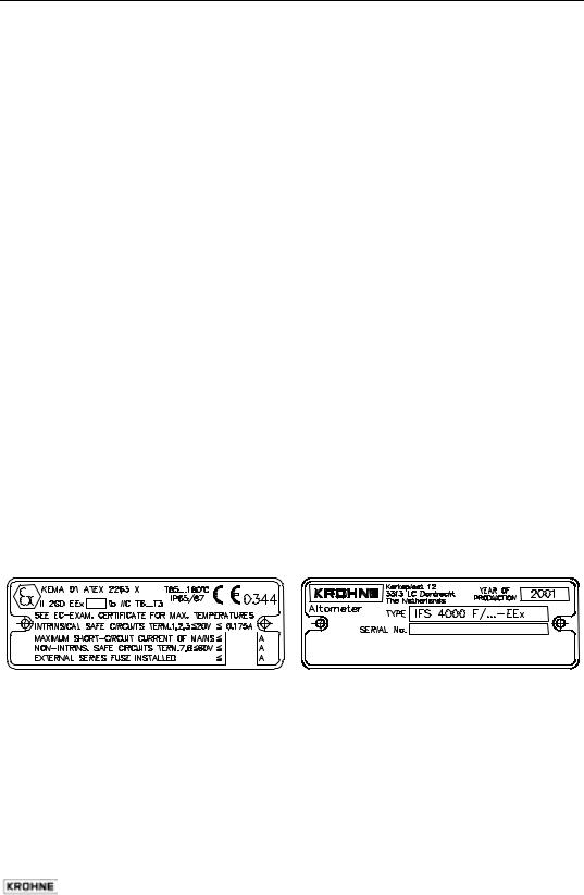
1.1.2 Data plates of ALTOFLUX IFS 4000 F-EEx
Data plate 1 Data plate 2
|
|
|
|
|
|
|
|
|
|
|
|
ALTOFLUX IFS 4000F-EEx, PROFIFLUX IFS 5000F-EEx, VARIFLUX IFS 6000F-EEx |
5 |
||||

1.2General information PROFIFLUX IFS 5000 F-EEx
The PROFIFLUX IFS 5000 F-EEx electromagnetic primary head in remote design (F = field) complies with the European Directive 94/9 EC (ATEX 100a) and has been approved for hazardous classified locations of Zone 1 and 2 by the KEMA conform to the European Standards of the EN 500xx series.
They have the following approval number:
KEMA 02 ATEX 2024 X
The IFS 5000 F-EEx primary head with meter sizes DN2.5 up to and including DN15 is designed for ambient temperatures in the range of -40°C to +60°C. The meter sizes DN25 up to DN100 inclusive are designed for ambient temperatures ranging from -20°C to +60°C.
The IFS 5000 F-EEx primary head in remote design can be installed in environments that are classified as Zone 1 or Zone 2 hazardous locations. The maximum permissible process liquid temperature is dependent on the maximum ambient temperature (Ta) that can occur in that environment too.
For installation of the IFS 5000 F-EEx primary head please conform to the below listed temperature classification table. The first column lists the temperature classes for gases and the second one the rating for dusts.
The table below applies for all meter sizes D2.5 up to and including DN100.
Temperature classification
Temperature |
Max. surface |
Maximum process liquid temperature |
|
||
class |
temperature |
Ta ≤ 40 °C |
Ta ≤ 50 °C |
|
Ta ≤ 60 °C |
T6 |
T 80°C |
65°C |
65°C |
|
65°C |
T5 |
T 95°C |
85°C |
85°C |
|
80°C |
T4 |
T130°C |
125°C |
125°C |
|
120°C |
T3 |
T180°C |
180°C |
165°C |
|
145°C |
Use heat-resistant |
cables above |
165°C |
130°C |
|
100°C |
The IFS 5000 F-EEx primary head in remote design is connected to a signal converter, e.g. IFC 090 F/…-EEx, which is also approved according to the European Directive 94/9 EC (ATEX 100a). The signal converter is installed on a distance from the IFS 5000 F-EEx primary head and connected via a field coil cable, an electrode cable and a bonding wire.
The IFS 5000 F-EEx is marked with the following EEx-code:
II 2GD EEx me ib IIC T6…T3
Also see the EC-type examination certificate in Section 5 of these additional instructions.
6 ALTOFLUX IFS 4000F-EEx, PROFIFLUX IFS 5000F-EEx, VARIFLUX IFS 6000F-EEx
1.2.1 Mechanical construction
The IFS 5000 F-EEx primary head is the measuring unit of the flowmetering system (see block diagram in section 1.4). It contains two field coils and two electrodes in type of protection intrinsic safety category "ib" according to EN 50020. The type of protection of the field coils is Encapsulation "m" according to EN 50028 and Increased Safety "e" according to EN 50019.
The electrode circuits are wired by separate shielded cables and marked by the color of the outer insulation sheath of the cable (white and purple). The intrinsical safe "EEx ib" electrode circuits inside the IFS 5000 F-EEx primary head have the following maximum values (entity parameters):
Maximum input voltage |
Umax |
= 20 V |
Maximum input current |
Imax |
= 170 mA |
Maximum internal capacitance |
Ci |
= 0 |
Maximum internal inductance |
Li |
= 0 |
The two field coils inside the primary head are connected in series and have a maximum resistance of approximately 60 Ω per coil with a wire diameter of at least 0.25 mm and insulation class H (Tmax ≥ 180°C) according to IEC 85. The field coils are supplied with a square-wave signal with a voltage of ± 40 V and a nominal current of 125 mA. The coil circuit is protected by two 160 mA series fuses, which are installed inside the associated signal converter unit (e.g. IFC 090 F/…-EEx).
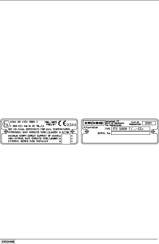
1.2.2 Data plates of PROFIFLUX IFS 5000 F-EEx
Data plate 1 |
|
Data plate 2 |
|
|
|
ALTOFLUX IFS 4000F-EEx, PROFIFLUX IFS 5000F-EEx, VARIFLUX IFS 6000F-EEx |
7 |

1.3General information VARIFLUX IFS 6000 F-EEx
The VARIFLUX IFS 6000 F-EEx electromagnetic primary head in remote design (F = field) complies with the European Directive 94/9 EC (ATEX 100a) and has been approved for hazardous classified locations of Zone 1 and 2 by the KEMA conform to the European Standards of the EN 500xx series.
They have the following approval number:
KEMA 02 ATEX 2038 X
The IFS 6000 F-EEx primary head is designed for ambient temperatures in the range of -40°C up to +60°C inclusive. The IFS 6000 F-EEx primary head in remote design is connected to a associated signal converter, e.g. IFC 090 F/…-EEx, which is also approved in accordance with the European Directive 94/9 EC (ATEX 100a). The signal converter is installed on a distance from the IFS 6000 F- EEx primary head and connected via a field coil cable, an electrode cable and a bonding wire.
The IFS 6000 F-EEx primary head in remote design can be installed in environments that are classified as Zone 1 or Zone 2 hazardous locations. The maximum permissible process liquid temperature is dependent on the maximum ambient temperature (Ta) that can occur in that environment too.
For installation of the IFS 6000 F-EEx primary head please conform to the below listed temperature classification table. The first column lists the temperature classes for gases and the second one the rating for dusts.
Temperature classification
Temperature |
Max. surface |
Maximum process liquid temperature |
|
||
class |
temperature |
Ta ≤ 40 °C |
Ta ≤ 50 °C |
|
Ta ≤ 60 °C |
T6 |
T 80°C |
70°C |
70°C |
|
70°C |
T5 |
T 95°C |
85°C |
85°C |
|
85°C |
T4 |
T130°C |
120°C |
120°C |
|
120°C |
T3 |
T190°C |
180°C |
180°C |
|
165°C |
Use heat-resistant |
cables above |
- |
160°C |
|
115°C |
The IFS 6000 F-EEx is marked with one of the following EEx-codes, which depends on the meter size range (see table below).
Marking IFS 6000 F-EEx code
Meter size |
EEx-code |
DN2.5…DN15 |
II 2GD EEx me ib IIC T6…T3 |
DN25…DN80 |
II 2GD EEx de ib IIC T6…T3 |
Also see the EC-type examination certificate in section 5 of these additional instructions.
8 ALTOFLUX IFS 4000F-EEx, PROFIFLUX IFS 5000F-EEx, VARIFLUX IFS 6000F-EEx

1.3.1 Mechanical construction
The IFS 6000 F-EEx primary head is the measuring unit of the flowmetering system (see block diagram in section 1.4). It contains two field coils and two electrodes in type of protection intrinsic safety category "ib" according to EN 50020. The type of protection of the field coils depends on the meter size:
DN2.5…DN15 |
Encapsulation “m” according to EN 50028 and |
|
Increased safety “e” according to EN 50019 |
DN25…DN150 |
Flameproof enclosure “d” according to EN 50018 |
The electrode circuits are wired by separate shielded cables and marked by the sheath color (white and purple). The intrinsical safe "EEx ib" electrode circuits inside the IFS 6000 F-EEx primary head have the following maximum values (entity parameters):
Maximum input voltage |
Umax |
= 20 V |
Maximum input current |
Imax |
= 170 mA |
Maximum internal capacitance |
Ci |
= 0 |
Maximum internal inductance |
Li |
= 0 |
The two field coils inside the primary head are connected in series and have a maximum resistance of 85 Ω per coil with a wire diameter of at least 0.25 mm and insulation class H (Tmax ≥ 180°C) according to IEC 85. The field coils are supplied with a square-wave signal with a voltage of ± 40 V and a nominal current of 125 mA. The coil circuit is protected by two 160 mA series fuses, which are installed inside the associated signal converter unit (e.g. IFC 090 F/…-EEx).
1.3.2 Data plates of VARIFLUX IFS 6000 F-EEx
Data plate 1 |
|
|
|
Data plate 2 |
|
|
|
|
|
|
|
|
|
|
ALTOFLUX IFS 4000F-EEx, PROFIFLUX IFS 5000F-EEx, VARIFLUX IFS 6000F-EEx |
9 |
 Loading...