


|
© KROHNE 08/2003 |
DIN A4: 7.02264.31.00 |
|
|
|
|
|
|
|
|
|
|
|
|
|
|
|||
|
US size: 7.02264.71.00 |
|
|
|
|
|
|
|
|
|
|
|
|
|
|
|
|
||
|
|
|
|
|
|
|
|
|
|
|
|
|
|
|
|
|
|
|
|
|
|
|
|
|
|
|
|
|
|
Installation and operating instructions
IFC 110 F V2.0
IFC 110 F-EEx V2.0
Signal converters for electromagnetic flowmeters
How to use these Instructions
Flowmeters are delivered ready for operation.
The flow sensor must be installed in the pipeline as described in the instructions for installation inside the packing of the flow sensor.
– Connection of power supply (Sect. 1.1-1.2) |
Pages |
4- 5 |
|
– Electrical connection between IFC 110 F and primary head (Sect. 1.3) |
Pages |
6-13 |
|
– |
Electrical connection of outputs and inputs (Sect. 2) |
Pages 14-22 |
|
– |
Start-up (Sect. 3) |
Pages |
23 |
Power the flowmeter. THAT’S ALL. The system is operative.
Operator control of the IFC 110 F signal converter is described in Sect. 4.
Applicable to
Software Versions
●Display & control unit No. 3.19937.02.00
●A/D converter
No. 8.13393.02.00
●Outputs/inputs (I/O) No. 3.16230.01.00
Variable area flowmeters Vortex flowmeters
Flow controllers
Electromagnetic flowmeters
Ultrasonic flowmeters Mass flowmeters
Level measuring instruments Communications technology Engineering systems & solutions
Switches, counters, displays and recorders Heat metering
Pressure and temperature
Signal converter versions
The operating data are factory-set to your ordered specifications.
Standard version, with local display and control elements
Same as display version, additional with magnetic sensors (MP)
Same as display version (D + MP),
for operation with flow sensors installed in hazardous areas
Same as standard version,
but additionally with different interfaces
Items included with supply
•Signal converter in the version as ordered, see above.
•Signal cable in the version and length as ordered (standard: signal cable A, length 10 m / 30 ft)
•Condensed installation and operating manual in the ordered language for installation, electrical connection, start-up and operator control of the signal converter.
•Service Manual in english language.
Please note!
In the Installation and Operating Manual there are hints with Sect. Numbers which you can find in the Handbook / Service Manual only!
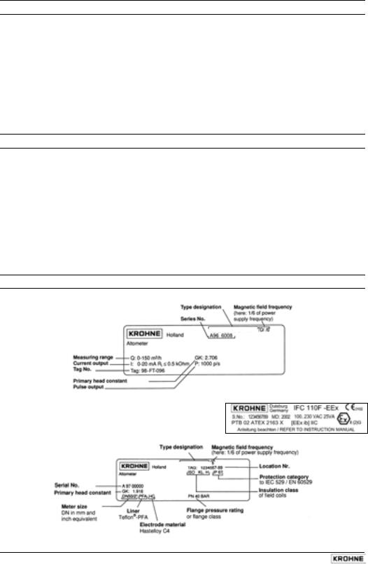
Instrument nameplates
Signal converter (example)
IFC 110 F
Signal converter IFC 110F-EEx (example)
Flow sensor (example)
ALTOFLUX 4000 F
2 |
IFC 110 F |
05/2003 |
System description
Electromagnetic flowmeters are precision instruments designed for linear flow measurement of liquid products
The process liquids must be electrically conductive:, ≥ 5 µS/cm (for cold demineralized water ≥ 20 µS/cm).
The full-scale range Q100% can be set as a function of the meter size: flow velocity of 0.3 - 12 m/s or 1 - 40 ft/s (s. Section 10.4.).
Product liability and warranty
The electromagnetic flowmeters are designed solely for measuring the volumetric flowrate of electrically conductive, liquid process products.
These flowmeters are available for use in hazardous areas.
Special regulations apply in this case, which are given in the special EEx directions.
Responsibility as to suitability and intended use of these electromagnetic flowmeters rests solelywith the operator.
Improper installation and operation of the flowmeters (systems) may lead to loss of warranty.
In addition, the “General conditions of sale” forming the basis of the purchase contract are applicable.
If flowmeters need to be returned to KROHNE, please note the information given on the last-but- one page of these Instructions. KROHNE regrets that it cannot repair or check your flowmeter(s) unless accompanied by the completed form sheet.
CE / EMC / Standards / Approvals
The here described Electromagnetic flowmeters meet the NAMUR Directive NE21, the protection requirements of Directive 89/336/EEC in conjunction with EN 61326-1 (1997) and A1 (1998), as well as Directives 73/23/EEC and 93/68/EEC in conjunction with EN 61010-1, and bear the CE marking.
Software history
Display & control unit |
Amplifier (ADC) |
Inputs and outputs (I/O) |
|||
Software |
Status |
Software |
Status |
Software |
Status |
3.19937.02.00 |
current |
8.13393.02.00 |
current |
3.16230.01.00 |
current |
|
|
|
|
|
|
IMPORTANT!
In respect of EEx versions, pay regard to all directions marked with the  symbol, and also the information given in Sect. 6.1 and 13.
Only the EEx flow sensor may be installed in the hazardous area. The EEx certified signal converter must be installed outside the hazardous area!
05/2003 |
IFC 110 F |
3 |
1 Electrical connection: power supply
1.1Location and important installation notes ……………………. PLEASE NOTE !
•Electrical connection in accordance with VDE 0100 ”Regulations for the erection of power installations with nominal voltages up to 1000 V” or equivalent national regulations.
•Do not cross or loop cables inside the terminal compartment.
•Use separate wiring (PG screwed cable entries) for power supply, field current lines, signal lines, outputs and inputs.
•Hazardous areas are subject to special regulations, see Section 6.1 and special installation instructions for hazardous-duty versions.
•Do not expose signal converter and switchgear cabinets with built-in converters to direct sunlight. Install a sunshade if necessary.
•Signal converters installed in switchgear cabinets require adequate cooling (e.g. by fans or heat exchangers).
•Do not expose signal converters to intense vibration.
•Keep the distance between the flow sensor and signal converter as small as possible, for empty pipe detection (EPD) ≤ 20 m / ≤ 66 ft. Observe maximum lengths of signal and field current lines (see Section 1.3.4).
•Use KROHNE signal line A (type DS, standard) or signal line B (type BTS, bootstrap, optional), standard length 10 m (33 ft).
•Generally use bootstrap signal lines B (type BTS) for PROFIFLUX 5000 F and VARIFLUX 6000 F flow sensors sized at DN 2.5-15 and 1/10’’-1/2’’ and for contaminated liquids which tend to form electrically insulating deposits.
•Always calibrate flow sensor and signal converter together. During installation particular care should therefore be given to identical settings of flow sensor constant GK (see instrument nameplate of flow sensor). In case GK constants are not identical, the signal converter must be adjusted to the flow sensor GK (see Sections 4 and 8.5).
•Dimensions of signal converter see Section 10.3.
IMPORTANT!
For EEx versions, also pay regard to all directions included in Sect. 6.1 and 13.
Only the EEx flow sensor may be installed in the hazardous area. The EEx certified signal converter must be installed outside the hazardous area!
4 |
IFC 110 F |
05/2003 |
1.2Power supply - connection
PLEASE NOTE !
•Type of enclosure IP 65 to IEC 529 / EN 60529 equivalent to NEMA 4/4X.
•Dimensioning: the flowmeter housing protecting the electronic equipment against dust and moisture must always be kept closed. The selected clearances and creeping distances comply with VDE 0110 and/or IEC 664 regulations for contamination grade 2. Supply circuits and output circuits are designed to meet standards of overvoltage classes III and II, respectively.
•Fuse protection, disconnecting device: fuse protection for the feeding power circuit, and also a disconnecting device (switch, circuit breaker) for isolating the signal converters must be provided (see also Sect. 1.3.5 and 1.3.6).
100-230 V AC (tolerance range 85-255 V AC)
•Observe information on the instrument nameplate, power supply voltage and frequency.
•The protective conductor PE of the power supply must be connected to the separate U-clamp terminal inside the terminal compartment of the signal converter.
•CAUTION: do not remove the internal connection (line) inside the terminal compartment of the signal converter (yellow/green wire) between the U-clamp terminal and terminal 10 - protective conductor (protection class I instrument).
•Connection diagrams I - IV for the power supply and for the electrical connection between flow sensor and signal converter, see Sections 1.3.5 (Standard) and 1.3.6 (EEx).
24 V AC / DC (tolerance ranges: AC 20.4 - 26.4 V / DC 18 - 31.2 V)
•Observe information on the instrument nameplate, power supply voltage and frequency.
•For technical reasons concerning the measuring process, a functional grounding conductor FE has to be connected to the separate U-clamp terminal inside the terminal compartment of the signal converter.
•A facility providing a reliable electrical separation (PELV) has to be provided for connections to functional extra-low voltages (24 V AC / DC) - (VDE 0100 / VDE 0106 and/or IEC 364 /
IEC 536 or equivalent national regulations).
•Connection diagrams I - IV for the power supply and for the electrical connection between flow sensor and signal converter, see Sections 1.3.5 (Standard) and 1.3.6 (EEx).
IMPORTANT!
For EEx versions, also pay regard to all directions included in Sect. 6.1 and 13.
Only the EEx flow sensor may be installed in the hazardous area. The EEx certified signal converter must be installed outside the hazardous area!
Warning: Instrument must be properly grounded to avoid personnel shock hazard.
05/2003 |
IFC 110 F |
5 |
1.3Electrical connection of flow sensors
1.3.1 General remarks on signal lines A and B and field current line C
Proper operation of the equipment is ensured when KROHNE signal lines A and B are used with foil screen and magnetic shield.
•Signal lines must be firmly installed.
•Shields are connected via stranded drain wires.
•Underwater or underground routing is possible.
•Insulating material flame-retardant to IEC 332.1 / VDE 0742.
•Low-halogen, unplasticized signal lines which remain flexible at low temperatures.
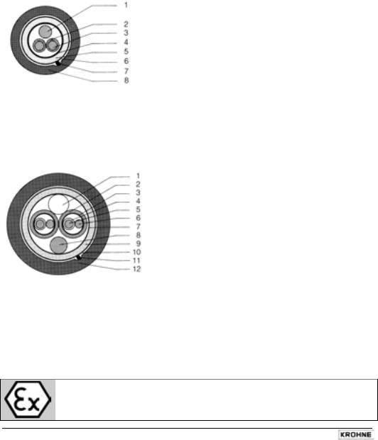
Signal line A (type DS) with double shielding
1Stranded drain wire, 1st shield, 1.5 mm² or AWG 14
2Insulation
3Stranded wire 0.5 mm² or AWG 20 (3.1 red/3.2 white)
4Special foil, 1st shield
5Insulation
6Mu-metal foil, 2nd shield
7Stranded drain wire, 2nd shield, 0.5 mm² or AWG 20
8Outer sheath
Signal line B (type BTS) with triple shielding (bootstrap line)
The bootstrap technology always controls the individual shields (3) of the signal converter exactly to the voltage which is supplied to the signal conductors (5). As this prevents voltage differences between the individual shields (3) and signal conductors (5), no current flows via the line capacitances between 3 and 5. The line capacitance seems to become ”zero”.
This allows greater cable lengths in case the electric conductivity of the liquid to be measured is low.
1Dummy glider wire
2Insulation (2.1 red/2.2 white)
3Special foil, 1st shield (3.1/3.2)
4Insulation (4.1/4.2)
5Stranded wire 0.5 mm² or AWG 20 (5.1 red/5.2 white)
6Stranded drain wire, 1st shield, 0.5 mm² or AWG 20 (6.1/6.2)
7Special foil, 2nd shield
8Stranded drain wire, 2nd shield, 1.5 mm² or AWG 14
9Insulation
10Mu-metal foil, 3rd shield
11Stranded drain wire, 3rd shield, 0.5 mm² or AWG 20
12Outer sheath
Field current line C1
Line 2 x 0.75 mm² (18 AWG) Cu or 2 x (4 x) 1.5 mm² (14 AWG) Cu (Cu = copper cross section) The cross section depends on the required cable length.
For max. permissible cable lengths please refer to Section 1.3.4
IMPORTANT!
For EEx versions, also pay regard to all directions included in Sect. 6.1 and 13.
Only the EEx flow sensor may be installed in the hazardous area. The EEx certified signal converter must be installed outside the hazardous area!
6 |
IFC 110 F |
05/2003 |
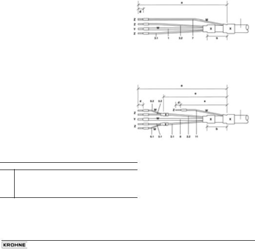
1.3.2 Stripping (preparation) of signal cables
Please note: The numbers in the drawings designate the stranded drain wires of signalling cables A and B, see sectional drawings in Sect. 1.3.1.
Flow sensor
Length |
flow sensor |
|
|
mm |
inch |
a |
90 |
3.60 |
b |
8 |
0.30 |
c |
25 |
1.00 |
d |
8 |
0.30 |
e |
70 |
2.80 |
Signal cable A (type DS), double shielding
for flow sensor
Converter
Length |
|
Converter |
|
|
mm |
|
inch |
a |
50 |
|
2.00 |
b |
8 |
|
0.40 |
d |
8 |
|
0.40 |
e |
20 |
|
0.80 |
Signal cable A (type DS), double shielding
for IFC 110 F Converter
Signal cable A bending radius ≥ 50 mm (≥ 2”)
Signal cable A bending radius ≥ 50 mm (≥ 2”)
Signal cable B (type BTS), |
Signal cable B (type BTS), |
with triple shielding (bootstrap) |
with triple shielding (bootstrap) |
for flow sensor |
for IFC 110 F Converter |
Signal cable B bending radius ≥ 50 mm (≥ 2”)
Customer-supplied materials
WInsulation tubing (PVC), Ø 2.0-2.5 mm (Ø 1”)
XHeat-shrinkable tubing or cable sleeve
YWire end sleeve to DIN 41 228: E 1.5-8
ZWire end sleeve to DIN 41 228: E 0.5-8
Signal cable B bending radius ≥ 50 mm (≥ 2”)
05/2003 |
IFC 110 F |
7 |
1.3.3 Grounding of flow sensor
•The flow sensor must be correctly connected to ground.
•The grounding cable may not transfer interference voltages.
•Do not use the grounding cable to connect more than one device to ground.
•In hazardous areas the grounding line is also used for potential equalizing purposes. Special grounding instructions are contained in the installation instructions for hazardous-duty instruments (only supplied together with such instruments).
•The flow sensor is connected to ground by means of a functional grounding conductor FE.
•Special grounding instructions for the connection of several flow sensors are contained in the separate installation instructions of the flow sensors.
•These instructions also contain detailed descriptions on how to use grounding rings and how to install flow sensors in metal or plastic pipes or in pipes which are coated on the inside.
Warning: Instrument must be properly grounded to avoid personnel shock hazard.
IMPORTANT!
For EEx versions, also pay regard to all directions included in Sect. 6.1 and 13.
Only the EEx flow sensor may be installed in the hazardous area. The EEx certified signal converter must be installed outside the hazardous area!
8 |
IFC 110 F |
05/2003 |
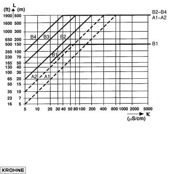
1.3.4 Cable lengths (max. distance between signal converter and flow sensor)
Abbreviations and explanations
The abbreviations used in the following tables, diagrams and connection diagrams stand for:
ASignal line A (type DS) with double shielding, max. length see diagram
BSignal line B (type BTS) with triple shielding, max. length see diagram
CField current line, minimum cross section (AF) and max. length see table
DHigh-temperature silicone line, 3x1.5 mm² (14 AWG) Cu, with single shield, max. length 5 m (16 ft)
EHigh-temperature silicone line, 2 x 1.5 mm² (14 AWG) Cu, max. length 5 m (16 ft)
AF Cross section of field current line C in Cu, see table
LCable length in m or ft
Κ Electrical conductivity of the process liquid
ZD Intermediate connection box required in connection with lines D and E for flow sensors ALTOFLUX 4000 F, PROFIFLUX 5000 F and VARIFLUX 6000 F for process temperatures exceeding 150°C (302°F).
Recommended length of signal line
for magnetic field frequencies ≤ 1/6 x power frequency
Flow |
Meter size |
|
|
|
|
Signal |
||
sensor |
DN mm |
|
|
Inch |
|
|
|
line |
VARIFLUX 6000 F |
2.5 |
- |
15 |
1/10 |
- |
|
1/2 |
B1 |
|
25 |
- |
80 |
1 |
- |
3 |
|
A1 / B3 |
PROFIFLUX 5000 F |
2.5 |
- |
|
1/10 |
- |
|
|
B1 |
|
4 |
- |
15 |
1/6 |
- |
|
1/2 |
B2 |
|
25 |
- |
100 |
1 |
- |
4 |
|
A1 / B3 |
ALTOFLUX 4000 F |
10 |
- |
150 |
3/8 |
- |
6 |
|
A1 / B3 |
|
200 |
- |
1200 |
8 |
- |
48 |
|
A2 / B4 |
ALTOFLUX 2000 F |
150 |
- |
250 |
6 |
- |
10 |
|
A2 / B4 |
ECOFLUX 1000 F |
10 |
- |
150 |
3/8 |
- |
6 |
|
A1 / B3 |
M900 |
10 |
- |
300 |
3/8 |
- |
12 |
|
A2 / B4 |
Please note!
For application with empty pipe detection (EPD) max. length < 20 m / 66 ft.
|
Max. length and minimum cross section of field current line |
|
|||
|
Length L |
|
Cross section AF (Cu), minimum |
|
|
|
0 to 150 m |
5 to 500 ft |
2 x 0.75 mm² Cu |
2 x 18 AWG |
|
|
150 to 300 m |
500 to 1000 ft |
2 x 1.50 mm² Cu |
2 x 14 AWG |
|
|
300 to 600 m |
1000 to 1900 ft |
4 x 1.50 mm² Cu |
4 x 14 AWG |
|
|
|
|
|
|
|
|
05/2003 |
|
IFC 110 F |
9 |
|
1.3.5 Connection diagrams for power supply and flow sensors
Important remarks for circuit diagrams PLEASE NOTE !
•The figures in brackets indicate the stranded drain wires of the shields (see cross-sectional drawings of signal lines in Section 1.3.1).
•Electrical connection to VDE 0100 ”Regulations for the erection of power installations with nominal voltages up to 1000 V”
•Power supply 24 V AC / DC: protective extra-low voltages (PELV) acc. to VDE 0100/
VDE 0106 and/or IEC 364/IEC 365, or corresponding national regulations.
•Systems to be used in hazardous areas are subject to special regulations applying to electrical connections (see Section 1.3.6) for hazardous-duty instruments.
• PE = protective conductor |
FE = functional ground conductor |
IMPORTANT!
Electrical connection of EEx flow sensors and EEx signal converters to be carried out as described in Sect. 1.3.6.
*Do not remove the internal connection (cable) inside the terminal compartment of the signal converter (yellow/green wire) between the U-clamp terminal and terminal 10 (protective conductor for protection class I instruments).
10 |
IFC 110 F |
05/2003 |
Process temperature below 150°C (302°F)
I |
Signal cable A (type DS) |
II |
Signal cable B (type BTS) |
|
|
|
|
|
IFC 110 F V 2.0 |
|
IFC 110 F V 2.0 |
Flow sensor |
Flow sensor |
||
|
|
|
|
|
|
|
|
|
Process temperature above 150°C (302°F) |
||
|
|
|
|
|
Signal cable A (type DS) |
|
Signal cable B (type BTS) |
III |
IV |
||
|
|
|
|
|
IFC 110 F V 2.0 |
|
IFC 110 F V 2.0 |
|
Flow sensor |
Flow sensor |
|
|
|
|
|
|
|
|
|
|
|
|
|
05/2003 |
IFC 110 F |
11 |
|
1.3.6 EEx-Connection diagrams for power supply and flow sensors
PLEASE NOTE!
•The figures in brackets indicate the stranded drain wires for the shields (see cross-sectional drawing of signal cable in Section 1.3.1).
•The connections for the intrinsically safe electrode circuit including the shield terminals are safety-separated up to a peak value of 375 V from the terminals for thepower supply,
for the inputs/outputs and for the field circuit. They are galvanically isolated from the housing (PE/PA).
•For connection of the intrinsically safe electrode circuit including shield terminals to the primary head, please refer to Item 12 in EN 60079-14.
The non-intrinsically safe field circuit to be connected to the primary head in keeping with the requirements of Item 9 in EN 60079-14 .
•The non-intrinsically safe input and output circuits may only be routed into the hazardous area in compliance with appropriate measures as specified in EN 60079-14.
•Supply power (terminals 11,12)
In conformity with current regulations for electrical installations, an isolating facility is required to be provided for the signal converter. The housing of the IFC 110 F – EEx signal converter must be incorporated in the equipotential bonding system (via external PA connection).
Note! A PE safety conductor is not connected if a functional extra-low voltage with safety separation (PELV) is used. Grounding is then carried out by way of the equipotential bonding conductor.
•Electrode circuit (terminals 1, 20, 2, 3, 30 and shield terminal S)
In conformity with the requirements for separation of intrinsically safe circuits, Category ib to EN 50 020, the cable for the intrinsically safe electrode circuit must, up to the terminals, be separated from all non-intrinsically safe circuits.
Terminals 20 and 30 are optionally provided for connecting cables with single shielding. The terminal for the outer shield (S) is capacitance grounded in the signal converter. The outer overall shield to be connected by the shortest possible wire to the shield terminal. Shields to be carefully insulated from ground and from each other.
•Field circuit FSV (terminals 7, 8)
The field circuit is all-pole protected on the FSV circuit board with an internal fusible link
160mA / 250V.
•Input/output circuits
The connection is made to functional extra-low voltage circuits with safety separation (PELV). The I/O functions and technical data are described in the Standard Installation and Operating Instructions.
IMPORTANT!
For EEx versions, also pay regard to all directions included in Sect. 6.1 and 13.
Only the EEx flow sensor may be installed in the hazardous area. The EEx certified signal converter must be installed outside the hazardous area!
*Do not remove the internal connection (cable) inside the terminal compartment of the signal converter (yellow/green wire) between the U-clamp terminal and terminal 10 (protective conductor for protection class I instruments).
12 |
IFC 110 F |
05/2003 |

Process temperature below 150°C (302°F)
I |
Signal cable A (type DS) |
II |
Signal cable B (type BTS) |
|
|
|
|
|
IFC 110 F V 2.0 |
|
IFC 110 F V 2.0 |
Hazardous area |
|
Hazardous area |
|
|
|
|
|
|
|
Flow sensor |
|
Flow sensor |
|
|
|
|
|
|
|
|
|
Process temperature above 150°C (302°F) |
||
|
|
|
|
|
Signal cable A (type DS) |
|
Signal cable B (type BTS) |
III |
IV |
||
|
|
|
|
|
IFC 110 F V 2.0 |
|
IFC 110 F V 2.0 |
Hazardous area |
|
Hazardous area |
|
|
|
Flow sensor |
Flow sensor |
05/2003 |
IFC 110 F |
13 |
 Loading...