


DIN A4: 7.10004.31.00 © KROHNE 02/2001 US size: 7.10004.71.00 
 GR/OP
GR/OP
Installation and operating instructions
ALTOFLUX 2W
IFM 4042 K
Electromagnetic flowmeters
How to use these Instructions
The flowmeters are supplied ready for operation.
– Installation in the pipeline (Section 1) |
Pages |
5-10 |
|
– |
Electrical connection (Section 2) |
Pages 11-13 |
|
– |
Start-up (Section 3) |
Page |
17 |
Power the flowmeter. THAT’S ALL. The system is operative.
Applicable to
Software Versions
●Display/Control unit No. 3.19019.xx00
●ADC module
No. 3.19749.xx00
●I/O module
No. 3.18748.xx00
Variable area flowmeters
Vortex flowmeters
Flow controllers
Electromagnetic flowmeters
Ultrasonic flowmeters
Mass flowmeters
Level measuring instruments
Communications engineering
Engineering systems & solutions
<RXU RSHUDWLQJ GDWD
Here you can note down the settings of the signal converter !
Fct. No. |
Function |
Settings |
|
|
|
|
|
1.01 |
Full-scale range |
|
|
1.02 |
Time constant |
|
|
1.03 |
Low-flow cutoff |
- ON: |
- OFF: |
1.04 |
Display |
Flow |
|
|
|
Counter |
|
|
|
Messages |
|
1.05 |
Current output |
Function |
|
|
|
Range |
|
|
|
Error |
|
|
|
|
|
1.06. |
Pulse output |
Function |
|
|
|
Pulse width |
|
|
|
Pulses / Volume |
|
1.07Status output
3.01Language
3.02 |
Primary head |
Meter size |
|
|
|
GKL value |
|
|
|
Flow direction |
|
|
|
|
|
3.4 |
Application |
Empty pipe |
|
|
|
Field current |
|
|
|
Mode field current |
|
|
|
Limit |
|
|
|
Filter |
|
|
|
|
|
|
|
|
|
3.5 |
Hardware |
Function of terminal B: |
|
|
|
|
|
3.6 |
HART |
off |
HART |
|
|
Current 4 mA trim.: |
|
|
|
Current 20 mA trim.: |
|
|
|
Address |
|
|
|
I-Multidrop: |
|
|
|
|
|
2 |
ALTOFLUX 2W |
02/2001 |

&RQWHQWV
∙ |
Your operatig data |
2 |
∙ |
System description |
4 |
∙ |
Product liability and warranty |
4 |
∙ |
CE / EMC / Standards / Approvals |
4 |
∙ |
Software history |
4 |
7HLO $ |
,QVWDOODWLRQ DQG 6WDUW XS |
|
1 |
Installation |
5 - 10 |
1.1 |
Items included with supply |
5 |
1.2 |
Handling |
5 |
1.3 |
Installation location |
6 |
1.4 |
Suggestions for installation |
7 |
1,5 |
Installation in the pipeline |
8 |
1.6 |
Torques |
9 |
1.7 |
Grounding |
10 |
2 |
Electrical connection |
11 – 16 |
2.1 |
Information on electrical connection and connection data |
11 |
2.2 |
Output circuit diagrams |
12 – 13 |
2.3 |
Characteristic of the outputs |
14 – 16 |
3 |
Start-up |
17 |
3.1 |
Power ON and measurement |
17 |
3.2 |
Factory settings |
17 |
7HLO % |
,)& 6LJQDO FRQYHUWHU |
² |
4 |
Operation of the signal converter |
18 - 33 |
4.1 |
KROHNE operator control concept |
18 |
4.2 |
Operating and check elements |
19 |
4.3 |
Function of keys |
20 – 21 |
4.4 |
Table of settable function |
22 – 32 |
4.5 |
Error messages in measuring mode |
33 |
4.6 |
Reset counter and cancel error messages |
33 |
7HLO & |
7HFKQLFDO 'DWD %ORFN GLDJUDP XQG 0HDVXULQJ SULQFLSOH |
² |
5 |
Technical Data |
34 - 40 |
5.1 |
Full-scale ranges |
34 |
5.2 |
Error limits at reference conditions |
35 |
5.3 |
IFC 040 Signal converter |
36 – 37 |
5.4 |
IFS 4002 Primary head |
38 |
5.5 |
Dimensions and weights |
39 |
5.6 |
Limits |
40 |
6 |
Block diagram of signal converter |
41 |
7 |
Measuring principle |
42 |
8 |
If you need to return flowmeters for testing or repair to KROHNE |
43 |
02/2001 |
ALTOFLUX 2W |
3 |

6\VWHP GHVFULSWLRQ
Electromagnetic 2-wire flowmeters with IFC 040 signal converter are precision instruments designed for linear flow measurement of liquid products.
The process liquids need to be electrically conductive, ³ 5 µS/cm (for cold demineralized water ³ 20 µS/cm).
Depending on the meter size, the full-scale range Q100%
can be set between 85 Liter/h and 763 m3/h, equivalent to a flow velocity v = 0,3- 12 m/s, see flow table in Section 5.1.
3URGXFW OLDELOLW\ DQG ZDUUDQW\
Electromagnetic 2-wire flowmeters with IFC 040 signal converter are designed solely for measuring the volumetric flowrate of electrically conductive, liquid process products.
These flowmeters are also available for use in hazardous areas. Special codes and regulations apply in this connection and these are referred to in the special ‘EEx’ notes.
Responsibility for suitability and intended use of these electromagnetic flowmeters rests solely with the operator.
Improper installation and operation of the flowmeters (systems) may lead to loss of warranty.
In addition, the “General conditions of sale” forming the basis of the purchase contract are applicable.
If flowmeters need to be returned to KROHNE, please note the information given on the last-but- one page of these Instructions. KROHNE regret that they cannot repair or check your flowmeter(s) unless accompanied by the completed form sheet.
&( (0& 6WDQGDUGV $SSURYDOV
Electromagnetic flowmeters with IFC 040 signal converter
meet the protection requirements of Directive 89/336/EEC in conjunction with
EN 50081-1 (1992) and EN 50082-2 (1995), and Directives 73/23/EEC and
93/68/EEC in conjunction with EN 61010-1, and also bear the CE symbol..
6RIWZDUH KLVWRU\
Display and control unit |
PC user software |
Hart® module |
|
||
IFC 040 |
|
IFC 040 |
|
|
|
Software |
Status |
Software |
Status |
Software |
Status |
3.19019.xx00 |
current |
3.19136.xx00 |
current |
3.18748.xx00 |
current |
|
|
|
|
|
|
ADC module |
|
I/O module |
|
|
|
Software |
Status |
Software |
Status |
|
|
3.19749.xx00 |
current |
3.18748.xx00 |
current |
|
|
4 |
ALTOFLUX 2W |
02/2001 |
Part A Installation and Start-up |
Section 1.1 + 1.2 |
,QVWDOODWLRQ
1.1Items included with supply
•Flowmeter in the size as ordered
•Connecting wires for grounding, refer to Section 1.7 Grounding
•Certificate of calibration data
•Grounding rings (option), if ordered
•Installation and operating instructions for the signal converter
Fitting accessories (stud bolts, screws, gaskets, etc.) are not supplied, to be provided by customer!
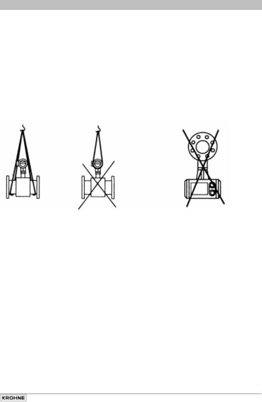
1.2 Handling
Do not lift flowmeter by the signal converter housing or the terminal box.
Do not set flowmeter down on the signal converter housing.
02/2001 |
ALTOFLUX 2W |
5 |
Section 1.3 |
Part A Installation and Start-up |
1.3 Installation location
•Temperatures
Refer to Section 5.6 “Limits“ for operating pressure and vacuum load based on flange standards and type of tube liner.
|
Ambient temperature |
Process temperature |
|
|||
Standard |
-25 to +60 °C |
-13 to + 140 °F |
-25 to |
≤ + 60 °C |
-13 to |
≤ +140 °F |
|
-25 to +40 °C |
-13 to + 104 °F |
-25 to |
≤ +140 °C |
-25 to |
≤ +284 °F |
EEx |
-25 to +60 °C |
-13 to + 140 °F |
-25 to |
≤ + 60 °C |
-13 to |
≤ +140 °F |
|
-25 to +40 °C |
-13 to + 104 °F |
-25 to |
≤ +140 °C |
-25 to |
≤ +284 °F |
Storage and handling |
-25 to +60 °C |
-13 to +140 °F |
|
|
|
|
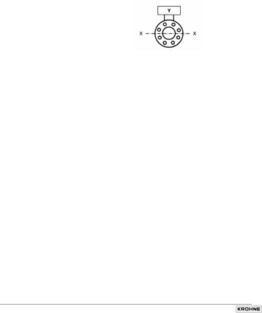
•Location and position as required, but in a horizontal pipe run electrode axis
X – • – • – • – X
should be approximately horizontal.
Y Signal converter housing
•Measuring tube must be completely filled at all times.
•Direction of flow is arbitrary: arrow on flowmeter can normally be ignored.
For exceptions, refer to Sect. 3.2 “Factory settings” in the Installation and Operating Instructions for the signal converter.
•Stud bolts and nuts: to install, make sure there is sufficient room next to the pipe flanges.
•Vibration: support pipeline on both sides of flowmeter. Level of vibration in conformity with IEC 068-2-34: below 2.2g for flowmeters in the 20-150 Hz frequency range.
•Do not expose to direct sunlight: fit a sunshade if necessary, not included with flowmeter, to be provided by customer.
•Avoid strong electromagnetic fields in vicinity of flowmeter.
• |
Inlet run 5 × DN and outlet run 2 × DN, straight pipeline, |
|
measured from electrode axis (DN = meter size) |
•Vortex and corkscrew flow: increase length of inlet and outlet runs or install flow conditioners.
•Mixing different process liquids: install flowmeter upstream of the mixing point or at an adequate distance downstream (min. 30 × DN), otherwise display may be unsteady.
•Plastic pipelines and internally coated metal pipelines: grounding rings required, refer to Sect. 1.7 “Grounding“.
•Insulated pipeline: do not insulate flowmeter.
•Zero setting: not necessary. To check, it should be possible to set “zero“ flow velocity when the measuring tube is completely filled. Shutoff valves should therefore be provided, either downstream of the flowmeter or upstream and downstream of the flowmeter.
•Electrical connection to VDE 0100 “Regulations governing heavy-current installations with line voltages up to 1000 V” or equivalent national regulations.
•Hazardous areas: subject to special regulations,
refer to special ‘EEx’ information (texts with grey background).
6 |
ALTOFLUX 2W |
02/2001 |

Part A Installation and Start-up |
Section 1.4 |
1.4 Suggestions for installation
To avoid measuring errors due to gas/air inclusion or to pipe running empty, please observe the following:
02/2001 |
ALTOFLUX 2W |
7 |
Section 1.5 |
Part A Installation and Start-up |
1.5 Installation in the pipeline
•Installation material not included, to be provided by customer (stud bolts, nuts, gaskets, etc.).
•Pipe flanges and operating pressure: refer to “limits“ tables in Section 5.6
•Distance between pipe flanges:
see fitting dimension a in Section 5.5 “Dimensions and weights“
•High-temperature service
Where process temperatures exceed 100°C/212°F, provide facilities to compensate for longitudinal expansion on heat-up of the pipeline.
For short pipelines, use resilient gaskets, and
for long pipelines install flexible pipe elements (e.g. elbows).
•Flange position: Install flowmeter in line with pipe axis. Pipe flange faces must be parallel to each other.
•Gaskets
No additional gaskets required for primary heads fitted with tube liners of Teflon® - PFA or Teflon® - PTFE. Refer to Sect. 1.6 for torques.
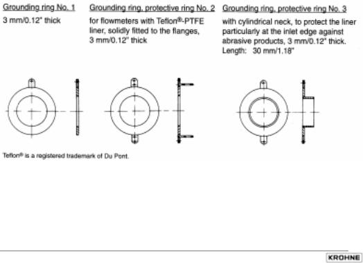
•Grounding rings / protection rings (option)
On plastic pipelines and internally coated metal pipelines, grounding rings are required to form the conductive connection with the process liquid. Refer to Sect. 7 “Grounding“ for electrical connection.
Please note: The cylindrical neck must be inside the measuring tube (to protect the liner, particularly at the inlet edge).
8 |
ALTOFLUX 2W |
02/2001 |

Part A Installation and Start-up |
Section 1.6 |
1.6 Torques
•Stud bolts: tighten uniformly in diagonally opposite sequence. See table for number and type.
•10 Nm ~ 1.0 kpm ~ 7.23 ft × lbf
Meter |
Pressure |
Bolts |
|
Max. |
|
size |
rating |
|
|
torques |
|
DN mm |
PN |
|
Nm |
|
ft × lbf |
|
|
|
|
|
|
10 |
40 |
4 × M 12 |
7.6 |
|
5.5 |
|
|
|
|
|
|
15 |
40 |
4 × M 12 |
9.3 |
|
6.7 |
|
|
|
|
|
|
25 |
40 |
4 × M 12 |
22 |
|
11 |
|
|
|
|
|
|
50 |
40 |
4 × M 16 |
55 |
|
31 |
|
|
|
|
|
|
80 |
25 |
8 × M 16 |
47 |
|
25 |
|
|
|
|
|
|
100 |
16 |
8 × M 16 |
39 |
|
30 |
|
|
|
|
|
|
150 |
16 |
8 × M 20 |
68 |
|
47 |
|
|
|
|
|
|
Meter |
Flange |
Bolts |
|
Max. |
||
size |
class |
for ANSI |
|
torques |
||
inches |
Ib |
class 150 |
Nm |
|
ft × lbf |
|
|
|
flanges |
|
|
|
|
3/8 |
150 |
4 × |
1/2" |
3.5 |
|
2.5 |
1/2 |
150 |
4 × |
1/2" |
3.5 |
|
2.5 |
1 |
150 |
4 × |
1/2" |
6.7 |
|
4.8 |
2 |
150 |
4 × |
5/8” |
24 |
|
17.4 |
3 |
150 |
4 × |
5/8” |
43 |
|
31.1 |
4 |
150 |
4 × |
5/8” |
34 |
|
24.6 |
6 |
150 |
8 × |
3/4" |
61 |
|
44.1 |
02/2001 |
ALTOFLUX 2W |
9 |
Section 1.7 |
Part A Installation and Start-up |
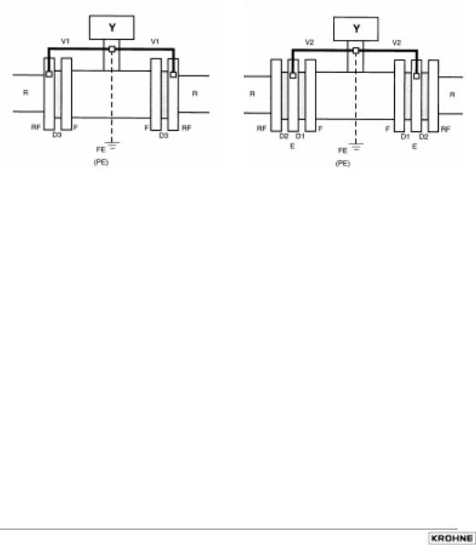
1.7 Grounding
•All flowmeters must be properly grounded to avoid personnel shock hazard.
•The ground conductor should not transmit any interference voltages, therefore do not ground any other electrical devices together with this conductor.
Repeater power supply unit
•Protective separation (PELV) must be ensured
(VDE 0100 / VDE 0106 or IEC 364 / IEC 536, or equivalent national regulations).
•For measurement reasons, connect an FE functional ground conductor.
Metal pipelines, not internally coated |
Metal pipelines, |
||||
|
|
|
with or without internal coating, |
||
|
|
|
and plastic pipelines |
||
grounding without grounding rings |
grounding with grounding rings |
||||
|
|
|
|
|
|
|
|
|
|
|
|
|
|
|
|
|
|
|
|
|
|
|
|
|
|
|
|
|
|
|
|
|
|
|
|
D1, D2, D3 |
Gaskets, not included with supply, to be provided by customer. |
E |
Grounding rings (option) |
F |
Flowmeter flanges |
FE |
Functional ground, wire ³ 4 mm2 Cu (10 AWG), not included with supply, |
R |
to be provided by customer. |
Pipeline |
|
RF |
Pipe flanges |
V1, V2 |
Interconnecting wires, included with supply |
Y |
Terminal box or signal converter |
10 |
ALTOFLUX 2W |
02/2001 |
Part A Installation and Start-up |
Section 2.1 |
(OHFWULFDO FRQQHFWLRQ
2.1 Information on electrical connection and connection data
•Rated values: The flowmeter housings protect the electronic equipment from dust and moisture and should always be kept properly closed. Creepage distances and clearances in air have been dimensioned in conformity with VDE 0110 and IEC 664 for contamination category 2. Supply circuits and output circuits are designed to meet the standards of overvoltage classes III and II, respectively.
•Safety isolation: The flowmeter must be provided with an isolating facility.
•Note information on instrument nameplate(s).
•PE conductor / FE functional ground must be connected to the separate U-clamp terminal in the terminal compartment of the signal converter.
•For measurement reasons, the flowmeter must be properly grounded. The ground conductor should not transmit any interference voltages. Therefore, do not ground any other electrical devices together with this conductor.
•In hazardous areas, the ground conductor is used simultaneously for equipotential bonding.
CAUTION: Where a power booster (1L= / 0L=) is used, electrical isolation is required between the power booster and the current output, otherwise the electronic equipment will substain irreparable damage.
Standard power terminals
EEx power terminals
|
|
|
|
|
|
|
|
FE |
Functional ground |
|
|
|
|
|
|
|
|
|
|
|
|
|
|
PE |
Safety conductor / equipotential bonding |
||||||
|
|
|
|
|
|
|
|
||||||||
|
|
|
|
|
|
|
|
||||||||
|
|
|
|
|
|
|
|
|
|
|
|
|
|
||
|
Ι |
Current output |
Vmax |
= 36 V |
Ιmax |
= |
22.4 mA (fault current) |
||||||||
|
Ι |
(not polarity sensitive) |
Vnom |
= 24 V |
Ιnom |
= |
4 - 20 mA |
|
|||||||
|
|
|
|
|
|
|
|
|
Vmin |
= 14 V |
Ιmin |
= |
3.6 mA (fault current) |
||
|
|
|
|
|
|
|
|
|
|
|
|
||||
|
B 2 |
Pulse or status output |
NAMUR terminals (B2 + B ) |
|
|
||||||||||
|
B |
NAMUR |
Ιopen |
= 0.4 mA |
Ιclosed |
= 6 mA |
|
||||||||
|
B 1 |
Pulse or status output |
High-current terminals (B1 + B ) |
|
|||||||||||
|
B |
high current |
closed: |
Vmax = |
2 V |
Ιmax |
= 100 mA |
||||||||
|
|
|
|
|
|
|
|
|
open: |
Vmax = |
36 V |
Ιmax |
= 2 mA |
||
|
|
|
|
|
|
|
|
|
|
|
Vnom = |
24 V |
Ιnom |
= 1,5 mA |
|
|
B |
Common ground (negative) |
Take note of polarity! |
|
|
|
|
||||||||
|
|
|
|
|
|
|
|
|
|
|
|
|
|
||
|
1L= |
Power booster |
2nd power terminal |
|
|
|
|
||||||||
|
0L= |
(not polarity sensitive) |
Vmax |
= 36 V |
Vmin |
= |
14 V |
|
|
||||||
|
|
|
|
|
|
|
|
|
Vnom |
= 24 V |
Ιnom |
= |
22 mA |
|
|
|
Ι + |
not used, no internal connection |
|
|
|
10 |
for internal use only |
|
|
|
|
|
|
|
|
|
|
|
|
|
02/2001 |
ALTOFLUX 2W |
11 |
|
|
Section 2.2 |
Part A Installation and Start-up |
|
|
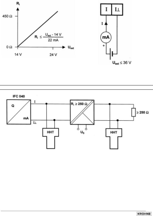
2.2 Output circuit diagrams |
|
|
|
|
|
|
|
Supply power and current output - standard |
|
|
Note data given in Sect. 2.1!
Supply power and current output - operation via repeater power supply unit
Repeater power supply unit
Repeater power supply unit, e.g.: |
|
CEAG 6 / 420 or |
|
Phoenix Contact PI/Ex-ME-RPSS-I/I |
Note data given in Sect. 2.1! |
12 |
ALTOFLUX 2W |
02/2001 |
Part A Installation and Start-up |
Section 2.2 |
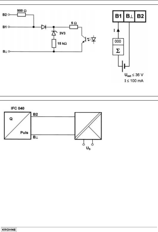
Pulse or status output
current limited to 100 mA
Note data given in Sect. 2.1!
Pulse or status output - operation via repeater power supply unit
Repeater power supply unit
Repeater power supply unit e.g.:
Phoenix PI/Ex-ME-2NAM/COC |
Note data given in Sect. 2.1! |
02/2001 |
ALTOFLUX 2W |
13 |
 Loading...