


 Loading...
E 2
Contents |
|
Introduction............................................................................ |
3 |
About the owner’s manual........................................................... |
3 |
Main features.............................................................................. |
3 |
Block diagram............................................................................. |
4 |
Controls and connections..................................................... |
5 |
Front panel controls.................................................................... |
5 |
Rear panel connections.............................................................. |
6 |
Turning the power on/off............................................................. |
7 |
Playing the minilogue xd....................................................... |
9 |
Selecting and playing a program................................................. |
9 |
Using Favorites......................................................................... |
10 |
Playing the sequencer............................................................... |
11 |
Programs.............................................................................. |
12 |
Program architecture................................................................. |
12 |
Creating sounds........................................................................ |
13 |
Saving a program...................................................................... |
14 |
Basic parameters................................................................. |
15 |
MASTER controls..................................................................... |
15 |
VCO 1/VCO 2/MULTI ENGINE section..................................... |
16 |
MIXER section.......................................................................... |
20 |
FILTER section.......................................................................... |
21 |
EG/LFO section......................................................................... |
22 |
EFFECTS section..................................................................... |
24 |
Sequencer................................................................................. |
25 |
Edit mode.............................................................................. |
30 |
How to enter the Edit mode....................................................... |
30 |
Edit mode parameter list........................................................... |
31 |
PROGRAM EDIT mode............................................................ |
32 |
SEQ EDIT mode....................................................................... |
37 |
GLOBAL EDIT mode................................................................ |
39 |
Other functions.................................................................... |
45 |
Tuning....................................................................................... |
45 |
Restoring the factory settings................................................... |
47 |
Shortcuts using the SHIFT button............................................. |
47 |
Using with other devices..................................................... |
49 |
Making connections with the SYNC IN/OUT jacks................... |
49 |
Making connections with the CV IN jacks................................. |
50 |
Connecting to a MIDI device or a computer.............................. |
50 |
Data list................................................................................. |
53 |
Effects list.................................................................................. |
53 |
Program list............................................................................... |
55 |
Specifications....................................................................... |
60 |
MIDI Implementation Chart................................................. |
61 |
2

Introduction
About the owner’s manual
The documentation for this product consists of the following:
•Precautions (included)
•Quick Start Guide (included)
Read this manual first. This guide explains the basic operations and other features of the minilogue xd.
•Owner’s Manual (what you’re reading)
This explains how to use the detailed functions of the minilogue xd
Conventions in this manual
Symbols  , Note, Tip
These symbols respectively indicate a caution, a supplementary note, or a tip.
Main features
•The minilogue xd features an analog signal path with four voices that takes after the Korg prologue analog synthesizer.
•Each voice includes a MULTI ENGINE providing a noise generator, a VPM oscillator, and the possibility to load user programmed oscillators. This instrument combines two VCOs, making it possible to create a wide variety of sounds.
•The FX section is equipped with high quality digital effects (MODULATION, REVERB, DELAY).
•500 programs (200 preset programs and 300 user programs as the factory-set default) can be called up and saved in an instant.
•Real-time oscilloscope provides visual feedback of parameter changes.
•The minilogue xd has a powerful 16-step polyphonic sequencer.
•Sync In and Sync Out jacks allow you sync analog tempo to and from other devices.
•Two CV IN jacks are available, letting you control the parameters of this instrument using a modular synthesizer or other device.
3
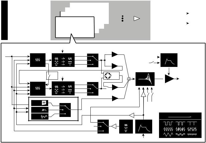
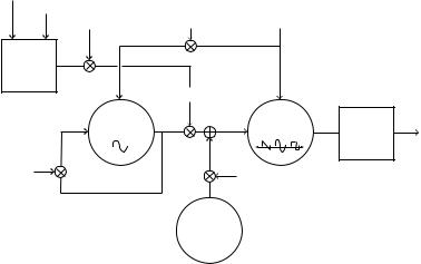
Block diagram
VOICE ASSIGNER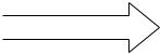
|
|
|
|
VOICE 1 |
|
|
|
|
|
|||
|
|
|
|
|
|
|
|
|
||||
|
|
|
VOICE 2 |
|
|
|
|
|
|
|||
|
|
VOICE 3 |
|
|
|
Voice Mixer |
DIGITAL |
|
OUTPUT L |
|||
|
|
|
|
|
|
|||||||
VOICE 4 |
|
|
|
|
|
|
||||||
|
|
|
|
EFFECTS |
|
OUTPUT R |
||||||
|
|
|
|
|
||||||||
|
|
|
|
|
|
|
|
|
|
|
|
|
|
|
|
|
|
|
|
|
|
|
|
|
|
|
|
|
|
|
|
|
|
|
|
|
|
|
|
|
|
|
|
|
|
|
|
|
|
|
|
|
|
|
|
|
|
|
|
|
|
|
|
|
|
|
|
|
|
|
|
|
|
|
|
|
|
VOICE |
|
|
LFO |
|
VCO1 level |
|
WAVE SHAPE |
SAW |
|||
PITCH |
VCO 1 |
|
|||
LFO |
|
|
|
TRI |
CROSS MOD |
EG |
|
|
|
SQR |
depth |
|
|
|
|
||
|
|
OSC |
LFO |
|
RING |
|
|
SYNC |
|
|
MOD |
FM |
VCO 2 |
WAVE SHAPE |
SAW |
|
|
PITCH |
|
||||
|
|
|
TRI |
|
|
LFO |
|
|
|
|
|
|
|
|
SQR |
|
|
EG |
|
|
|
VCO2 level |
|
|
|
|
|
||
PITCH |
USR |
MULTI ENGINE |
|
MULTI level |
|
USR |
|
|
|||
LFO |
VPM |
VPM |
|
|
|
EG |
NOISE |
|
|
PITCH EG int |
|
|
|
|
|||
|
|
|
|
||
|
NOISE |
|
|
|
|
|
|
|
|
|
LFO |
SHAPE LFO
gate |
|
AMP EG |
|
|
velocity
VCF
 VCA
VCA
velocity keytrack Int EG
0% |
wave shape amount |
100% |
|
EG
gate
4
Controls and connections
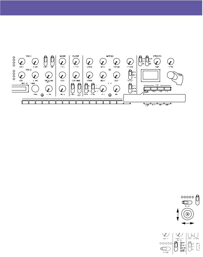
Front panel controls
This diagram shows the layout of the front panel knobs, switches, and buttons.
2. VOICE MODE section |
3. VCO 1/VCO 2/MULTI ENGINE section |
6. AMP EG/EG/LFO section |
||||
1. MASTER controls |
4. MIXER section 5. FILTER section |
7. EFFECTS section |
||||
|
|
|
|
|
|
|
8. Display
9. PROGRAM/VALUE knob
10. EDIT/SEQUENCER


 section 12. Joystick


11. Buttons 1–16
MASTER controls
MASTER knob OCTAVE switch (p.9) TEMPO knob (p.15)
PORTAMENTO knob (p.15)
1.VOICE MODE section
(p.15)
VOICE MODE DEPTH knob VOICE MODE TYPE switch
2.VCO 1/VCO 2/MULTI ENGINE section
VCO 1 (p.16) WAVE switch OCTAVE switch PITCH knob SHAPE knob VCO 2 (p.16) WAVE switch OCTAVE switch PITCH knob SHAPE knob SYNC switch RING switch
CROSS MOD DEPTH knob
MULTI ENGINE (p.17) NOISE/VPM/USR switch Display
TYPE knob SHAPE knob
3.MIXER section (p.20)
VCO 1 knob VCO 2 knob MULTI knob
4.FILTER section (p.21)
VCF
CUTOFF knob RESONANCE knob DRIVE switch KEYTRACK switch
5.AMP EG/EG/LFO section
AMP EG (p.22) ATTACK knob DECAY knob SUSTAIN knob RELEASE knob EG (p.22) ATTACK knob DECAY knob EG INT knob TARGET switch LFO (p.23) WAVE switch MODE switch RATE knob INT knob TARGET switch
6.EFFECTS section (p.24)
DEL/REV/MOD switch OFF/ON/SELECT switch TIME knob
DEPTH knob
7.Display (p.9) (p.42)
8.PROGRAM/VALUE knob
(p.9) (p.30)
9.EDIT/SEQUENCER section
EDIT (p.30)
EDIT MODE button WRITE button EXIT button
SHIFT button
SEQUENCER (p.25) MOTION MODE button PLAY button
REC button REST button
10.Buttons 1–16 (p.10) (p.28) (p.30)
11.Joystick (p.9)
5
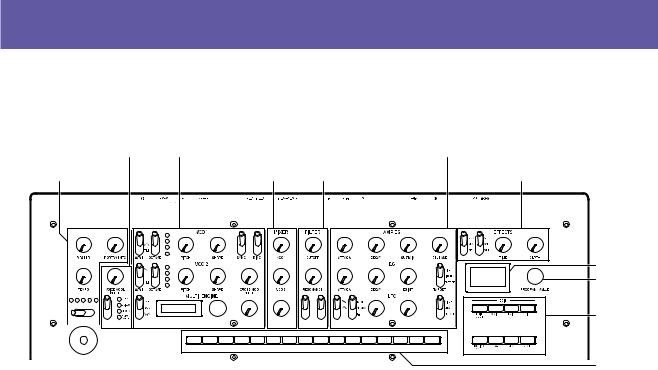
Rear panel connections
The illustration below shows a typical example of connections for the minilogue xd. Connect the minilogue xd as appropriate for your own sound system.
1. DC 9V |
|
jacks |
3. |
|
(Power) switch |
5. MIDI IN, OUT connectors |
|
7. CV IN 1, 2 jacks |
9. OUTPUT L/MONO, R jacks |
||||||||||||||||
|
|
|
|||||||||||||||||||||||
|
|
|
|||||||||||||||||||||||
|
|
2. Cord hook |
4. |
(USB B) Port |
|
|
|
|
|
6. SYNC IN, OUT jacks |
8. DAMPER jack |
10. (Headphones) jack |
|||||||||||||
|
|
|
|
|
|
|
|
|
|
|
|
|
|
|
|
|
|
|
|
|
|
|
|
|
|
|
|
|
|
|
|
|
|
|
|
|
|
|
|
|
|
|
|
|
|
|
|
|
|
|
|
|
|
|
|
|
|
|
|
|
|
|
|
|
|
|
|
|
|
|
|
|
|
|
|
|
|
|
|
|
|
|
|
|
|
|
|
|
|
|
|
|
|
|
|
|
|
|
|
|
|
|
|
|
|
|
|
|
|
|
|
|
|
|
|
|
|
|
|
|
|
|
|
|
|
|
|
|
|
|
|
|
|
|
|
|
|
|
|
|
|
|
|
|
|
|
|
|
|
|
|
|
|
|
|
|
|
|
|
|
|
|
|
|
|
|
|
|
|
|
|
|
|
|
|
|
|
|
|
|
|
|
|
|
|
|
|
|
|
|
|
|
|
|
|
|
|
|
|
|
|
|
|
|
|
|
|
|
|
|
|
|
|
|
|
|
|
|
|
|
|
|
|
|
|
|
|
|
|
|
|
|
|
|
|
|
|
|
|
|
|
|
|
|
|
|
|
|
|
|
|
|
|
|
|
|
|
|
|
|
MIDI cable |
MIDI cable |
Monaural mini cable |
|
USB cable |
|
|
AC adapter |
|
Stereo mini-cable |
|
|
|
|
|
(included) |
MIDI IN |
|
SYNC IN |
|
|
||
|
USB |
|
|
|
Computer |
|
|
|
Sound module, rhythm machine, etc. |
Groove machine |
|
|
|
MIDI OUT |
CV OUT |
Step sequencer, modular synthesizer, etc.
MIDI keyboard, rhythm machine, etc.
Headphones
INPUT 
INPUT 
Powered monitor speaker
Damper pedal, pedal switch, etc.
1.DC 9V jack (p.7)
Connect the DC plug of the included AC adapter to this jack.
2.Cable hook (p.7)
Loop the DC plug end of the AC adapter cable around this hook to prevent the cable from being accidentally pulled out.
3.Power switch (p.7)
Use this switch to turn the minilogue xd on or off.
4.USB B port (p.51)
This port allows the minilogue xd to exchange MIDI messages with your computer.
5.MIDI IN, OUT connectors (p.50)
Connect these to an external MIDI device so that MIDI data can be transmitted and received.
6.SYNC IN, OUT jacks (p.49)
Connect these jacks to the SYNC IN, OUT jacks on the Korg volca series, to synchronize with the pulses and steps that are outputted. The SYNC OUT jack outputs a 5 V pulse, 15 ms long at the beginning of each step. Use a stereo mini cable for this connection.
7.CV IN 1, 2 jacks (p.50)
Connect these jacks to a device that can output CV signals to control the parameters of the minilogue xd. The voltage range is from –5 V to +5 V. Use a monaural mini cable (or a stereo mini cable).
8.DAMPER jack
Connect a Korg DS-1H damper pedal (sold separately) or a PS-1/PS-3 pedal switch (sold separately) to control the damper function.
 The minilogue xd does not feature a halfdamper function.
9.OUTPUT L/MONO, R jacks (p.7)
Connect these jacks to a powered monitor speaker or similar device. Adjust the volume level using the MASTER knob. To output monaural sound, use the OUTPUT L/MONO jack.
10.Headphones jack (p.7)
Connect your headphones to this jack. This jack outputs the same signal as that of the OUTPUT jack.
6
Connecting the AC adapter
1.Connect the DC plug of the included AC adapter to the DC 9V jack located on the rear panel of the minilogue xd.
 Be sure to use only the included AC adapter. Using any other AC adapter may cause malfunctions.
2.Hook the AC adapter cord onto the cord hook.
 Do not use excessive force when pulling the cord off the hook. Doing so may damage the plug.
3.Connect the plug of the AC adapter to an AC outlet.
 Be sure to use an AC outlet of the correct voltage for your AC adapter.
Connecting audio devices
 Be sure that all of your devices are turned off when making connections. Making connections with the power still turned on may damage the device or speaker.
•Connect the OUTPUT L/MONO, R jacks on the minilogue xd to your powered monitor speaker, mixer or other audio device.
To output monaural sound, use the OUTPUT L/MONO jack.
•To use headphones, connect the plug on your headphones to the headphones jack.
Tip: Adjust the volume levels for the OUTPUT jacks and headphones jack using the MASTER knob.
Turning the power on/off
Turning the minilogue xd on
Make sure that both the minilogue xd and any external output devices such as powered monitor speakers are turned off, and turn the volume of all devices all the way down.
1.Hold down the Power switch on the rear panel of the minilogue xd; once the “minilogue xd” logo appears in the display, take your finger off the Power switch.
The word “Tuning...” will appear on the display, and the instrument will enter Tuning mode for the analog synthesizer circuit, for around 15 seconds. After this, the minilogue xd will enter to Play mode.
2.Turn on any external output devices such as powered monitor speakers.
3.Adjust the volume of your external output equipment, and adjust the minilogue xd’s volume using the MASTER knob.
7
Turning the minilogue xd off
Any program data in the minilogue xd that has not been saved will be lost when the power is turned off. Be sure to save any programs and other important data that you have edited (p.14 “Saving a program”).
1.Lower the volume of your powered monitors or external output system, and turn them off.
2.Hold down the Power switch on the rear panel of the minilogue xd; to turn off the power after the display goes blank, take your finger off the power switch.
 After turning the minilogue xd off, wait about 10 seconds before turning it on again.
Auto power off feature
The minilogue xd features an auto power off feature that can automatically turn the minilogue xd off after 4 hours have elapsed with no operation of the knobs, switches, buttons, or keyboard. By default, the factory setting for auto power off is enabled. The auto power off can be disabled using the steps below.


 2,4
2,4
1 |
5 |
1 |
2 |
3 |
4 |
5 |
6 |
7 |
8 |
11 |
12 |
13 |
14 |
15 |
16 |
3
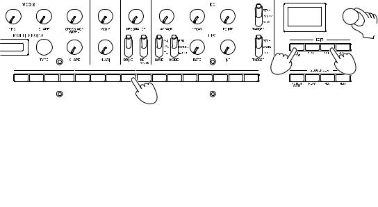
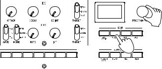
1.Press the EDIT MODE button.
The minilogue xd will enter Edit mode, and the display will look like the illustration shown below.
2.Turn the PROGRAM/VALUE knob, and select “GLOBAL EDIT.”
The minilogue xd will enter GLOBAL Edit mode.
Tip: GLOBAL EDIT can also be selected by pressing the EDIT MODE button.
3.Press button 8 three times.
“Auto Power Off” will be displayed.
4.Turn the PROGRAM/VALUE knob, and select “Off”.
5.Press the EXIT button.
The minilogue xd will enter Play mode, and the display will indicate the current program.
8
Playing the minilogue xd
Selecting and playing a program
The minilogue xd features 500 program memories. When the unit is shipped from the factory, preset programs are assigned to program numbers 1–200. Programs 201–500 contain init programs (programs that have been initialized).


 2
2
1 Make sure this button is unlit.
1.Check that the minilogue xd is in Play mode.
In Play mode, verify that the EDIT MODE button on the front panel is unlit. If the EDIT MODE button is lit, press the EXIT button.
2.Turn the PROGRAM/VALUE knob to select a program.
The display will indicate the program name. For details, refer to “Program list” (p.55).
Tip: In addition to showing the program name, the display can also be used as an oscilloscope to show the waveform created by the electrical signals of the sound.
3.Play the keyboard and try using the joystick and OCTAVE switch and other controls on the front panel.
You can use the OCTAVE switch to transpose the playing area of the keyboard by ±2 octaves.
The joystick mainly controls the pitch when moved from left to right, and changes parameters such as the cutoff frequency and vibrato depth when moved up and down. You can also change which parameters are controlled by the joystick. See “Button 4 (JOYSTICK)” (p.32) for details.
Use the VOICE MODE TYPE switch to switch between voice modes. Select a voice mode and play. To learn more about voice modes, see “VOICE MODE section” (p.15).
9
Using Favorites
You can use the favorites to register up to 16 programs that you like, to easily call them back later.
Recalling your favorite programs
1.In Play mode, press one of the buttons from 1–16 while holding down the SHIFT button.
The favorite program previously registered to that button will be recalled, and the program name will be shown in the display.
1
1 |
2 |
3 |
4 |
5 |
6 |
7 |
8 |
9 |
10 |
11 |
12 |
13 |
14 |
15 |
16 |
1
Registering your favorite programs
1.In Play mode, turn the PROGRAM/VALUE knob to select the program you like.
The display will indicate the program name.


 1
1
2
1 |
2 |
3 |
4 |
5 |
6 |
7 |
8 |
9 |
10 |
11 |
12 |
13 |
14 |
15 |
16 |
2
2.Hold down one of the buttons from 1–16 while keeping the SHIFT button pressed.
The program will be registered as a favorite program, and “Registered to Favorite” will be shown in the display.
Tip: The favorite programs that you register will be saved in the global settings.
10
Playing the sequencer
Each program in the minilogue xd includes sequence data. In this section, we’ll play the sequence data saved as part of the preset programs.
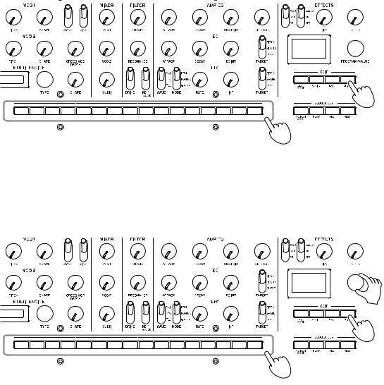
1. Turn the PROGRAM/VALUE knob to select a program.
The display will indicate the program name.
2.Press the PLAY button in the SE- QUENCER section.
The sequence data that is recorded in the current program will begin playing. The 1–16 buttons will light up to show
the current step while the sequencer is playing.


 1
1
2, 3
Tip: The sequencer tempo is set individually in each program. You can change the tempo in SEQ EDIT mode, “BPM” (p.37). You can also adjust the tempo from 56.0 to 240.0 BPM (beats per minute) by turning the TEMPO knob.
3. Press the PLAY button once more to end the Sequencer playback.
11
Programs
Program architecture
A program includes settings for sounds, voice mode and effects, as well as sequence data and so on. (MASTER knob and joystick settings are not included in programs.)
Try editing each related parameter, and enjoy the sounds of the minilogue xd.
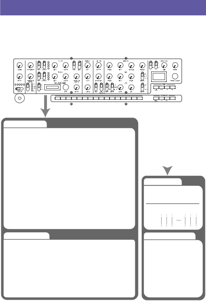
Basic parametres
MASTER |
Engine Parm Setting |
|
TEMPO |
(SHIFT + SHAPE) |
|
OCTAVE |
MIXER |
|
PORTAMENTO |
||
VCO1 Level |
||
VOICE MODE DEPTH |
||
VCO2 Level |
||
VOICE MODE Type |
||
MULTI Level |
||
VCO 1 |
||
VCF |
||
WAVE |
CUTOFF |
|
OCTAVE |
||
RESONANCE |
||
PITCH |
||
DRIVE |
||
SHAPE |
||
KEYTRACK |
||
|
||
VCO 2 |
AMP EG |
|
WAVEOCTAVE |
ATTACK |
|
PITCH |
||
DECAY |
||
SHAPE |
||
SUSTAIN |
||
SYNC |
||
RELEASE |
||
RING |
||
EG |
||
CROSS MOD DEPTH |
||
MULTI ENGINE |
ATTACK |
|
DECAY |
||
TYPE |
EG INT |
|
NOISE/VPM/USR |
||
TARGET |
||
SHAPE |
||
|
Detail parametres *
JOYSTICK |
PITCH SETTING |
|
X+ Bend Range |
Microtuning |
|
X- Bend Range |
Scale Key |
|
Y+ Assign |
Program Tuning |
|
Y+ Range |
Transpose |
|
Y- Assign |
LFO |
|
Y- Range |
||
LFO Target Osc |
||
CV INPUT |
||
LFO Key Sync |
||
CV IN Mode |
LFO Voice Sync |
|
CV IN1 Assign |
MODULATION |
|
CV IN1 Range |
||
EG Velocity |
||
CV IN2 Assign |
||
Amp Velocity |
||
CV IN2 Range |
||
|
||
* Edit mode parameters |
|
LFO |
|
|
|
|
|
|
|
|
WAVE |
|
|
|
|
|
|
|
|
MODE |
|
|
|
|
|
|
|
|
RATE |
|
|
|
|
|
|
|
|
INT |
|
|
|
|
|
|
|
|
TARGET |
|
|
|
|
|
|
|
|
MOD |
|
|
|
|
|
|
|
|
O‚/On |
|
|
|
|
|
|
|
|
MOD FX Type |
|
|
|
|
|
|
|
|
Sub Type (SHIFT + TypeSELECT) |
|
|
|
|
|
|
|
|
DELAY |
|
|
|
|
|
|
|
|
O‚/On |
Sequence data |
|
|
|||||
DELAY Sub Type |
|
|
||||||
|
|
|
|
|
|
|
|
|
TIME |
NOTE [STEP 1‹16] |
|
|
|
||||
DEPTH |
GATE TIME [STEP 1‹16] |
|
|
|||||
Wet/Dry (SHIFT + DEPTH) |
|
|
|
|
|
|
|
|
REVERB |
|
|
|
|
|
|
|
|
O‚/On |
STEP |
1 |
2 |
|
3 |
14 |
15 16 |
|
REVERB Sub Type |
|
|||||||
|
|
|
|
|
||||
TIME |
NOTE |
|
||||||
DEPTH |
|
|||||||
GATE |
|
|||||||
Wet/Dry (SHIFT + DEPTH) |
|
|||||||
|
Sequence parameters * |
|||||||
OTHER SETTINGS |
BPM (TEMPO) |
|
|
|
|
|
|
|
Multi Octave |
|
|
|
|
|
|
|
|
Multi Routing |
Step Length |
|
|
|
|
|
|
|
EG Legato |
Step Resolution |
|
|
|
||||
Portamento Mode |
Swing |
|
|
|
|
|
|
|
Portamento BPM |
Default Gate Time |
|
|
|
||||
Program Level |
|
|
|
|
|
|
|
|
MULTI ENGINE |
Motion Type (1‹4) |
|
Motion Enable (1‹4) |
||
Parameter 1-6 |
||
Motion Smooth (1‹4) |
||
PROGRAM NAME |
||
|
||
Program Name |
|
12
Creating sounds
You can edit the parameters that make up a program, in order to modify the sound as you like. There are two ways to create sounds on the minilogue xd.
•You can select an existing program that’s close to the sound you want, and edit that program’s parameters to achieve your own custom sound.
•You can also create your own sound from scratch from an init program.
Editing an existing program
1.In Program mode, select the program that you want to use as a starting point.
2.Use the knobs and switches on the front panel.
Take a moment to consider the differences between the current program and the sound you have in mind, and use the front panel controls to edit the necessary parameters.
Tip: For details on how the pitch, sound, and volume change when using the knobs and switches, refer to “Basic parameters” (p.15).
 We recommend that you save the program on the minilogue xd after editing the sound. Any edits that you make will be lost if you turn off the power or recall a different program. See “Saving a program” (p.14) for details.
Creating a program from scratch
To create a program from scratch, we recommend that you use the panel load function. This will load the current settings of each front panel control and provide a simple starting point for your sonic creations.
As you explore the front panel controls, you can see how each parameter will affect the sound, making it easier to understand how each section of the minilogue xd functions and how the parameters interact.
You can also create programs after initializing them (p.37 “Initialize Program”).
Panel load function
When the PLAY button is pressed while holding down the SHIFT button, the panel load function will be enabled. The sound will change to reflect the panel settings, and “Load Panel” will be indicated in the display.
13
Saving a program
We recommend that you save your program on the minilogue xd after editing the sound to your liking.
 Any edits that you make will be lost if you turn off the power or recall a different program before saving the program.
1.Edit the program in Play mode.
See “Basic parameters” (p.15) for details.
2.Press the WRITE button. The minilogue xd will enter write standby mode, and the WRITE button will blink.
The display will indicate the message “Where to write?”.
3. Turn the PROGRAM/VALUE knob to |
3 |
|
|
select the program number where your |
|
new sound will be saved. |
2, 4 |
Tip: Press the EXIT button to cancel the operation.
4.Press the WRITE button once more.
The display will indicate the message “Complete”.
 Never turn off the power while programs are being saved. Doing so may destroy the internal data.
14
Basic parameters
In this section, we’ll explain the basic parameters that make up a program.
The basic parameters are assigned to the knobs and switches on the front panel.
MASTER controls
To learn more about the OCTAVE button, see “Selecting and playing a program” (p.9).
TEMPO knob |
[BPM 56.0...240.0] |
Use this parameter to adjust the tempo of the sequencer for each program in beats per minute (BPM). When the voice mode is “ARP”, the value set here is also used for the arpeggiator tempo.
PORTAMENTO knob |
[0...127] |
This parameter controls the portamento time.
The further the knob is turned to the right, the longer the portamento time will be.
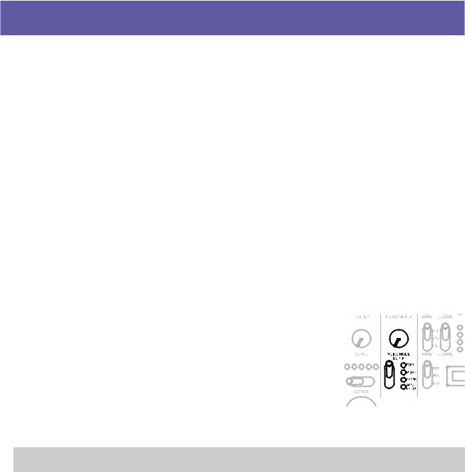
VOICE MODE section
The minilogue xd features four analog synthesizer voices. By changing the Voice mode, you can combine and allocate the voices in different ways.
There are four voice modes. Use the VOICE MODE TYPE switch to select a voice mode.
Turning the VOICE MODE DEPTH knob adds different effects for each Voice mode.
Voice mode list
Type |
Action |
VOICE MODE DEPTH knob effect |
|
|
|
POLY |
Used for basic playing as a |
[POLY, DUO 0...1023] |
|
4-voice polyphonic synth. |
Turn the knob to the right to switch to DUO |
|
|
mode, which stacks two voices when play- |
|
|
ing a key. Turning the knob to the right will |
|
|
increase the sound of the stacked voice, and |
|
|
deepen the detune effect. |
|
|
|
UNISON |
The 4 voices will be stacked |
[Detune 0C...50C] |
|
together into a single voice in |
Turning the knob to the right will increase the |
|
unison, as a mono synth. |
detuning effect. |
|
|
|
CHORD |
The voices will play as a chord. |
[Mono, 5th, sus2, m, Maj, sus4, m7, 7, 7sus4, |
|
|
Maj7, aug, dim, m7 5, mMaj7, Maj7 5] |
|
|
Selects either mono or the chord type. |
15
Type |
Action |
VOICE MODE DEPTH knob effect |
|
|
|
ARP/LATCH |
Uses the arpeggiator to play up |
[MANUAL 1, MANUAL 2, RISE 1, RISE 2, FALL 1, |
|
to 4 voices. |
FALL 2, RISE FALL 1, RISE FALL 2, POLY 1, POLY 2, |
|
Switches between LATCH ON |
RANDOM 1, RANDOM 2, RANDOM 3] |
|
and OFF. |
Selects the arpeggiator type. |
|
Set the arpeggiator tempo, swing |
If you set the VOICE MODE TYPE switch |
|
and gate time using the “TEMPO |
to ARP/LATCH and then move the switch |
|
knob” (p.15), “Swing” (p.37) |
down, the latch will be turned on (the LED |
|
and “Default Gate Time” |
will blink), and the arpeggiator will keep |
|
(p.37) settings. |
playing even after you take your hands off |
|
|
the keyboard. If you move the switch up |
|
|
while latched, the switch will latch off (the |
|
|
LED will light). |
|
|
|
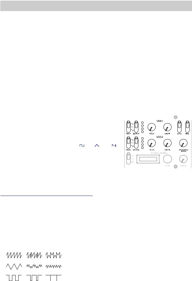
VCO 1/VCO 2/MULTI ENGINE section
VCO 1, VCO 2 VCO: Voltage Controlled Oscillator
There are two oscillators in the minilogue xd. Here, we will adjust the basic settings for the sound, including pitch (OCTAVE, PITCH), waveform (WAVE, SHAPE) and so on.
WAVE switch |
[SQR , TRI , SAW ] |
This sets the waveforms for oscillators 1 and 2. |
|
SQR (square wave): This waveform is used for electronic and wind instrument sounds.
TRI (triangle wave): This waveform has a rounder feel than the sawtooth or square wave.
SAW (sawtooth wave): This waveform is used to create sounds typical of analog synthesizers, such as synth basses and synth brass.
OCTAVE switch [16’, 8’, 4’, 2’]
The pitch of oscillators 1 and 2 can be set in octave steps.
PITCH knob |
[–1200...+1200] |
The pitch, or tuning, of oscillators 1 and 2 can be set in one-cent steps.
SHAPE knob |
[0...1023] |
This knob will determine the final shape, complexity, or duty-cycle (square) of the selected waveform for oscillators 1 and 2.
0  1023
1023
16
SYNC switch |
[OFF/ON] |
This switch lets you sync the oscillators.
Oscillator sync is a popular effect for creating edgy synth leads.
ON (up position): With this type of modulation, the phase of oscillator 2 is forcibly synchronized to the phase of oscillator 1. This adds harmonic overtones to the frequency of oscillator 2, making a complex waveform.
VCO 1 Wave
Sync
VCO 2 Wave (original)
VCO 2 Wave (output)
RING switch |
[OFF/ON] |
This lets you achieve a ring modulation effect.
Adjust the pitch of oscillator 2 to create non-tonal and metallic sounds.
ON (up position): Oscillator 1 is used to ring modulate oscillator 2.
VCO 1
VCO 2 
 RING MOD
CROSS MOD DEPTH knob |
[0...1023] |
Cross Mod (Modulation) allows oscillator 1 to modulate the pitch of oscillator 2. Turning the knob to the right results in stronger modulation.
MULTI ENGINE
The MULTI ENGINE is a digital sound generation engine.
This engine operates as a noise generator, a VPM oscillator or a user oscillator, to make a wide range of sounds not possible with analog oscillators. You can load your own oscillator programs into the user oscillator to make sounds.
NOISE/VPM/USR switch |
[NOISE , VPM , USR] |
This sets which engine will be used, the noise generator, VPM oscillator or user oscillator.
NOISE: The MULTI ENGINE is used as a noise generator. VPM: The MULTI ENGINE is used as a VPM oscillator. USR: The MULTI ENGINE is used as a user oscillator.
The TYPE knob and SHAPE knob work differently, depending on the NOISE/VPM/USER switch setting. The settings are explained below.
17

NOISE
Noise is used to create percussion instrument sounds, or sound effects such as surf.
Select one of the four noise generators using the TYPE knob. Move the SHAPE knob to make changes in the sound.
TYPE knob |
[High/Low/Peak/Decim] |
Select the noise generator to use.
The noise generator name will be indicated on the MULTI ENGINE display.
High: A high-pass filter will be used. Low: A low-pass filter will be used.
Peak: A peak filter (bandpass filter) will be used. Decim: A decimator will be used.
SHAPE knob
Set the noise generator parameter to make changes to the sound.
The parameters differ depending on the noise generator that you select using the TYPE knob, with the following effects.
SHAPE knob effects
Type |
Parameter |
Effect |
|
|
|
High |
CUTOFF |
[10.0Hz...21.0kHz] |
|
(SHAPE knob) |
Adjusts the cutoff frequency of the HPF. |
|
|
|
Low |
CUTOFF |
[10.0Hz...21.0kHz] |
|
(SHAPE knob) |
Adjusts the cutoff frequency of the LPF. |
|
|
|
Peak |
BANDWIDTH |
[110.0Hz...880.0Hz] |
|
(SHAPE knob) |
Adjusts the peak characteristic bandwidth. |
|
|
|
Decim |
RATE |
[240Hz...48.0kHz] |
|
(SHAPE knob) |
Adjusts the sample rate. |
|
|
|
|
KEY TRACK |
[0.0%...100.0%] |
|
(SHIFT button+SHAPE knob) |
Adjusts the depth of the sample rate via keyboard |
|
|
tracking. |
18
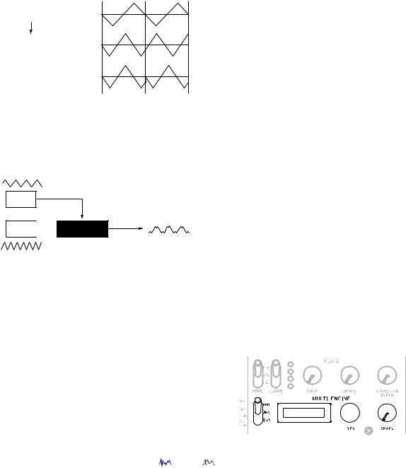
VPM
This engine is a VPM (Variable Phase Modulation) oscillator. The engine features a simple structure with one carrier and one modulator, but allows you to create a wide range of sounds.
Sixteen oscillator types are available for this VPM oscillator.
mod attack |
|
mod decay |
pitch |
shape mod int. pitch ratio |
eg
mod. depth (index)
phase mod |
phase carrier |
drive |
output |
|
|
||
feedback |
noise depth |
|
|
|
|
|
noise
TYPE knob |
[Sin1...Throat] |
This selects the oscillator type to use.
The name of the oscillator type will be indicated on the MULTI ENGINE display.
Tip: For the last four types after Decay1, setting Shape Mod Int to “–100%” will disable completely the effect of the EG.
Sin1: A basic oscillator type, using a sine wave for both the carrier and modulator. Sin2: Sine wave carrier and a modulator with self-feedback.
Sin3: Sine wave carrier with a 3x harmonics modulator. Sin4: Sine wave carrier with 5x harmonics modulator. Saw1: Modulated sawtooth carrier basic type.
Saw2: Carrier using a sine wave to simulate a sawtooth. Squ1: Square wave carrier type.
Squ2: Carrier using a sine wave to simulate a square wave.
Fat1: 1/4 subharmonic modulator with self-feedback and driven carrier output, emphasizing the lower harmonics.
Fat2: 3/4 subharmonic modulator with self-feedback and driven carrier output, emphasizing the lower harmonics.
Air1: Noise-modulated sine wave carrier.
Air2: Sine wave carrier modulated by both noise and a sine wave. Decay1: Type with decaying modulation amount.
Tip: You can edit the relative offsets of the internal EG decay time of the VPM (see block diagram) by using the parameters in PROGRAM EDIT mode “Button 10 (MULTI ENGINE)” (p.36).
Decay2: Type with strong decaying modulation amount.
Creep, Throat: Experimental, somewhat atonal type with complex and evolving modulations.
19
Loading...