


IMPORTANT SAFETY INSTRUCTIONS
•Read these instructions.
•Keep these instructions.
•Heed all warnings.
•Follow all instructions.
•Do not use this apparatus near water.
•Mains powered apparatus shall not be exposed to dripping or splashing and that no objects filled with liquids, such as vases, shall be placed on the apparatus.
•Clean only with dry cloth.
•Do not block any ventilation openings, install in accordance with the manufacturer’s instructions.
•Do not install near any heat sources such as radiators, heat registers, stoves, or other apparatus (including amplifiers) that produce heat.
•Do not defeat the safety purpose of the polarized or groundingtype plug. A polarized plug has two blades with one wider than the other. A grounding type plug has two blades and a third grounding prong. The wide blade or the third prong are provided for your safety. If the provided plug does not fit into your outlet, consult an electrician for replacement of the obsolete outlet. (for U.S.A. and Canada)
•Protect the power cord from being walked on or pinched particularly at plugs, convenience receptacles, and the point where they exit from the apparatus.
•Only use attachments/accessories specified by the manufacturer.
•Unplug this apparatus during lightning storms or when unused for long periods of time.
•Refer all servicing to qualified service personnel. Servicing is required when the apparatus has been damaged in any way, such as power-supply cord or plug is damaged, liquid has been spilled or objects have fallen into the apparatus, the apparatus has been exposed to rain or moisture, does not operate normally, or has been dropped.
•Do not install this equipment on the far position from wall outlet and/or convenience receptacle.
•Do not install this equipment in a confined space such as a box for the conveyance or similar unit.
•Use only with the cart, stand, tripod, bracket, or table specified by the manufacturer, or sold with the apparatus. When a cart is used, use caution when moving the cart/apparatus combination to avoid injury from tip-over.
The lightning flash with arrowhead symbol within an equilateral triangle, is intended to alert the user to the presence of uninsulated “dangerous voltage” within the product’s enclosure that may be of sufficient magnitude to constitute a risk of electric shock to persons.
The exclamation point within an equilateral triangle is intended to alert the user to the presence of important operating and maintenance (servicing) instructions in the literature accompanying the product.
THE FCC REGULATION WARNING (for U.S.A.)
This equipment has been tested and found to comply with the limits for a Class B digital device, pursuant to Part 15 of the FCC Rules. These limits are designed to provide reasonable protection against harmful interference in a residential installation. This equipment generates, uses, and can radiate radio frequency energy and, if not installed and used in accordance with the instructions, may cause harmful interference to radio communications. However, there is no guarantee that interference will not occur in a particular installation. If this equipment does cause harmful interference to radio or television reception, which can be determined by turning the equipment off and on, the user is encouraged to try to correct the interference by one or more of the following measures:
•Reorient or relocate the receiving antenna.
•Increase the separation between the equipment and receiver.
•Connect the equipment into an outlet on a circuit different from that to which the receiver is connected.
•Consult the dealer or an experienced radio/TV technician for help.
Unauthorized changes or modification to this system can void the user’s authority to operate this equipment.
CE mark for European Harmonized Standards
CE mark which is attached to our company’s products of AC mains operated apparatus until December 31, 1996 means it conforms to EMC Directive (89/336/EEC) and CE mark Directive (93/68/EEC). And, CE mark which is attached after January 1, 1997 means it conforms to EMC Directive (89/336/EEC), CE mark Directive (93/ 68/EEC) and Low Voltage Directive (73/23/EEC).
Also, CE mark which is attached to our company’s products of Battery operated apparatus means it conforms to EMC Directive (89/336/EEC) and CE mark Directive (93/68/EEC).
ii
 Handling of the internal hard disk
Do not apply physical shock to this device. In particular, you must never move this device or apply physical shock while the power is turned on. This can cause part or all of the data on disk to be lost, or may damage the hard disk or interior components.
When this device is moved to a location where the temperature is radically different, water droplets may condense on the hard disk. If the device is used in this condition, it may malfunction, so please allow several hours to pass before operating the device.
Do not turn the power on and off repeatedly. This may damage the D1600mkII.
This device begins to access the hard disk immediately after the power is turned on.
Never turn off the power while the HDD access indicator is lit or blinking. Doing so can cause all or part of the data on hard disk to be lost, or may cause malfunctions such as hard disk damage.
If the hard disk has been damaged due to incorrect operation, power failure, or accidental interruption of the power supply, a fee may be charged for replacement even if this device is still within its warranty period.
Phantom Power
To prevent hazard or damage, ensure that only microphone cables and microphones designed to IEC-268-15A are connected.
Data handling
Incorrect operation or malfunction may cause the contents of memory to be lost, so we recommend that you save important data on a CD or other media. Please be aware that Korg will accept no responsibility for any damages which may result from loss of data.
COPYRIGHT WARNING
This professional device is intended only for use with works for which you yourself own the copyright, for which you have received permission from the copyright holder to publicly perform, record, broadcast, sell, and duplicate, or in connection with activities which constitute “fair use” under copyright law. If you are not the copyright holder, have not received permission from the copyright holder, or have not engaged in fair use of the works, you may be violating copyright law, and may be liable for damages and penalties. If you are unsure about your rights to a work, please consult a copyright attorney. KORG TAKES NO
RESPONSIBILITY FOR ANY INFRINGEMENT COMMITTED THROUGH USE OF KORG PRODUCTS.
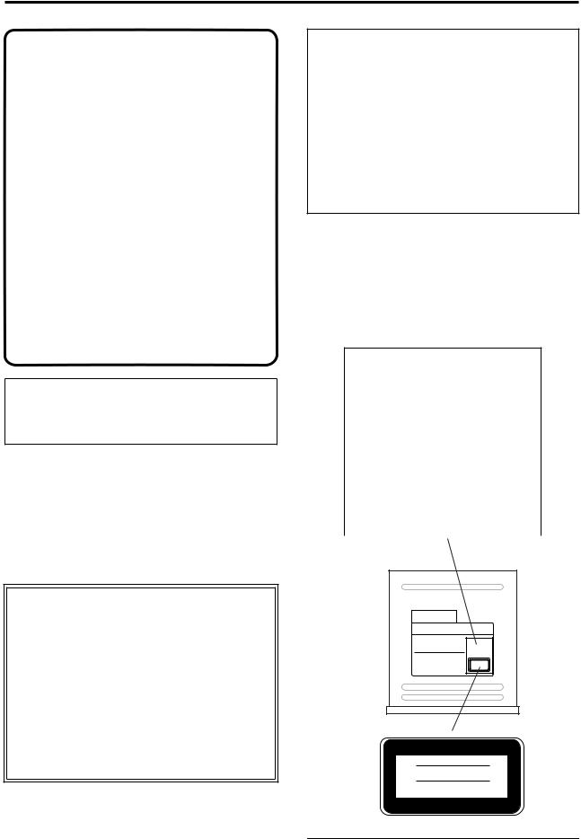
This product has been designed and manufactured according to FDA regulations “title 21. CFR. chapter 1, subchapter J. based on the radiation Control for Health and Safety Act of 1968,” and is classified as a class 1 laser product. There is no hazardous invisible laser radiation during operation because invisible laser radiation emitted inside of this product is completely confined in the protective housings.
The label required in this regulation is shown below.
CAUTION
Use of controls or adjustments or performance of procedures other than those specified herein may result in hazardous radiation exposure.
|
|
Optical pickup |
Type |
: SF-W35 |
|
Manufacturer |
: SANYO |
|
Laser output |
: |
Operation condition: 37.5mW; |
|
|
Maximum condition: 76.3mW |
Wavelength |
: |
783 +/-3nm |
|
|
|
DANGER
INVISIBLE LASER RADIATION WHEN OPEN.
AVOID DIRECT EXPOSURE TO BEAM.
VORSICHT
UNSICHTBARE LASERSTRAHLUNG,
WENN ABDECKUNG GEÖFFNET.
NICHT IN DEN STRAHL BLICKEN AUCH
NICHT MIT OPTISCHEN INSTRUMENTEN.
ADVARSEL
LASERSTRÅLING NÅR DEKSEL ÅPNES. STIRR IKKE INN I STARÅLEN.
ADVARSEL
LASERSTRÅLING VED ÅBNING. SE IKKE IND I STRÅLEN.
VARNING
LASERSTRÅLNING NÄR DENNA DEL ÄR ÖPPNAD.
STIRRA EJ IN I STRÅLEN.
VARO!
AVATTAESSA OLET ALTTIINA LASERSÄTEILYLLE.
ÄLÄ TUIJOTA SÄTEESEEN.
CLASS 1 LASER
CLASS 1 LASER
PRODUCT TO IEC
LASER KLASSE 1
NACH IEC 60825-1
*Company names, product names, and names of formats etc. are the trademarks or registered trademarks of their respective owners.
iii

Table of Contents
IMPORTANT SAFETY INSTRUCTIONS.................... |
ii |
|
THE FCC REGULATION WARNING (for U.S.A.)....ii |
||
CE mark for European Harmonized Standards.......... |
ii |
|
Data handling ............................................... |
iii |
|
Introduction......................... |
1 |
|
1. |
Main features............................................................... |
1 |
2. |
Printing conventions in this manual........................ |
2 |
3. |
Included items............................................................. |
2 |
Parts and their function ..................................... |
3 |
|
1. |
Top panel ..................................................................... |
3 |
2. |
Front panel................................................................... |
5 |
3. |
Rear panel .................................................................... |
6 |
Objects in the LCD screen and their functions .......... |
8 |
|
1. |
Objects in the LCD screen ......................................... |
8 |
2. |
Adjusting the LCD screen contrast .......................... |
8 |
Basic operation .............................................. |
9 |
|
1. |
Selecting a mode ......................................................... |
9 |
2. |
Selecting a tab page .................................................... |
9 |
3. |
Selecting and setting a parameter ............................ |
9 |
Preparations ................................................ |
10 |
|
1. |
Connections............................................................... |
10 |
2. |
Turning the power on/off....................................... |
11 |
Listening to the demo song .............................. |
12 |
|
Quick Start ......................... |
13 |
|
Step 1: Quick Recording .................................. |
13 |
|
1. |
Make connections ..................................................... |
13 |
2. |
Turn on the power.................................................... |
13 |
3. |
Create a new song .................................................... |
14 |
4. |
Rhythm....................................................................... |
14 |
5. |
Assign the input to a mixer channel ...................... |
15 |
6. |
Adjust the level ......................................................... |
15 |
7. |
Check the sound ....................................................... |
16 |
8. |
Record ........................................................................ |
16 |
9. |
Play back .................................................................... |
18 |
Step 2: Overdubbing....................................... |
19 |
|
1. |
Record a guitar.......................................................... |
19 |
2. |
Record a keyboard.................................................... |
20 |
3. |
Record vocals on virtual tracks .............................. |
22 |
4. |
Make insert effect settings....................................... |
24 |
Step 3: Mixdown ........................................... |
26 |
|
1. |
Apply effects ............................................................. |
26 |
2. |
Apply EQ (equalizer)............................................... |
27 |
3. |
Apply master effects ................................................ |
28 |
Step 4: Mastering .......................................... |
30 |
|
1. |
Apply an effect to the entire song .......................... |
30 |
2. |
Create the master track............................................ |
31 |
3. |
Write your song to a CD.......................................... |
32 |
Basic operation ................... |
35 |
|
Creating/selecting a song................................. |
35 |
|
1. |
Creating a new song ................................................ |
35 |
2. |
Naming a song.......................................................... |
35 |
3. |
Selecting another song............................................. |
36 |
Assign audio inputs to the mixer ........................ |
36 |
|
1. |
Analog inputs............................................................ |
36 |
2. |
Digital input .............................................................. |
38 |
3. |
Using the tuner ......................................................... |
39 |
Recording ................................................... |
39 |
|
1. |
Adjust the recording level, and record.................. |
39 |
2. |
Recording on virtual tracks..................................... |
40 |
3. |
Playback while recording addition tracks: |
|
|
Overdubbing ............................................................. |
40 |
4. |
Re-record part of a performance: Punch-in/out.. 40 |
|
5. |
Combining multiple tracks into two: Bounce ...... |
42 |
6. |
Other recording methods ........................................ |
43 |
Playback ..................................................... |
45 |
|
1. |
Playback..................................................................... |
45 |
2. |
Program play............................................................. |
45 |
3. |
Other playback options ........................................... |
45 |
Changing the time location ............................... |
46 |
|
1. |
Switching the counter display ................................ |
46 |
2. |
Moving the current time location .......................... |
46 |
3. |
Using scrub playback etc. to find a precise time |
|
|
location....................................................................... |
47 |
Using the mixer ............................................ |
48 |
|
1. |
Adjusting the volume .............................................. |
48 |
2. |
Adjusting the stereo position.................................. |
48 |
3. |
Using EQ to adjust the tone .................................... |
48 |
4. |
Pairing ........................................................................ |
49 |
5. |
Monitor settings........................................................ |
49 |
6. |
Solo settings............................................................... |
50 |
iv

7. |
Registering and playing scenes .............................. |
50 |
Using effects................................................ |
53 |
|
1. |
Overview of the effects ............................................ |
53 |
2. |
Insert effects............................................................... |
53 |
3. |
Master effects............................................................. |
55 |
4. |
Final effect.................................................................. |
56 |
5. |
Editing an effect ........................................................ |
56 |
6. |
Controlling an effect from an external device ...... |
57 |
7. |
Using an external effect............................................ |
58 |
Mixdown .................................................... |
58 |
|
1. |
Creating an audio CD .............................................. |
58 |
2. |
Recording to a master tape...................................... |
60 |
3. |
Using the sub inputs................................................. |
60 |
Track editing................................................ |
61 |
|
1. |
Track editing functions ............................................ |
61 |
2. |
Track editing examples ............................................ |
62 |
Song editing ................................................ |
69 |
|
1. |
Song editing operation............................................. |
69 |
2. |
Examples of song editing......................................... |
70 |
Rhythm/tempo settings ................................... |
71 |
|
1. |
Specifying and playing a rhythm ........................... |
71 |
2. |
Recording your performance while you listen to |
|
|
the rhythm ................................................................. |
72 |
3. |
Recording the rhythm .............................................. |
72 |
4. |
Specifying the tempo................................................ |
72 |
Data .......................................................... |
|
75 |
1. |
Backing up and restoring song data ...................... |
75 |
2. |
Backing up and restoring effect user data............. |
77 |
3. |
Saving a WAV file..................................................... |
79 |
4. |
Data compatibility with other models in the |
|
|
Digital Recording Studio series.................................. |
81 |
Drive |
......................................................... |
82 |
1. |
Checking the hard disk ............................................ |
82 |
2. |
Formatting the hard disk ......................................... |
82 |
3. |
Erasing the data from a CD-RW............................. |
83 |
4. |
Using the drive capacity efficiently........................ |
83 |
USB .......................................................... |
|
85 |
1. |
Saving data to your computer ................................ |
85 |
Updating the system ...................................... |
86 |
|
1. |
Downloading the system file .................................. |
86 |
2. |
Updating the system ................................................ |
86 |
MIDI.......................................................... |
|
87 |
1. |
MIDI connections...................................................... |
87 |
2. |
MIDI messages used by the D1600mkII ................ |
87 |
3. |
Using MIDI ................................................................ |
87 |
Reference .......................... |
91 |
1. COUNTER ................................................ |
91 |
Counter: Counter display............................................. |
91 |
2. SYSTEM/USB ............................................ |
91 |
P1 Control: Foot switch/control change device |
|
(pedal/MIDI) settings.............................................. |
91 |
P2 MIDI: MIDI settings ................................................. |
92 |
P3 Sync: Synchronization settings ............................... |
92 |
P4 MMC: MMC settings................................................ |
93 |
P5 B-U/Rst: Backup/restore using a removable disc93 |
|
P6 DiskUtil: Managing drives ...................................... |
96 |
3. RECORD .................................................. |
99 |
P1 RecMode: Selecting the recording mode............... |
99 |
P2 Bounce: Settings for bounce recording.................. |
99 |
4. TRACK ................................................... |
100 |
P1 Vtr1–8: Select virtual tracks 1–8............................ |
100 |
P2 Vtr9–16: Select virtual tracks 9–16........................ |
100 |
P3 EditTrk: Track editing............................................ |
100 |
P4 Import: Import a WAV file.................................... |
106 |
P5 Export: Export a WAV file..................................... |
107 |
5. SONG/CD ................................................ |
108 |
P1 SelSong: Selecting a song....................................... |
108 |
P2 EditSong: Song editing........................................... |
109 |
P3 PrgPlay: Program playback of songs................... |
110 |
P4 CDR/RW: Creating and playing CD-R/RW discs .. |
|
110 |
|
6. STORE ................................................... |
112 |
7. MARK .................................................... |
113 |
P1 Mark: Editing marks .............................................. |
113 |
8. SCENE ................................................... |
113 |
P1 ReadDel: Scene playback on/off and editing..... |
113 |
P2 MixView: Pan/fader scene display...................... |
114 |
9. TEMPO/RHYTHM....................................... |
115 |
P1 SetUp: Tempo and rhythm settings ..................... |
115 |
P2 TmpMap: Editing the tempo map........................ |
116 |
P3 TmpTrk: Create a tempo track.............................. |
117 |
10. IN/LOC1, OUT/LOC2, TO/LOC3, END/LOC4 ....... |
118 |
Locate functions ........................................................... |
118 |
11. AUTO PUNCH ......................................... |
119 |
P1 AtPunch: Settings for auto punch-in/out |
|
recording.................................................................. |
119 |
12. LOOP ................................................... |
120 |
P1 Loop: Loop playback/recording settings ........... |
120 |
v

13. UNDO................................................... |
120 |
14. TRIGGER............................................... |
121 |
P1 Trigger: Settings to start trigger recording ......... |
121 |
15. SCRUB ................................................. |
122 |
16. ENTER.................................................. |
122 |
17. INPUT/TUNER ......................................... |
123 |
P1 Ch1–8: Select the inputs for mixer channels 1–8 123 P2 Ch9–16: Select the inputs for mixer channels 9–16..
124 |
|
P3 InEq1–4: EQ settings for inputs 1–4 ..................... |
124 |
P4 InEq5–8: EQ settings for inputs 5–8 ..................... |
124 |
P5 Tuner: Tuner............................................................ |
124 |
18. EQ/PHASE ............................................. |
125 |
P1 Eq1–4: EQ settings for mixer channels 1–4 ......... |
125 |
P2 Eq5–8: EQ settings for mixer channels 5–8 ......... |
125 |
P3 Eq9–12: EQ settings for mixer channels 9–12 ..... |
125 |
P4 Eq13–16: EQ settings for mixer channels 13–16 . 125 |
|
P5 Phase: Phase settings for mixer channels............ |
125 |
19. INSERT EFFECT....................................... |
126 |
P1 InsAsn: Insert effect insertion location/type...... |
126 |
P2 InsEff1: Selection and settings for Insert Effect 1127 |
|
P3 InsEff2: Selection and settings for Insert Effect 2128 |
|
P4 InsEff3: Selection and settings for Insert Effect 3128 |
|
P5 InsEff4: Selection and settings for Insert Effect 4128 |
|
P6 Ins5–8: Selection and settings for Insert Effects 5– |
|
8 ................................................................................. |
128 |
20. MASTER EFFECT/AUX ............................... |
129 |
P1 MstEff1: Selection and settings for master effect 1 .. 129
P2 MstEff2: Selection and settings for master effect 2 ..
129 |
|
P3 EffSnd1: Send settings for effect 1........................ |
129 |
P4 EffSnd2: Send settings for effect 2........................ |
130 |
P5 AuxSend: External send settings.......................... |
130 |
P6 FinalEff: Selection and settings for the final effect... |
|
130 |
|
21. SOLO/MONITOR ...................................... |
131 |
P1 Solo: Solo select....................................................... |
131 |
P2 Monitor: Monitor settings ..................................... |
132 |
22. METER/TRACK VIEW ................................ |
133 |
23. TRACK STATUS ...................................... |
134 |
24. PAN .................................................... |
134 |
25. FADER................................................. |
134 |
26. TRANSPORT KEYS .................................. |
135 |
Effect Parameter List ........... |
137 |
Insert Effect (2in2outx2)/Master Effect/Final Effect . 137 |
|
Reverb RV1 – RV7 ....................................................... |
137 |
Delay DL1 – DL6 ......................................................... |
137 |
Modulation MO1– MO7 ............................................. |
139 |
Dynamics DY1 – DY7.................................................. |
140 |
Special Effect SE1 – SE4 .............................................. |
142 |
Insert Effect (2in2outx2)/ Final Effect ................. |
143 |
Large size LS1 – LS7.................................................... |
143 |
Insert Effect (1in2outx2) ................................ |
144 |
GT1 – GT6..................................................................... |
144 |
AS1 – AS3 ..................................................................... |
144 |
PA1 ................................................................................ |
145 |
EB1 – EB3 ...................................................................... |
145 |
MS1 ................................................................................ |
145 |
VO1 – VO2.................................................................... |
145 |
Effects within multi-effect programs GT1–VO2, and |
|
their parameters...................................................... |
145 |
Insert Effect (1in1outx4) ................................ |
148 |
Effects within multi-effect programs MM1–MM33, |
|
and their parameters.............................................. |
149 |
Insert Effect (1in1outx8) ................................ |
150 |
Effect Control ............................................. |
151 |
Appendices ....................... |
153 |
Troubleshooting .......................................... |
153 |
Various messages ....................................... |
157 |
About the hard disk and CD-R/RW drive.............. |
159 |
1. Hard disk ................................................................. |
159 |
2. About the CD-R/RW drive................................... |
160 |
3. Playing or recording from an audio CD ............. |
161 |
vi

Specifications ............................................. |
162 |
MIDI implementation chart.............................. |
164 |
Block diagram ............................................. |
165 |
Effect Program List ....................................... |
166 |
Rhythm Pattern List (215 patterns) .................... |
168 |
vii

viii
Introduction
Thank you for purchasing the Korg D1600mkII Digital
Recording Studio.
To ensure trouble-free enjoyment, please read this manual carefully and use the instrument as directed.
1. Main features
• 16-track digital recorder
The D1600mkII delivers studio-quality sound with 24-bit internal processing, 16/24-bit recording and playback, and uncompressed recording at a sampling frequency of 44.1 kHz. It allows a maximum of 16 tracks of simultaneous playback (16-bit) and up to 8 tracks of simultaneous recording. The recording time is a maximum of approximately 122 hours (16-bit, one track). Each track provides eight virtual tracks, meaning that you can record 128 tracks per song.
•XLR input jacks with +48V phantom power supply, analog inputs, dedicated guitar input jack, and digital jacks
All analog inputs of the D1600mkII use high-per- formance balanced head amps that take full advantage of its all-digital audio quality. The four XLR input jacks with +48V phantom power contain highquality mic preamps, allowing condenser mics to be connected directly. All phone jack inputs are balanced TRS-types. Unbalanced input is also supported. Levels from mic level to +16 dBu (higher than professional level) are supported, letting you directly connect a wide variety of audio sources. There’s also a dedicated guitar input jack. The S/P DIF digital input contains a sampling rate converter, allowing 48 kHz or 32 kHz sources to be automatically converted to 44.1 kHz for recording.
•Mixer section provides three-band EQ with sweepable mid-range
•100 scene memories, and mixer data transmission/ reception via MIDI
The D1600mkII’s 24-channel 8-bus mixer section provides 3-band EQ (high EQ and low EQ are shelving types, and mid EQ is a peaking type with adjustable center frequency) on every analog input and mixer channel. Since EQ is applied separately to the inputs and the mixer, you won’t have the problem of recording EQ settings being re-applied to the playback – a mistake that’s easy to make with MTR systems that have an analog internal mixer.
Mixer parameters such as fader, EQ, pan, and effect settings can be stored as a scene, and each song can contain one hundred scenes. Scenes can be switched automatically as time progresses, or can be easily recalled when desired as general-purpose settings. Mixer data such as fader and pan can be transmitted and received via MIDI, allowing the mixer to be automated from an external sequencer.
• Three independent effects usable simultaneously
The three independent built-in effects (Insert, Master, and Final) use 44-bit internal processing. For each of these three effects, you can choose an effect program that consists of up to five effects taken from 98 types of high-quality effect. 128 insert, 32 master, and 32 final effects (total 192) created by professional musicians and studio engineers are provided as preset programs. You can edit these preset effect programs and store 192 more of your own in the user area. External MIDI controllers or an expression pedal (EXP-2, XVP-10: sold separately) can control an insert effect in realtime.
• Sophisticated editing
The non-destructive editing offered only by digital recorders lets you edit without impairing the high audio quality. You can use auto or manual punch-in/ out. The Undo function that lets you revert to the state prior to a recording or editing operation, in conjunction with the Redo that cancels the Undo, lets you step back through as many as 99 prior recording or editing operations. Ten different track editing commands include the convenient Time Expansion/ Compression operation that lets you match phrases of differing tempo after they have been recorded, and Normalize that boosts low-level tracks to the appropriate level.
In each song you can assign 100 named Mark points and four Locate points, letting you move immediately to the song location where you want to edit.
•Hard disk drive built-in
•Hard disk USB drive and USB connector
The D1600mkII contains a high-capacity 40 GB hard disk drive. Of the total capacity, 2 GB are allocated as a “USB drive*” that can be connected to your computer via the USB connector for sharing of data, and the remaining capacity is used as a “song drive” for holding your songs. WAV files can be imported or exported, making it easy to transfer audio data to or from your computer.
*FAT 16 is supported
•Create audio CDs using the CD-R/RW drive
You can use the CD-R/RW drive to backup/restore songs and effect data, import/export WAV files, and create audio CDs. You can also insert an audio CD in the drive, patch the sound to a mixer channel, and record or play it.
An audio CD can be written in two ways; you can write one song at a time using Track At Once, or you can insert markers in a single song (e.g., recorded from a live performance) and write each section as a track of an audio CD by using the Disc At Once method.
Introduction |
|
|
|
|
|
Parts and their function |
|
|
|
|
|
in the LCD screen |
their functions |
Objects |
and |
|
|
|
|
Basic operation |
|
|
|
|
|
Preparations |
|
|
|
|
|
Listening to the demo song |
|
|
|
1
•Auto Save function automatically preserves your data at power-off
The D1600mkII features an Auto Save function that automatically saves your recorded or edited songs and phrases to the hard disk whenever you switch songs or turn off the power.
LCD screens
The parameter values shown in the LCD screens printed in this manual are explanatory examples, and may not necessarily match the displays that appear on your D1600mkII.
What is  ?
?
 (Resonant structure and Electronic circuit Modeling System) is Korg’s proprietary technology for digitally recreating the numerous factors that produce and influence a sound, ranging from the sound-pro- duction mechanisms of acoustic instruments and electric/electronic musical instruments, to the resonances of an instrument body or speaker cabinet, the sound field in which the instrument is played, the propagation route of the sound, the electrical and acoustic response of mics and speakers, and the changes produced by vacuum tubes and transistors.
2.Printing conventions in this manual
Switches and knobs [ ]
Keys, dials, and knobs on the panel of the D1600mkII are printed within [square brackets].
Parameters that appear in the LCD screen “ ”
Parameters that appear in the LCD screen are printed inside “double quotation marks.” The terms ‘button’ and ‘cell’ refer to objects in the LCD screen.
 The LCD screen of the D1600mkII is a touch panel. To select a parameter, simply touch that parameter directly. Alternatively, you can use the [CURSOR] keys to move the cursor to the desired parameter. Most of the procedure examples given in this manual will use the method of directly pressing the parameter in the LCD screen to select it.
Bold-face type
Panel settings such as for faders or the [TRACK STATUS] keys are printed in bold type, and parameter values are printed in “bold type.”
Bold type also indicates content within the text that we wish to emphasize.
Steps 1. 2. 3. …
Steps in a procedure are indicated as 1. 2. 3. …
p.■■
This indicates a page or parameter number for reference.
Symbols  ,
, 
These symbols respectively indicate points of caution and notes of advice.
[...] “xx” tab page
This indicates a page displayed in the LCD screen. To access this page, press the [...] key on the panel.
If there is more than one tab, the tab pages will be selected successively each time you press the [...] key.
3. Included items
Make sure that the following included items are all present.
•Owner’s manual (this document)
•Power cable
2
Parts and their function
1. Top panel
33 |
34 |
|
9 |
|
1 |
10 |
|
11 |
||
|
12~31
2 |
|
3 |
8 |
|
32 |
4 |
7 |
|
5 |
6 |
1LCD screen
The D1600mkII uses a TouchView system based on a touch panel screen. By pressing objects that are shown in the LCD screen, you can select pages, tabs, and parameters, and set their values.
Also displayed are the volume (level meters), time locations (locate) during recording or playback, and various other parameters.
2[TRACK STATUS] keys
These keys are used to put each track into playback, record, or to mute (silence) status. Each time you press a key, the track setting will alternate.
•Green: PLAY
•Orange: INPUT
•Red: REC
•Dark: MUTE
When recording from analog/digital input, you can arm up to eight recording tracks.
 These settings can be paired.
3[PAN] knobs (Ch1…16)
These knobs adjust the stereo location of each channel.
 These settings can be paired, and registered in a scene.
4[CHANNEL] faders (Ch1…16)
These faders adjust the recording/playback volume of each channel.
 These settings can be paired, and registered in a scene.
5[MASTER] fader
This adjusts the volume of all channels. During bounce recording, this sets the recording level of the bounce destination track.
6TRANSPORT keys
[REC] key, [RHSL] key, [PLAY] key, [STOP] key, [REW] key, [FF] key
These are used to perform recording operations such as playback and record.
7[VALUE] dial
This is used to modify parameter values, and to move the current time.
When the Scrub function is on, rotating the dial will cause the track to play at the corresponding speed.
8[CURSOR] key
This key moves the cursor.
Introduction |
|
|
|
|
|
|
|
|
|
|
|
|
Partsr and their tifunction |
|
|
|
|
|
|
|
|
|
|
in the LCD screen |
their functions |
||
Objects |
and |
||
|
|
|
|
|
|
|
|
Basic operation |
|
|
|
|
|
|
|
|
|
|
|
Preparations |
|
|
|
|
|
|
|
|
|
|
|
Listening to the demo song |
|
|
|
|
|
|
|
3
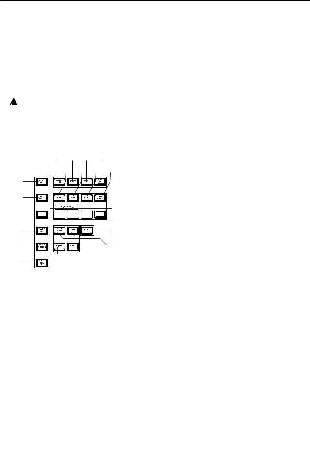
9[POWER] key
This turns the power of the D1600mkII on/off. When the D1600mkII is in standby mode, pressing the [POWER] key will turn on the power. If the D1600mkII is operating, pressing and holding the [POWER] key for a while will cause it to shut down and enter standby mode.
10HDD/CD access indicator
This indicator will light when the internal hard disk is being accessed for recording or playback, or when the internal CD-R/RW drive is operating.
 Never move the D1600mkII or apply physical shock to it when this HDD/CD access indicator is lit.
11MIDI indicator
This indicator will light when MIDI messages are received from the MIDI IN connector.
18 19 20 21
22 23 24 25
12
13
14 


 26
26
15 |
|
29 |
|
|
28 |
16 |
|
27 |
17 |
30 |
31 |
|
|
12[INPUT/TUNER] key
This key is used to select the mixer channel to which the audio signal from each input jack will be sent. This is also used when adjusting the EQ (for recording) that is applied to the analog inputs.
In addition, this key is used to access the tuner.
13[EQ/PHASE] key
This key is used to specify the EQ (for track playback) and phase of each channel.
 These settings can be paired, and registered in a scene.
14[INSERT EFFECT] key
This key is used to select the location of an insert effect, to select the effect type, and to select and edit effect programs.
 These settings can be registered in a scene.
15[MASTER EFFECT/AUX] key
This key is used to select and edit effect programs for master effects 1 and 2, and to set the send levels from each channel to the master effects. In addition, it is used to set the send amount to an external effect, and to select and edit effect programs for the final effects.
 These settings can be registered in a scene. The send settings can be paired.
16[SOLO/MONITOR] key
This key is used to solo an individual channel, send, or return. It is also used to select an audio source for monitoring.
When solo is on, the LED will blink.
17[METER/TRACK VIEW] key
This key is used to display volume data (level meters) during recording and playback, and to view audio event data in each track (track view).
18[SYSTEM/USB] key
This lets you make settings for the foot switch and MIDI functions, manage the disk drive, and backup/ restore data.
You can also connect the D1600mkII to your computer via the USB jack, and exchange data between your computer and the D1600mkII’s USB drive.
19[RECORD] key
Press this key to make recorder settings such as selecting the recording source or the bounce recording method etc.
20[TRACK] key
This key is used to select the virtual track for each track, to perform track editing operations such as copy or delete, and when importing or exporting WAV files.
21[SONG/CD] key
Press this key to create a new song, rename/select a song, perform a song editing operation such as copy or move, perform program playback of songs, or produce an audio CD (a CD-R/RW drive is required).
22[STORE] key
Press this key to register the time location for a locate point, a mark, or a scene.
23[MARK] key
This key registers the desired time location in a song as a Mark, so that the registered time can be recalled instantly.
It is also used to edit marks by renaming or deleting them etc.
24[SCENE] key
This key is used to register [CHANNEL] fader, [PAN] knob, EQ or effect send settings as a scene at the specified time location in a song. If the Scene Read setting is on during playback, the registered scenes will be selected automatically at the corresponding times. Scenes can also be sorted, renamed, or deleted.
This key will light when Scene Read is “On.”
25[TEMPO/RHYTHM] key
This key is used to set the tempo for a song, create a tempo map, and turn the rhythm function on/off. This key will light when the Rhythm function is on.
26[IN/LOC1] key, [OUT/LOC2] key, [TO/LOC3] key, [END/LOC4] key
These keys are used to register a desired time location within a song, or to instantly jump to a registered time location.
4
The time locations registered here are used as the punch-in/out locations, and the editing range for track editing operations such as copy or delete.
By holding down the [IN/LOC1] key and pressing the [OUT/LOC2] key, you can listen to the audio between the IN–OUT points.
27[AUTO PUNCH] key
This key is used to turn the Auto Punch-in/out function on/off, to set the pre/post roll time, and to verify the start/end locations.
This key will light when the Auto Punch-in/out function is on.
28[LOOP] key
This key is used to turn the Loop function on/off for playback or recording, and to verify the start/end locations.
This key will light when the Loop function is on.
29[UNDO] key
After recording or editing a track, you can use the Undo function to return the data to its prior state, and then (if desired) use the Redo function to cancel the Undo and go back to the edited data.
Up to 99 prior recording or editing operations can be undone. You can select from 1, 8, or 99 levels of undo. This key will light when Undo or Redo is available.
30[TRIGGER] key
This is the on/off key for the Trigger Recording function, which causes recording to begin automatically in response to an audio input. This key is also used to set the threshold level and pre-trigger time.
This key will light when the Trigger Recording function is on.
31[SCRUB] key
This key turns the Scrub, Play To/From, and Slow Play functions on/off. The key will light when the Scrub function is “On.” These functions are used by operating the [VALUE] dial or TRANSPORT keys.
32[ENTER] key
This key is used to finalize a parameter selection, or to turn a parameter on/off.
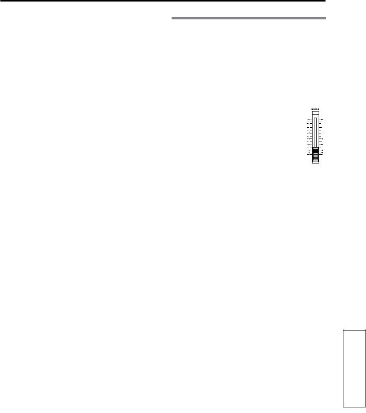
33[TRIM] knob: –60...–10...+4 dBu
These knobs adjust the input level. The markings indicate the input level.
The LEDs will show different colors to indicate the following statuses.
•Lit green: input present
•Lit orange: correct level
•Lit red: excessive level
Adjust each [TRIM] knob appropriately, so that the LEDs do not turn red when the connected instrument is played at maximum volume.
The input level will depend on the instrument or performance, but the approximate ranges are as follows.
•–60 – –40 dBu: mic input
•–30 dBu: guitar, bass guitar
•–10 dBu: consumer audio devices such as a CD player
•+4 dBu: keyboards or studio equipment
 If the [TRIM] knob is raised when nothing is connected to an input, hum or noise may result.
34[MONITOR OUT LEVEL] knob
This knob sets the volume level from the [MONITOR OUT L/R] jacks.
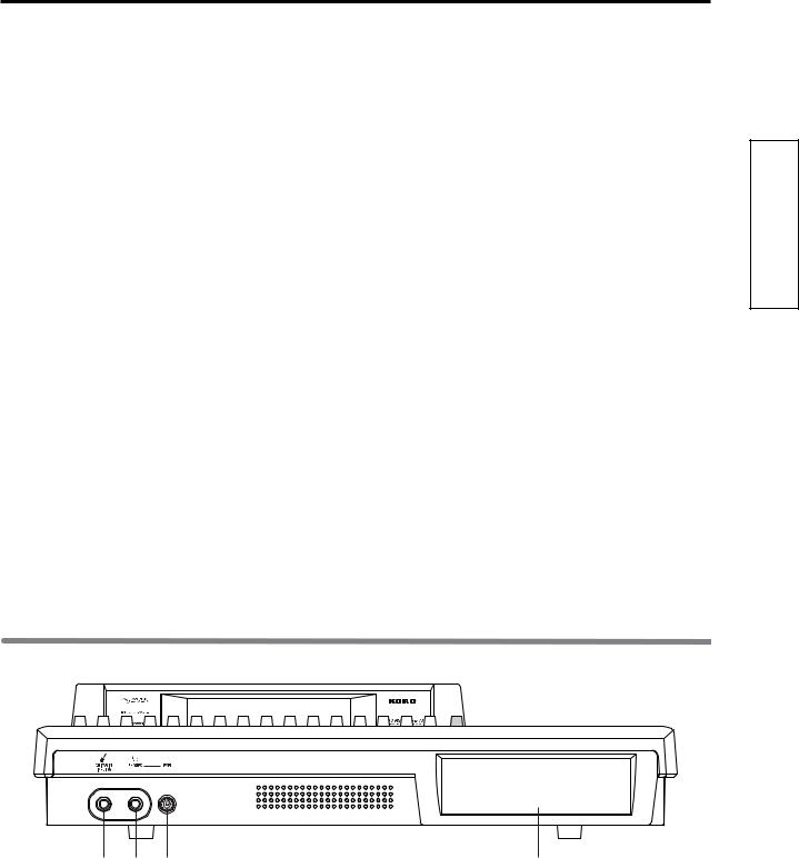
2. Front panel
|
1 |
2 |
3 |
4 |
1 |
[GUITAR IN] jack |
|
|
3 [PHONES LEVEL] knob: 0...10 |
|
A guitar or bass guitar can be plugged in here. |
This knob sets the volume level of the headphones. |
||
|
This is an unbalanced 1/4" (6.3 mm) input jack with |
The volume will increase in correspondence to the |
||
|
1 MΩ impedance. |
|
|
printed grid. |
2 |
[PHONES] jack |
|
|
4 CD-R/RW drive bay |
|
A set of headphones can be connected here. |
Use this to backup/restore data, and to play or write |
||
|
This is a 1/4" stereo phone jack. |
audio CDs. For details on handling and inserting a |
||
|
This outputs the same signal as the [MONITOR OUT |
disc, refer to “2. About the CD-R/RW drive” |
||
|
L/R] jacks. |
|
|
(→p.160). |
Introduction |
|
|
|
|
|
Partsr and their tifunction |
|
|
|
|
|
in the LCD screen |
their functions |
Objects |
and |
|
|
|
|
Basic operation |
|
|
|
|
|
Preparations |
|
|
|
|
|
Listening to the demo song |
|
|
|
5
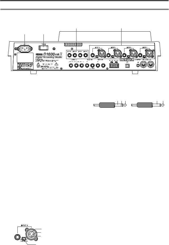
3. Rear panel
4 |
3 |
1 2
|
|
|
|
|
|
|
|
|
|
|
|
|
|
|
|
|
|
|
|
|
|
|
|
|
|
|
|
|
|
|
|
|
|
|
|
|
|
|
|
|
|
|
|
|
|
|
|
|
|
|
|
|
|
|
|
|
|
|
|
|
|
|
|
|
|
|
|
|
|
|
|
|
|
|
|
|
|
|
|
|
|
|
|
|
|
|
|
|
|
|
|
|
|
|
|
|
|
|
|
|
|
|
|
|
|
|
|
|
|
|
|
|
|
|
|
|
|
|
|
|
|
|
|
|
5 |
6 |
7 |
8 |
9 |
10 11 |
12 |
13 14 |
15 |
||||||||||||||||
1 [AC] connector
Connect the included power supply cable here.
2[Main power] switch
This turns the main power on/off.
When the [Main power] switch is turned on, the D1600mkII will be in standby mode. In standby mode, you can press the [POWER] key to turn on the power of the D1600mkII. While the D1600mkII is operating, you can use the [POWER] key to shut down, and then turn the main power off to turn the power off completely.
 To turn off the power, you must first press the [POWER] key to perform the shutdown operation. Never turn off the [Main power] switch or disconnect the power cable until shutdown has been completed.
If you turn off the [Main power] switch or disconnect the power cable before shutdown has been completed, data and user settings may be lost, or the hard disk may be damaged.
3[INPUT 1], [INPUT 2], [INPUT 3], [INPUT 4] jacks
Audio sources such as mic or line (keyboard etc.) can be connected here.
Both balanced XLR and balanced 1/4" TRS phone jacks are provided.
Unbalanced phone plugs can also be connected. +48V phantom power is provided on the XLR jacks so that you can use condenser mics.
 If you connect the phone jack, you will not be able to input from the XLR jack. If you want to use the XLR jack, don’t connect anything to the phone jack.
2: HOT 1: GND 3: COLD
Phantom power switch
Balanced phone plug |
Unbalanced phone plug |
|
|
GND COLD HOT |
GND HOT |
||
 If a condenser mic is connected or disconnected with the phantom power switch on, damage to your equipment may occur. For this reason, always turn the phantom power switch off before connecting a condenser mic.
 Never connect an unbalanced mic or device when the phantom power switch is on. Doing so may damage your equipment.
4[INPUT 5], [INPUT 6], [INPUT 7], [INPUT 8] jacks
Mic/line (e.g., keyboard) sources can be input here. These are balanced 1/4" TRS phone jacks. Unbalanced phone jacks can also be connected.
 If you connect a plug to the [GUITAR IN] jack, no input signal will be received from the [INPUT 8] jack. If you wish to use the [INPUT 8] jack, disconnect the plug from the [GUITAR IN] jack.
5[FOOT SW] jack
When your hands are occupied with playing an instrument, you can use a foot switch to control basic operations of the D1600mkII recorder.
A foot switch can be used to start/stop the playback, start/end manual punch-in recording, register a mark, or to record tap tempo.
Connect the foot switch (optional PS-1) to this jack.
6[EXPRESSION PEDAL] jack
You can use a pedal to control a specified parameter of an insert effect. You can control the parameter in realtime while you play or record.
Connect an expression pedal (separately sold option, EXP-2, XVP-10 etc.) to this jack.
6

7[AUX OUT] jack
Connect this to the input jack of an external effect device.
This jack outputs the external send signal from each mixer channel. This is a 1/4" phone jack.
8[MONITOR OUT L/R] jacks
Connect your external monitor system to these jacks. The bus that is sent to the monitor output is selected in the [SOLO/MONITOR] “Monitor” tab page.
These jacks output the same audio signal as [PHONES].
This is a 1/4" phone jack.
9[MASTER OUT L/R] jacks
These are analog outputs for the master LR bus which combines the signals from each mixer channel, or for the audio source that is selected by the Solo function. The Solo selection is made in the [SOLO/MONITOR] “Solo” tab page.
Connect your external monitor system or recording device to these jacks. They output the same audio signal as the [S/P DIF OUT] jacks.
This is a 1/4" phone jack.
10[S/P DIF OUT] jack
This is an optical-type S/PDIF format (IEC60958, EIAJ CP-1201) digital output jack (stereo).
Use an optical cable to connect this jack to the optical digital input of your DAT or MD.
This jack digitally outputs the same audio signal as the [MASTER OUT L/R] jacks at a sampling rate of 44.1 kHz.
11[S/P DIF IN] jack
This is an optical-type S/PDIF format (IEC60958, EIAJ CP-1201) digital input jack (stereo).
Use an optical cable to connect this jack to the optical digital output of your DAT or MD.
A sampling rate converter is built in. If the connected source has a sampling rate of 48 kHz or 32 kHz source, it will be converted automatically to 44.1 kHz.
12[USB] connector
Use a USB cable to connect this to your computer.
 You cannot connect USB peripheral devices such as an external hard disk or CD-R/RW drive to the D1600mkII.
13[LCD CONTRAST] knob
This adjusts the contrast of the LCD screen. The optimal setting will depend on the viewing
angle, so adjust the contrast as necessary. Looking from the front panel, turning the knob toward the right will darken the text, and turning it toward the left will lighten the text.
14[MIDI OUT] connector
MIDI messages are transmitted from this connector. Use this when you wish to control a connected external MIDI device from the D1600mkII.
15[MIDI IN] connector
MIDI messages are received at this connector. Use this when you wish to control the D1600mkII from a connected external MIDI device.
Introduction |
|
|
|
|
|
Partsr and their tifunction |
|
|
|
|
|
in the LCD screen |
their functions |
Objects |
and |
|
|
|
|
Basic operation |
|
|
|
|
|
Preparations |
|
|
|
|
|
Listening to the demo song |
|
|
|
7
Objects in the LCD screen and their functions
1. Objects in the LCD screen
The LCD screen of the D1600mkII features the Touch View system, which uses a touch panel.
By pressing objects displayed in the LCD screen you can perform operations such as selecting pages, setting parameter values, moving the cursor location, or editing settings.
In this manual, terms enclosed in “quotation marks” such as “...”, “...” button, or “...” tab refer to objects in the LCD screen which you can operate. Terms enclosed in square brackets such as [...] key, [...] knob, [...] dial, or [...] fader refer to controls etc. located on the top panel, front panel, or rear panel.
a:Current parameter |
c: Popup |
d:Toggle |
||||||
display |
|
|
button |
|
button |
|||
|
|
|
||||||
|
|
|
|
|
|
|
|
|
|
|
|
|
|
|
|
|
|
|
|
|
|
|
|
|
|
|
|
|
|
|
|
|
|
|
|
|
|
|
|
|
|
|
|
|
|
|
|
|
|
|
|
|
|
e: Tab |
b: Edit cell |
a: Current parameter display
This is the name of the parameter currently selected by the edit cell.
For icon-type parameters such as EQ or fader, the value is displayed at the right.
b: Edit cell
When you select a parameter in the LCD screen, the parameter value will be highlighted in some cases. This area is referred to as the edit cell, and your editing will apply to the highlighted portion.
The parameter value in the edit cell can be modified using the [VALUE] dial or by using the popup buttons in the LCD screen.
c: Popup button
When you press this button, a dialog box (f) will appear. To enter a parameter value, choose the desired value from the dialog box.
 ,
,  ,
, 
d: Toggle button
Pressing this type of button will alternately switch a function between on/off.
 (on)/
(on)/ (off)
(off)
e: Tab page
Each mode contains numerous parameters, which are organized into pages. Each page is accessed by its own tab.
f: Dialog box
To execute, press the “OK” button. To cancel, press the “Cancel” button. The dialog box will close.
g: Radio buttons |
f: Dialog box |
g: Radio buttons
These buttons are used to select one of multiple items. Press one of the radio buttons.
h: Icons
These are objects shaped like faders or knobs. To modify a value, select it and rotate the [VALUE] dial.
h:Icons
i:Scroll buttons
These buttons are used to view parameter values that cannot be displayed in a single screen.
i: Scroll buttons
2. Adjusting the LCD screen contrast
Use the rear panel [LCD CONTRAST] knob to adjust the contrast.
8
Basic operation
1. Selecting a mode
To make settings in the LCD screen for the various functions of the D1600mkII, you must first press the key of the mode that includes that function.
For the functions of each mode, refer to “Reference” (→p.91–).
2. Selecting a tab page
Each mode contains numerous parameters, and these are organized into pages. Pages are accessed by tabs.
1.Press the key for the desired mode.
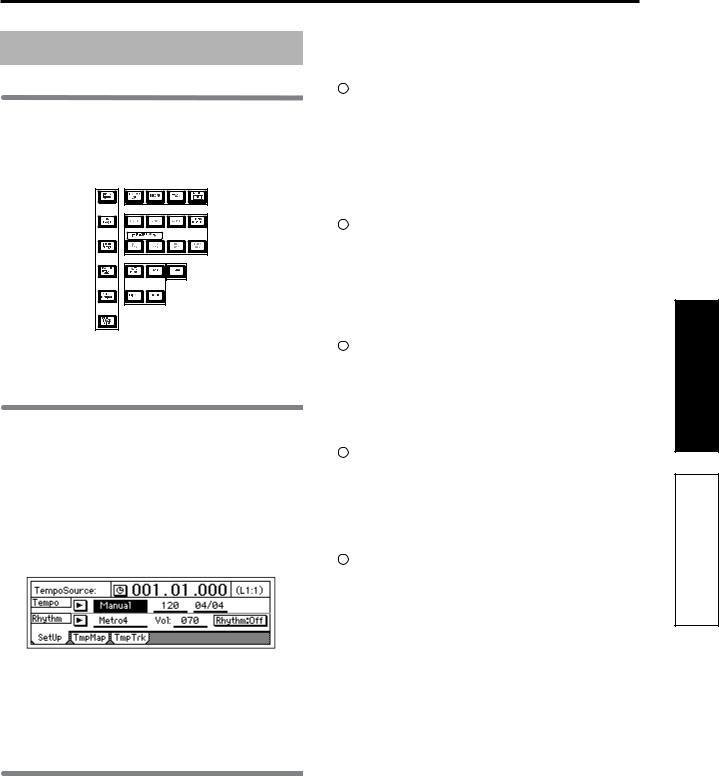
The illustration below shows a tab page of TEMPO/ RHYTHM mode that will appear when you press the [TEMPO/RHYTHM] key.
 In this manual, this is referred to as the [TEMPO/ RHYTHM] “SetUp” tab page.
2.Select the desired tab page.
Each time you press the key of the currently selected mode, you will cycle through the tab pages of that mode.
Some pages contain only one tab.
3.Selecting and setting a
parameter
Selecting a parameter
Use one of the following methods to select the parameter that you wish to edit.
•In the LCD screen, press that parameter directly.
•Press the up/down/left/right [CURSOR] keys to move the cursor to that parameter.
•In a list display screen, rotate the [VALUE] dial to move the cursor.
Setting a parameter value
The method of setting a parameter value will differ depending on the type of parameter.
Underlined “___” parameters, and icons such as EQ
Either directly press the parameter displayed in the LCD, or use the [CURSOR] keys to move the edit cell so that the parameter is highlighted, and rotate the [VALUE] dial to edit the value.
This is the typical method, and also applies for underlined parameters such as “Tempo”, parameters displayed as an icon such as EQ, and changes in locate times.
Popup buttons and dialog boxes
Use the popup button to access the dialog box, and set the parameter value.
•When you press a popup button shown in the LCD screen, a dialog box will appear.
•Use the [CURSOR] keys to move the edit cell to the popup button, and press the [ENTER] key to access the dialog box.
Toggle buttons
These buttons are used to turn a function on/off.
•Each time you press a toggle button shown in the LCD screen, the setting will alternate on/off.
•Use the [CURSOR] keys to select the parameter, and press the [ENTER] key. The button will turn on/off each time you press it.
Radio buttons
These buttons are used to select one of multiple choices.
•When you press one of the radio buttons shown in the LCD, it will be selected.
•Use the [CURSOR] keys to move the edit cell to the desired button, and press the [ENTER] key.
Selecting an item from a list
•To select a song or mark, rotate the [VALUE] dial to select the desired item.
•To select a song in a program play list, use the following procedure.
1.Select the playback list number.
2.Rotate the [VALUE] dial to select the song.
Introduction |
|
|
Parts and their function |
|
in the LCD screen their functions |
Objectsj and |
|
Basic operation |
|
|
Preparations |
|
|
Listening to the demo song |
|
9
Preparations
1. Connections
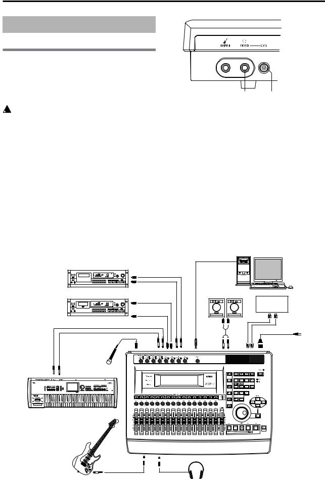
The diagram below shows a basic example of connections when using the D1600mkII to record. Make the appropriate connections for your system, substituting your own equipment as necessary for the equipment shown here.
 Be sure that the power is turned off while you are making connections. If the power is on while connections are being made, your speaker system may be damaged, or other malfunctions may occur.
1.Connect the included power supply cable.
Connect the power supply cable to the D1600mkII’s [AC] connector. Then plug the other end into an electrical outlet.
2.Connect your audio monitoring system.
Use a phone cable to connect powered monitors etc. to the [MONITOR OUT L/R] jacks.
If you will be monitoring through headphones, connect the 1/4" phone plug of your headphones to the [PHONES] jack.
Use the [PHONES LEVEL] knob to adjust the volume.
[PHONES] jack [PHONES LEVEL] knob
 The audio signal that is output from the [MONITOR OUT L/R] jacks and the [PHONES] jack is set in the [SOLO/MONITOR] “Monitor” tab page.
3.Connect your input devices. To record analog signals
•Guitar/bass ↔ [GUITAR IN] jack
•Mic (XLR) ↔ [INPUT 1]–[INPUT 4] jacks
•Synthesizers, etc. ↔ [INPUT 1]–[INPUT 8] jacks For details on specifying how the input audio signals are sent to mixer channels, and how to monitor the input sound, refer to “Assign audio inputs to the mixer” (→p.36).
 A guitar or bass guitar that is being sent through a compact effect device can be connected to [INPUT 1]–[INPUT 8].
|
|
|
|
Computer |
|
Master recorder (Analog: cassette tape recorder, etc.) |
|
|
|
||
INPUT L/R |
|
|
|
||
|
MASTER |
|
|
|
|
|
OUT L/R |
|
|
|
|
Master recorder (Digital: DAT, MD, etc.) |
|
Powered monitors etc. |
|
||
DIGITAL IN |
|
|
MIDI |
||
|
S/P DIF OUT |
|
|
||
|
|
|
sequencer |
||
DIGITAL OUT |
|
|
MIDI |
||
|
|
|
|
||
|
S/P DIF IN |
|
|
OUT/IN |
|
|
|
USB |
|
to the AC outlet |
|
INPUT |
INPUT |
MONITOR |
MIDI |
||
AC connector |
|||||
1–4 |
1–8 |
OUT L/R |
IN/OUT |
||
Mic
OUTPUT 
Keyboard |
GUITAR IN 
 PHONES
Guitar
Headphones
10
 When inputting in stereo, you should select two adjacent inputs (1–2, 3–4) so that track editing can be performed more efficiently.
 If you are recording from a connected mic, locate the mic at a sufficient distance from the D1600mkII so that it does not pick up noise.
Connections for recording digital sources
•Optical digital (S/P DIF) output of a digital output device such as DAT or MD ↔ [S/P DIF IN] jack of the D1600mkII (use an optical digital cable for connection)
For details on assigning the audio inputs to mixer channels and auditioning the input sound, refer to “Assign audio inputs to the mixer” (→p.36)
4.Make other connections.
Connections for mixdown
Here’s how to make connections when the song created on the D1600mkII will be mixed down on an external recording device (DAT, MD, tape recorder, etc.)
•Optical digital (S/P DIF) input of a digital recording device such as DAT or MD ↔ [S/P DIF OUT] of the D1600mkII
•AUX IN inputs of an analog recording device such as a cassette tape recorder ↔ [MASTER OUT L/R] jacks of the D1600mkII
Connections when using external effects
If you wish to apply an external effect to the signal from the [AUX OUT] send output, use the [INPUT 1]–[INPUT 8] jacks to receive the return signal(s).
In this case, you can choose whether the signal(s) will be returned to the mixer channel(s) in the same way as a conventional input, or sent directly to the master bus. Refer to “7. Using an external effect” (→p.58).
Connections when using a foot switch to perform manual punch recording, or playback/stop etc.
Connect the pedal switch (separately sold option: PS- 1) to the [FOOT SW] jack.
Connections when using a foot pedal to control effects
Connect the expression pedal (separately sold option: EXP-2, XVP-10) to the [EXPRESSION PEDAL] connector.
 If a volume pedal is connected, it will not operate correctly.
Connections when controlling effects or switching scenes from an external MIDI device
Connect the MIDI OUT connector of the external MIDI device ↔ [MIDI IN] connector of the D1600mkII.
Connections for synchronizing the D1600mkII with a MIDI sequencer
MIDI IN connector of your sequencer ↔ [MIDI OUT] connector of the D1600mkII (use a MIDI cable for connection)
MIDI OUT connector of your sequencer ↔ [MIDI IN] connector of the D1600mkII
Connections for saving or backing-up data on your computer
USB connector of your computer ↔ [USB] connector of the D1600mkII (use a USB cable for connection)
2. Turning the power on/off
Turning the power on
Use the following procedure to turn on the power of the D1600mkII and of the devices connected to it.
 Before turning the power on, be sure to lower the volume of each device to the minimum position, and turn the devices on beginning with the first device in the signal chain (i.e., devices that produce audio signals).
1. Lower the D1600mkII’s [MASTER] fader to the – ∞ position. Also turn down the vol-
ume of each connected device. 2. Turn on the power of the external input device, such as a keyboard connected to the D1600mkII. 3. Turn on the [Main power] of the
D1600mkII.
The STANDBY LED will light. The D1600mkII will be in “standby” mode.
4.Press the [POWER] key of the D1600mkII to turn on the power.
The opening message will appear in the LCD screen, and then the [SONG/CD] “SelSong” tab page will appear. The selected song will be the one that had been selected when the power was last turned off.
5.Turn on the power of your external equipment, such as the monitor system to which audio is being sent from the D1600mkII.
Turning the power off
When you are finished playing or recording a song, turn off the power. If you will not be using the D1600mkII for an extended time (e.g., when you have finished work for the day), be sure to turn off the main power so that the power is turned off completely. Use the following procedure to turn off the power of the D1600mkII and of the connected devices.
 Before turning off the power, turn the volume of all devices down to the minimum position, and turn off the power switches beginning with the devices that are at the end of the audio signal chain.
 When you wish to turn off the power, you must perform the shutdown operation. Never turn off the [Main power] switch or disconnect the power cable until the shutdown has been completed. If you turn off the main power or disconnect the power cable before shutdown is complete, data or user settings may be lost, or you may damage the hard disk.
 Audio that is recorded on the D1600mkII and the mixer settings you make are saved automatically when you select or switch songs, or when you shut down. However, effects that you edit will be lost unless you save them.
1.If you wish to keep any effect settings that you edited, save them. Refer to “5. Editing an effect” (→p.56).
2.Lower the [MASTER] fader of the D1600mkII to the
–∞ position. Lower the volume of any external devices to the minimum position.
Introduction |
|
|
|
|
|
Parts and their function |
|
|
|
|
|
in the LCD screen |
their functions |
Objects |
and |
|
|
|
|
Basic operation |
|
|
|
|
|
Preparations |
|
|
|
|
|
Listening to the demo song |
|
|
|
11

3.Turn off the power of the external output devices (such as your monitor system) to which audio is being sent from the D1600mkII.
4.Press and hold down the D1600mkII’s [POWER] key to shut it down.
When you press and hold the [POWER] key, a dialog box will ask you for confirmation. If you press the “Yes” button, the song will be saved automatically, and then the D1600mkII will shut down and enter standby mode. If you press the “No” button, you will return to the previous screen.
If you press the “Restart” button in the power-off confirmation dialog box, the D1600mkII will restart.
By restarting, you can delete the Undo data and recover the space it had occupied on the hard disk.
5.By pressing the D1600mkII [Main power] switch to turn it off, you can turn the power off completely.
6.If an external drive is connected, turn off the power of the external drive.
7.Turn off the power of external input devices, such as keyboards.
Listening to the demo song
Here’s how to listen to the demo songs.
1.Move the D1600mkII’s [CHANNEL] faders to the 0 mark, and the [MASTER] fader to the –∞ mark.
2.Press the [SONG/CD] key to access the “SelSong” tab page.
Make sure that “001: SISTER DANCE” is selected.
3.Make the [TRACK STATUS] key LED of all tracks light green (PLAY).
If any are lit a different color or are dark, press the key to make the LED light green.
4.Press the [PLAY] key to begin playback.
5.Slowly raise the [MASTER] fader to adjust the volume level.
6.When the demo song ends, press the [STOP] key to stop playback.
12
Quick Start
The Quick Start section consists of the following four steps.
We’ll begin our explanation by telling how to connect your equipment, and take you all the way through to the final step of writing your performance to CD-R. Please take some time to work through this Quick Start so that you can become familiar with the process of recording on the D1600mkII.
Step 1: Quick Recording
Connect your guitar, record your performance on a track, and then play it back.
Step 2: Overdubbing
While listening to the performance you recorded, record an additional guitar performance. We’ll also explain how you can record a keyboard in stereo, or record vocals using the virtual tracks.
Step 3: Mixdown
Apply effects to each track, and adjust the volume and EQ. Then use the master effect to apply finishing touches to the entire song.
Step 4: Mastering
Create a two-track master from the song you mixed-down in Step 3. Then write this stereo master track to CD-R to create your own original CD.
Step 1: Quick Recording
1. Make connections
1.Turn the top panel [TRIM] knob to set the INPUT 8 input level to the minimum position.
2.Connect your guitar to the front panel [GUITAR IN] jack.
3.Connect your headphones to the front panel [PHONES] jack. If you are using monitor speakers, connect them to the rear panel [MONITOR OUT L/R] jacks.
2. Turn on the power
1.Connect the power cable to the D1600mkII, and then plug it into an AC outlet.
2.Set the top panel [MASTER] fader to “–∞.”
3.Press the rear panel [POWER ON] key.
The D1600mkII will enter standby mode, and the STANDBY LED will light.
4.Press the top panel [POWER] key.
The power will turn on, and the following display will appear.
Connection diagram (→p.10)
Before you turn off the power, refer to “2. Turning the power on/off” (→p.11).
Quick Start
Step 1: Quick Recording
Step 2: Overdubbing
Step 3: Mixdown
Step 4: Mastering
13
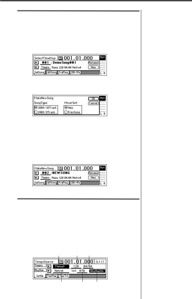
3. Create a new song
Before you can record a new composition, you must first create a new “song” on the D1600mkII.
1.Press the [SONG/CD] key. Then press the “SelSong” tab to access the [SONG/CD] “SelSong” tab page.
You can also access the “SelSong” tab page by pressing the [SONG/ CD] key several times.
2.Press the “New” button.
The “MakeNewSong” dialog box will appear.
3.Use “Song Type” to specify the bit depth and number of tracks for the song you want to create, and use “Mixer Set” to specify the mixer settings.
In this example, press the “Song Type” radio button “16Bit/16Track.” In the “Mixer Set” area, press the “New” radio button.
4.Press the “OK” button.
This creates a song named “NEWSONG.” If any songs exist already, the new song will be created following the existing songs.
4. Rhythm
Now let’s make rhythm settings so that you can listen to a rhythm pattern while you record.
Rhythm settings
1.Press the [TEMPO/RHYTHM] key. Then press the “Setup” tab to access the [TEMPO/RHYTHM] “Setup” tab page.
You can also access the “Setup” tab page by pressing the [TEMPO/ RHYTHM] key several times.
TempoSource Tempo Beat
SelRhythm Vol Rhythm
You can press the “Rename” button and input a name for the song. “2. Naming a song” (→p.35)
14
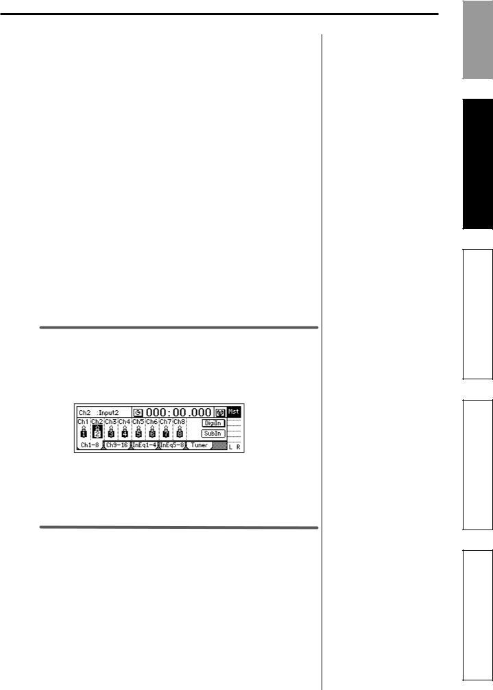
2.Press the “Rhythm” button to make the display read
“ ”.
”.
The [TEMPO/RHYTHM] key will light.
3.Raise the [MASTER] fader and verify that you hear the rhythm. Use the front panel [PHONES LEVEL] knob to adjust the volume of your headphones, or use the top panel [MONITOR OUT LEVEL] knob to adjust the volume of your monitor speakers.
Set the tempo, time signature, rhythm pattern, and rhythm volume
1.Select “TempoSource” and turn the [VALUE] dial to select the tempo source.
For this example, select “Manual.”
You can select the tempo source in the dialog box that appears when you press the “  ” button. Use the radio buttons to make your selection, and press the “OK” button.
2.Select “Tempo” and turn the [VALUE] dial to adjust the tempo.
3.Select “Beat” and turn the [VALUE] dial to specify the time signature.
4.Select “SelRhythm” and turn the [VALUE] dial to select the rhythm pattern you want to use.
You can select the rhythm pattern in the dialog box that appears when you press the “  ” button. Use the radio buttons to make your selection, and press the “OK” button.
5.Select “Vol” and turn the [VALUE] dial to adjust the volume of the rhythm.
5. Assign the input to a mixer channel
Assign the input to a mixer channel
1.Press the [INPUT/TUNER] key to access the [INPUT/TUNER] “Ch1–8” tab page.
2.Select the “Ch 8” icon, and turn the [VALUE] dial to select “INPUT 8.”
Since the front panel [GUITAR IN] jack is “INPUT 8,” the input from the [GUITAR IN] jack has been assigned to track channel 8.
6. Adjust the level
Adjust the level of the input signal while you watch the LCD screen.
[TRACK STATUS] key setting
Set the [TRACK STATUS] key to INPUT for the track you are using.
1.Press the front panel [TRACK STATUS] key of track 8 to select the INPUT setting (LED lit orange).
If you want the tempo, time signature, and/or rhythm pattern to change during the song, create a Tempo Map. (→p.72)
Quick Start
Step 1: Quick Recording
Step 2: Overdubbing
Step 3: Mixdown
Step 4: Mastering
15
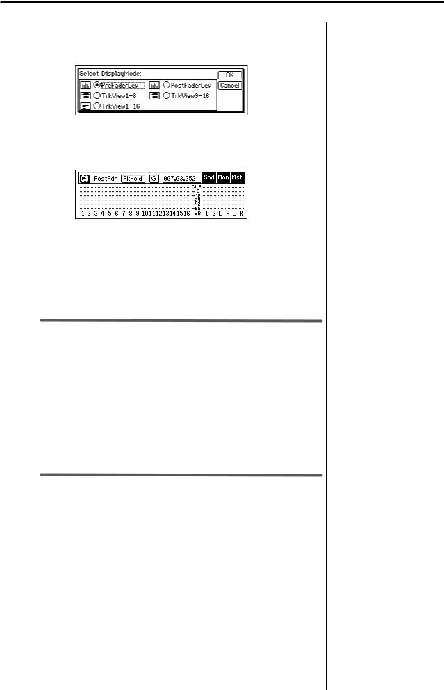
Pre-fader level display
2.Press the [METER/TRACK VIEW] key. From the screen that appears, press the “  ” button to open the dialog box.
3.From the Select DisplayMode dialog box, press the “PreFaderLev” radio button and press the “OK” button; the pre-fader screen will appear.
The ch.8 level meter will move when you play your guitar.
4.While watching the level meter, adjust the INPUT 8 [TRIM] knob so that the level meter goes as high as possible without reaching “CLP” when you play your guitar most loudly.
Use the [TRIM] knob to set the input level so that the peak indicator (the LED near the [TRIM] knob) lights when the volume is loudest.
7. Check the sound
Make settings so that you can hear the sound through your headphones or monitor speakers.
1.Raise the front panel [CHANNEL 8] fader to unity gain (0 dB).
2.Press the [SOLO/MONITOR] key to access the [SOLO/MONITOR] “Monitor” tab page.
3.Press the “MasterLR” button to select “ ”.
”.
4.While you play your guitar, gradually raise the [MASTER] fader. You will hear the sound of the guitar from your headphones or monitor speakers.
8. Record
Next you will record your guitar performance on track 8 while watching the status of the recording track on the track view screen.
Let’s start by recording a backing guitar part.
[TRACK STATUS] key setting
Specify the track on which you will record.
1.Press the front panel track 8 [TRACK STATUS] key to choose REC (LED lit red).
16
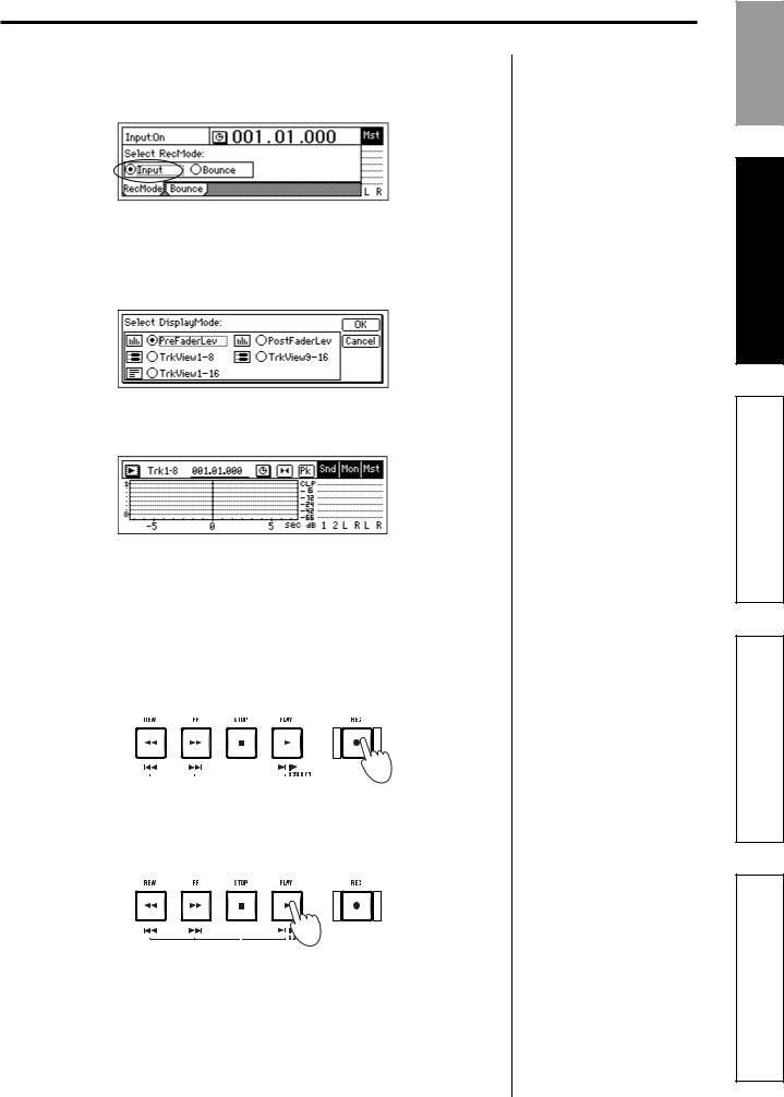
Check the record mode
2.Press the [RECORD] key to access the [RECORD] “RecMode” tab page. Verify that “Select RecMode” is set to “Input.”
Track View settings
3.Press the [METER/TRACK VIEW] key.
4.Press the “  ” button to open the “Select DisplayMode” dialog box.
5.Press the “TrkView1–16” radio button, and then press the “OK” button to display the track view screen.
Start recording
6.Make sure that the counter display is at the beginning of the song. At the beginning of the song, the counter value will be “001.01.000” or “000:00.000”.
7.Press the [REC] key.
The D1600mkII will be in record-ready mode, and the [REC] and [PLAY] LEDs will blink.
8.When you are ready to perform, press the [PLAY] key.
Recording will begin; begin performing on your instrument. During recording, the [REC] and [PLAY] LEDs will light.
In the track view screen, the bar will start moving at the point you press the [PLAY] key.
For details on the counter display and how to move to a different time, refer to “Changing the time location” (→p.46).
If you want to record the rhythm, refer to “3. Recording the rhythm” (→p.72).
If you want to use Trigger Recording, refer to “6. Other recording methods” (→p.43).
Quick Start
Step 1: Quick Recording
Step 2: Overdubbing
Step 3: Mixdown
Step 4: Mastering
17
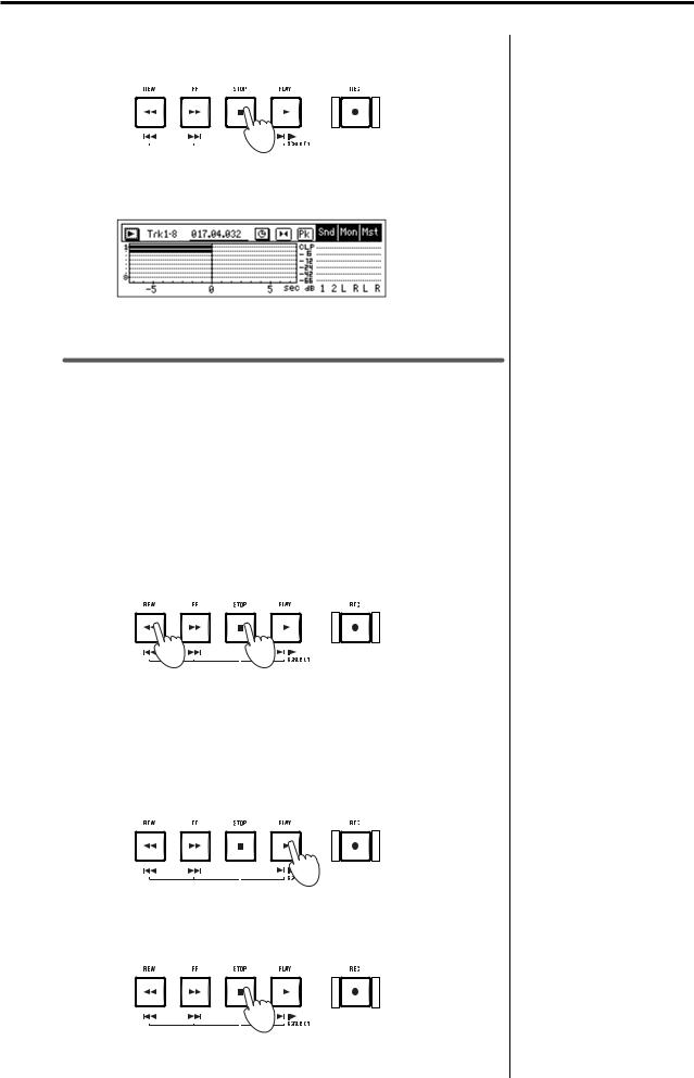
9.When you have finished performing, press the [STOP] key. Recording will stop, and the [REC] and [PLAY] LEDs will go dark.
In the track view screen, the region from the beginning to the end of your audio recording is displayed as a thick line.
Areas in which you did not perform are also displayed as a thick line.
9. Play back
Now we’ll play back the recorded song from the beginning.
[TRACK STATUS] key setting
Specify the track that you want to play back.
1.Press the front panel track 8 [TRACK STATUS] key to select PLAY (LED lit green).
Playback
2.Hold down the [STOP] key and press the [REW] key. The counter time will move to the beginning of the song.
3.Press the [PLAY] key.
Playback will begin, and the [PLAY] LED will light. Use the [MASTER] fader to adjust the volume.
You can use the front panel [PHONES] knob to adjust the volume of your headphones, or the top panel [MONITOR OUT LEVEL] knob to adjust the volume of your monitor speakers.
4.To stop playback, press the [STOP] key. The [PLAY] LED will go dark.
To stop the rhythm, access the [TEMPO/RHYTHM] “Setup” tab page and press the “Rhythm” button to turn it “Off.”
For details on the counter display and how to change the time location, refer to “Changing the time location” (→p.46).
18

Step 2: Overdubbing
“Overdubbing” is the process of recording additional performances on other tracks while you listen to the previously-recorded performance or rhythm.
For this example we’ll overdub an additional performance on guitar or keyboard while listening to the performance you recorded in Step 1.
We’ll also explain how to record your keyboard in stereo, and how to record on a virtual track. We will also apply an effect to your keyboard.
1. Record a guitar
While listening to the performance you recorded in Step 1, you can play a guitar phrases, riffs, or solos, and record them. In this example we’ll overdub on track 7.
Assign the input to a mixer channel
Assign the input of the guitar connected to INPUT 8 to mixer channel 7.
1.Press the [INPUT/TUNER] key to access the [INPUT/TUNER] “Ch 1–8” tab page.
2.Select the “Ch 7” icon and use the [VALUE] dial to select “INPUT 8.”
Check the level
When recording on more than one track, you don’t have to readjust the level each time if you are playing the same instrument in the same state; if so, proceed to the next step. Adjust the level only if you have switched sounds or instruments.
1.Press the track 7 [TRACK STATUS] key to select INPUT (LED lit orange).
2.In the [METER/TRACK VIEW] page, select “PreFaderLev.”
3.Turn the INPUT 8 [TRIM] knob while watching the level meter.
Check the sound
1.Set the [CHANNEL 7] fader to unity gain (0 dB).
2.In the [SOLO/MONITOR] “Monitor” tab page, make sure that the “MasterLR” button is “On.”
3.While playing your guitar, slowly raise the [MASTER] fader and check the sound in your headphones, etc.
[TRACK STATUS] key settings
You’ll need to select the appropriate status for the recording track, playback track, and other tracks.
1.Press the track 7 [TRACK STATUS] key to select REC (LED lit red).
2.Press the track 8 [TRACK STATUS] key to select PLAY (LED lit green).
3.Press the [TRACK STATUS] keys of the other tracks to select MUTE (LED dark).
Quick Start
Step 1: Quick Recording
Step 2: Overdubbing
Step 3: Mixdown
Step 4: Mastering
19
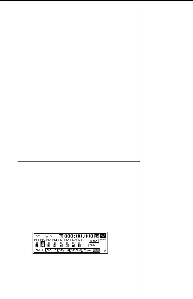
Check the recording mode
If you’ve already checked the recording mode, there’s no need to check it again; if so, proceed to the next step.
1.Access the [RECORD] “RecMode” tab page, and make sure that “Select RecMode” is set to “Input.”
Record
1.Set the recording-start location to the beginning of the song.
At the beginning of the song, the counter value will be “001.01.000” or “000:00.000”.
To move to the beginning of the song, press the counter value and turn the [VALUE] dial to the beginning of the song (“001.01.000” or “000:00.000”).
Alternatively, you can hold down the [STOP] key and press the [REW] key to move to the beginning of the song. However if you are already at the beginning of the song, holding down the [STOP] key and pressing the [REW] key will take you to the preceding song, so check the current location before you use this method.
2.Hold down the [REC] key and press the [PLAY] key to begin recording.
3.When you have finished recording, press the [STOP] key.
Play back
1.Hold down the [STOP] key and press the [REW] key to return to the beginning of the song.
2.Press the [TRACK STATUS] key to select PLAY for the track you just recorded.
3.Press the [PLAY] key to play back.
2. Record a keyboard
Here’s how to record a keyboard in stereo.
Connect your keyboard
1.Use the top panel [TRIM] knobs to set INPUT 5 and INPUT 6 to the minimum setting (+4 dB).
2.Lower the [MASTER] fader, and connect your keyboard to the [INPUT 5] and [INPUT 6] jacks.
Assign the inputs to mixer channels
1.Press the [INPUT/TUNER] key to access the [INPUT/TUNER] “Ch 1–8” tab page.
2.Select the “Ch 5” icon, and use the [VALUE] dial to select “INPUT 5.” In the same way, select the “Ch 6” icon and use the [VALUE] dial to select “INPUT 6.”
For details on the counter display and moving the time location, refer to “Changing the time location” (→p.46).
When using stereo input, you will be able to edit tracks and effects most efficiently if you select an odd-numbered and even-numbered pair of inputs (1–2, 3–4) and assign them to adjacent mixer channels.
20
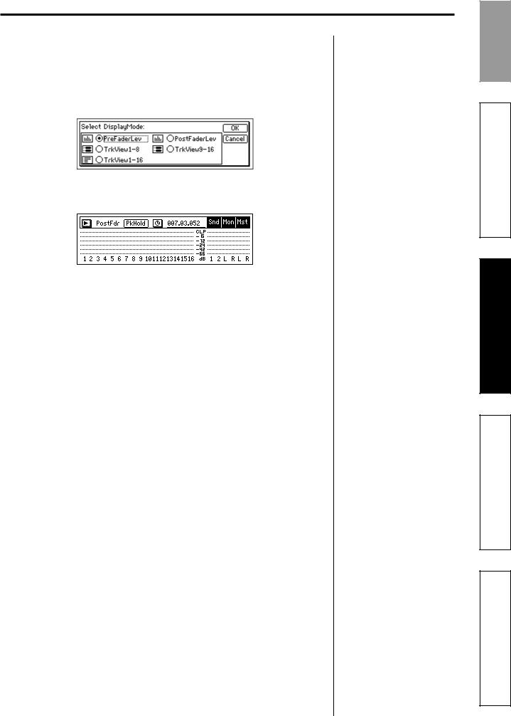
Check the level
Assign the audio from your keyboard to tracks, and check the levels.
1.Press the track 5 and 6 [TRACK STATUS] keys to select INPUT (LEDs lit orange).
2.Press the [METER/TRACK VIEW] key. In the screen that appears, press the “  ” button to open the dialog box.
3.In the Select DisplayMode dialog box, select the “PreFaderLev” radio button and press the “OK” button.
When you play your keyboard, the channel 5 and 6 level meters will move.
4.While watching the level meters, turn the INPUT 5 and 6 [TRIM] knobs so that the level is as high as possible without allowing the level meters to reach “CLP” when you play your keyboard most loudly.
Set the input level by turning the [TRIM] knob so that the peak indicator (the LED near the [TRIM] knob) lights when the volume is loudest.
Check the sound
1.Set the [CHANNEL 5, 6] faders to unity gain (0 dB).
2.In the [SOLO/MONITOR] “Monitor” tab page, make sure that the “MasterLR” button is “On.”
3.While playing your keyboard, slowly raise the [MASTER] fader. You will hear the sound through your headphones or monitor speakers.
Set the [TRACK STATUS] keys
Set the status of the recording tracks, playback tracks, and other tracks.
1.Press the track 5 and 6 [TRACK STATUS] keys to select REC (LED lit red).
2.Press the track 7 and 8 [TRACK STATUS] keys to select PLAY (LED lit green).
3.Press the [TRACK STATUS] keys of the remaining tracks to select MUTE (LED dark).
Make effect settings
Use the [INSERT EFFECT] “InsAsn,” “InsEff1,” and “InsEff2” tab pages to make insert effect settings. For details on the procedure, refer to “4. Make insert effect settings” (→p.24).
Quick Start
Step 1: Quick Recording
Step 2: Overdubbing
Step 3: Mixdown
Step 4: Mastering
21

Check the recording mode
If you have already checked the recording mode, there’s no need to check it again; if so, proceed to the next step.
1.Access the [RECORD] “RecMode” tab page, and make sure that “Select RecMode” is set to “Input.”
Record
1.Set the recording-start position to the beginning of the song.
At the beginning of the song, the counter value will be “001.01.000” or “000:00.000”.
2.Press the [REC] key, and then press the [PLAY] key to start recording.
3.When you have finished recording, press the [STOP] key.
Play back
1.Hold down the [STOP] key and press the [REW] key to return to the beginning of the song.
2.Press the [TRACK STATUS] key to set the recorded tracks to PLAY.
3.Press the [PLAY] key to play back.
3. Record vocals on virtual tracks
In this example, we’ll record several “takes” of vocals on the virtual tracks of track 4.
Connect a mic
1.Turn the top panel [TRIM] knob to set INPUT 4 to the minimum level (+4 dB).
2.Lower the [MASTER] fader, and then connect your mic to the [INPUT 4] jack. If you are using a condenser mic, you must connect it to the [INPUT 4] jack and then turn the phantom power switch on.
 Never turn on the phantom power switch before you connect the mic. If you connect or disconnect a mic with the phantom power turned on, you may damage your equipment.
Assign the input to a mixer channel
1.Press the [INPUT/TUNER] key to access the [INPUT/TUNER] “Ch 1–8” tab page.
2.Select the “Ch 4” icon, and use the [VALUE] dial to select “INPUT 4.”
Check the level
Assign the vocal signal to the track, and check the level.
1.Press the track 4 [TRACK STATUS] key to select INPUT (LED lit orange).
2.Press the [METER/TRACK VIEW] key. In the screen that appears, press the “  ” button to open the dialog box.
3.In the Select DisplayMode dialog box, select the “PreFaderLev” radio button, and then press the “OK” button.
4.Turn the INPUT 4 [TRIM] knob while you watch the level meter.
For details on the counter display and on how to change the time location, refer to “Changing the time location” (→p.46)
22
 Loading...